Table of Contents
Advertisement
Quick Links
We have 45,000 LP502030-PCM-NTC-LD-A02554 - EEMB - Lithium Battery Rectangular 3.7V 250mAh Rechargeable in
stock now. Starting at $0.034. This EEMB part is fully warrantied and traceable.
Looking for a discount?
Check out our current promotions!
This coversheet was created by Verical, a division of Arrow Electronics, Inc. ("Verical"). The attached document was created by the part supplier,
not Verical, and is provided strictly 'as is.' Verical, its subsidiaries, affiliates, employees, and agents make no representations or warranties
regarding the attached document and disclaim any liability for the consequences of relying on the information therein. All referenced brands,
product names, service names, and trademarks are the property of their respective owners.
00000005981LF-000
MDBT42Q-PATM
EOS Power
Raytac Corporation
Buy Now
Buy Now
Give us a call
1-855-837-4225
International: 1-555-555-5555
1-415-281-3866
1-415-281-3866
Arrow Electronics,
Arrow Electronics, Inc
Verical Division
9201 East Dry Creek Road
P.O. Box 740970
Centennial, CO 80112
Los Angeles, CA 90074-0970
Advertisement
Table of Contents

Summary of Contents for RAYTAC MDBT42Q-PATM
- Page 1 We have 45,000 LP502030-PCM-NTC-LD-A02554 - EEMB - Lithium Battery Rectangular 3.7V 250mAh Rechargeable in stock now. Starting at $0.034. This EEMB part is fully warrantied and traceable. 00000005981LF-000 MDBT42Q-PATM EOS Power Raytac Corporation Buy Now Buy Now Looking for a discount?
- Page 2 Version: A Issued Date: 2018/10/19 Approval Sheet (產品承認書) 產品名稱 (Product): BT 4.2 / BT 5 Module (nRF52832) 產品型號 (Model No.): MDBT42Q – ATM (Chip Antenna) MDBT42Q – PATM (PCB Antenna) Advantage of MDBT42Q & MDBT42Q-P series: 1. Long working distance: MDBT42Q: over 80 meters in open space.
-
Page 3: Table Of Contents
Index Overall Introduction ...................... 4 AT Command ......................... 4 2.1. List of supported commands ................. 4 2.2. AT Command Sets ....................5 2.3. Default Info ......................13 2.4. Pin Assignment ....................15 How to Control External MCU ..................17 3.1. How to Send AT Commands ................ - Page 4 11. Notes and Cautions ..................... 55 12. Basic Facts for nRF52 Chip ..................56 13. Useful Links ......................... 57 History of Firmware Revision .................... 58 Full List of Raytac’s BLE Modules ..................59 Release Note ........................61...
-
Page 5: Overall Introduction
1. Overall Introduction Raytac’s MDBT42Q-ATM & MDBT42Q-PATM is a BT 4.2 and BT 5 stack (Bluetooth low energy or BLE) module designed based on Nordic nRF52832 SoC solution, which incorporates: UART interface in only central/master role for data bridge in compact size (L) 16 x (W) 10 x (H) 2.2 mm. -
Page 6: At Command Sets
2.2. AT Command Sets 2.2.1. “Write” Commands Command Description Set scanned device name. Max. length of 20 characters AT+NAME e.g. AT+NAME123 (device name 123, 3 characters) AT+RESET Set to reset system AT+SCANOLDSTART Set to start scanning paired device AT+SCANNEWSTART Set to start scanning ALL devices AT+SCANSTOP Set to stop scanning AT+SLEEP... - Page 7 Command Description (25) AT+PHYMODE1MBPS Set PHY mode at 1Mbps (26) AT+PHYMODE2MBPS Set PHY mode at 2Mbps (27) AT+WAKEUPLOW Set logic low at wake-up when in deep sleep (28) AT+WAKEUPHIGH Set logic high at wake-up when in deep sleep Set idle time (Hex) e.g.
- Page 8 Command Description Set LED pattern for scanning paired device (Hex), where n = time when LED on, f = time when LED off e.g. 0x0064 (min. 100ms) (38) AT+SCANOLDPATTERNnnnnffff 0x1388 (Max. 5000ms) 0x00000000 (off) 0xFFFFFFFF (on) Set LED pattern for scanning all devise (Hex), where n = time when LED on, f = time when LED off e.g.
- Page 9 Command Description Set RX character UUID for NUS (Hex), (50) AT+RXCHARACTERUUIDuuuu e.g. 0x0002 Set service UUID for NUS (Hex), (51) AT+SERVICEUUIDuuuu e.g. 0x0001 Set base UUID for NUS (Hex), AT+BASEUUID e.g. 9ECADC240EE5A9E093F3A3B50000406E (52) uuuuuuuuuuuuuuuu & 14 byte is reserved for service / TX character uuuuuuuuuuuuuuuu RX character UUID, always be 0000.
- Page 10 2.2.2. “Read” Commands Command Description AT?NAME To retrieve scanned device name AT?VERSION To retrieve firmware version AT?MACADDR To retrieve IC MAC address AT?BAUDRATE To retrieve current UART baud rate AT?FLOWCONTROL To retrieve UART status of flow control AT?TXPOWER To retrieve RF TX power AT?XTAL To retrieve status of 32.768KHz oscillator AT?CONNECTINDICATOR...
- Page 11 Command Description (28) AT?TXCHARACTERUUID To retrieve TX character UUID value (Hex) (29) AT?RXCHARACTERUUID To retrieve RX character UUID value (Hex) (30) AT?SERVICEUUID To retrieve service UUID value (Hex) (31) AT?BASEUUID To retrieve base UUID value (Hex) (32) AT?ALLPARAMETERS To retrieve value of all parameters...
- Page 12 2.2.3. Response (Default) Response Command Description AT?NAME Raytac AT-UART (default) AT?VERSION e.g. version: 1.0 AT?MACADDR e.g. D352BDE1E414 0 baudrate9600 (default) AT?BAUDRATE (0 = 9600; 1 = 19200; 2 = 38400; 3 = 57600; 4 = 115200; 5 = 230400; 6 = 460800)
- Page 13 Command Response 00c80708 (default: Hex, 0.2sec on / 1.8sec off, (17) AT?CONNECTPATTERN nnnn: 0x00c8, ffff: 0x0708) 03e803e8 (default: Hex, 1sec on / 1sec off, (18) AT?SCANOLDPATTERN nnnn: 0x03e8, ffff: 0x03e8) 00640064 (default: Hex, 0.1sec on / 0.1sec off, (19) AT?SCANNEWPATTERN nnnn: 0x0064, ffff: 0x0064) Display “...
-
Page 14: Default Info
2.3. Default Info Description Default Raytac AT-UART Scanned device name 0x9E, 0xCA, 0xDC, 0x24, 0x0E, 0xE5, 0xA9, 0xE0, Base UUID 0x93, 0xF3, 0xA3, 0xB5, 0x00, 0x00, 0x40, 0x6E 0x0001 Service UUID TX characteristic: 0x0003; RX characteristic: 0x0002 Baud rate 9600bps,n,8,1... - Page 15 Description Default (23) Scanning new RSSI threshold -51 (Ascii). 0x01, 0x12, 0x23, 0x34, 0x45, 0x56, 0x67, 0x78, (24) Beacon UUID 0x89, 0x9A, 0xAB, 0xBC, 0xCD, 0xDE, 0xEF, 0xF0 (25) Company ID 0x004C...
-
Page 16: Pin Assignment
2.4. Pin Assignment Pin No. Name Pin Function Description Ground The pad must be connected to a solid ground plane No function Not connected No function Not connected No function Not connected No function Not connected No function Not connected No function Not connected No function... - Page 17 Pin No. Name Pin Function Description Output logic is selective about the action of wakeup from deep (22) Wakeup Input / Logic sleep Active-high with internal pull-high to disable hardware UART (23) UART PD Input interface. The default is disabled. (24) Ground The pad must be connected to a solid ground plane...
-
Page 18: How To Control External Mcu
3. How to Control External MCU 3.1. How to Send AT Commands ⚫ When BT is NOT connected (for all commands) Output low to P0.10 (UART PD pin) to enable UART interface. Please keep it enabling during the whole time when sending AT commands. Send any AT commands you want. -
Page 19: How To Return To Flashed Default Setting
3.2. How to Return to Flashed Default Setting * Only when BT is NOT connected * * Note that default baud rate is “9600bps,n,8,1”. For other default, please check “ 2.3 Default Info.” ⚫ Use Hardware Method Read P0.03 (indicator pin) first to check if BT is NOT in connection. Output a low pulse to P0.11 (flash default pin), then system will return to default setting. - Page 20 ⚫ Default Definition of LED (P0.4) Status Mode LED Status Idle 0.1 sec ON / 3.9 secs OFF Connected 0.2 sec ON / 1.8 secs OFF Scan the paired device 1 sec ON / 1 sec OFF Scan all devices 0.1 sec ON / 0.1 sec OFF...
-
Page 21: How To Start Scanning
3.3. How to Start Scanning This section describes how to start scanning using a physical button (hardware) or the AT Command (firmware) under various occasions. Before getting started, here are some notes applied to both methods. ⚫ Each central device is only able to pair with 1 Peripheral. ⚫... - Page 22 ⚫ Use Key/Button START Scanning Paired Device --- Press the button for less than 2 seconds and release it to start scanning paired device. START Scanning All Devices --- Press the button for 2 seconds or longer directly to start scanning all devices. STOP Scanning Paired / All Device(s) Press the button for less than 2 seconds and release it to stop scanning.
- Page 23 ⚫ Use AT Command START Scanning Paired Device --- Enter “AT+SCANOLDSTART” to start scanning paired device. START Scanning All Devices --- Enter “AT+SCANNEWSTART” to start scanning all devices. STOP Scanning Paired / All Device(s) Enter “AT+SCANSTOP” to stop scanning. The device will be back to idle and go into deep sleep after a given timeout.
-
Page 24: Report Of Data Transmission
4. Report of Data Transmission All testing is done under PHY mode at 1M bps D.L. means “Data Length” and D.I. means “Data Interval” in the table. 4.1. MCU → Peripheral (MDBT42Q-AT/MDBT42Q-PAT) → Central → Console Central Peripheral Baud Flow MCU D.L. - Page 25 4.2. MCU → Central → Peripheral (MDBT42Q-AT/MDBT42Q-PAT) → Console Central Peripheral Baud Flow MCU D.L. MCU D.I. Total D.L. Total Data Rate Connection Interval Connection Interval Rate Control (bytes) (ms) (bytes) Trans. Time (sec) (k-bytes/sec) 262152 min = 20ms min = 20ms 9600 999432 1,042...
-
Page 26: Product Dimension
5. Product Dimension 5.1. PCB Dimensions & Pin Indication ‧MDBT42Q-ATM PCB SIZE: (L) 16 x (W) 10 x (H) 2.2 mm... - Page 27 ‧MDBT42Q-PATM PCB SIZE: (L) 16 x (W) 10 x (H) 2.2 mm...
-
Page 28: Recommended Layout Of Solder Pad
5.2. Recommended Layout of Solder Pad Graphs are all in Top View, Unit in mm. -
Page 31: Rf Layout Suggestion (Aka Keep-Out Area)
“No-Ground-Pad” as wider as possible when there is no enough space in your design. Welcome to send us your layout in PDF for review at service@raytac.com or your contact at Raytac with title “Layout reviewing – MDBT42Q-ATM/MDBT42Q-PATM – YOUR company’s name”. -
Page 33: Footprint & Design Guide
Examples of “NOT RECOMMENDED” layout 5.4. Footprint & Design Guide Please visit “Support” page of our website to download. The package includes footprint, 2D/3D drawing, reflow graph and recommended spec for external 32.768khz. -
Page 34: Main Chip Solution
PCB/Printed Antenna - Unit Weight of Module: MDBT42Q-ATM: 0.64g / pc (±0.02g) ; MDBT42Q-PATM: 0.62g / pc (±0.02g) - Packaging Type: Anti-Static tray only - Minimum Package Quantity (MPQ): 88 pcs per Tray - Carton Contents: 1,760 pcs per carton (20 Full Tray + 1 Empty Tray) - Dimension of Carton: (L) 37 x (W) 21 x (H) 13 cm - Gross Weight: approx. -
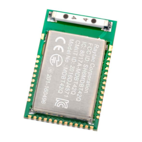
Page 35: Marking On Metal Shield
7.1. Marking on Metal Shield 7.2. Tray Info Anti-static tray is specifically designed for mass production. It can be used directly on SMT automatic machine. -
Page 36: Specification
8. Specification Any technical spec shall refer to Nordic’s official documents as final reference. Contents below are from “nRF52832 Product Specification v1.4”, visit the link to view full spec. 8.1. Absolute Maximum Ratings 8.2. Operation Conditions... -
Page 37: Electrical Specifications
8.3. Electrical Specifications 8.3.1. General Radio Characteristics 8.3.2. Radio Current Consumption (Transmitter) - Page 38 8.3.3. Radio Current Consumption (Receiver) 8.3.4. Transmitter Specification 8.3.5. Receiver Operation...
- Page 39 8.3.6. RX Selectivity...
- Page 40 8.3.7. RX Intermodulation 8.3.8. Radio Timing Parameters...
- Page 41 8.3.9. RSSI Specifications 8.3.10. CPU 8.3.11. Power Management...
-
Page 42: Reference Circuit
9. Reference Circuit Module is pre-programmed with Raytac’s AT command firmware. Default is NOT using “DC-DC mode” and is using internal 32.768khz RC oscillator. REMARK: ** When using DC-DC mode, please add L2 / L3 / C14. ** ** When... -
Page 43: Certification
10. Certification 10.1. Declaration ID... -
Page 45: Fcc Certificate (Usa)
10.2. FCC Certificate (USA) -
Page 46: Telec Certificate (Japan)
10.3. TELEC Certificate (Japan) -
Page 47: Ncc Certificate (Taiwan)
10.4. NCC Certificate (Taiwan) MDBT42Q Series... - Page 48 MDBT42Q-P Series...
-
Page 49: Ce Test Report (Eu)
10.5. CE Test Report (EU) -
Page 51: Ic Certificate (Canada)
10.6. IC Certificate (Canada) -
Page 52: Srrc Certificate (China)
10.7. SRRC Certificate (China) -
Page 53: Kc Certificate (South Korea)
10.8. KC Certificate (South Korea) -
Page 54: Rohs & Reach Report
10.9. RoHS & REACH Report Please visit “Support” page of our website to download. 10.10. End-Product Label It is suggested using following content adding to package or user manual or label to obey the regulation. Any rules of end-product label shall refer to each certification for final reference. 10.10.1. - Page 55 10.10.3. NCC (Taiwan) 請依下列標籤式樣自製標籤,標貼或印鑄於器材本體明顯處,始得販賣或公開陳列。 MDBT42Q Series MDBT42Q-P Series 平台廠商必須於平台上標示字樣「本產品內含射頻模組:ID 編號 CCAM16LP1180T2」或 「本產品內含射頻模組:ID 編號 CCAM16LP1181T1」 。 「平台」定義如下:若器材組裝本案模組,消費者仍能正常使用該器材主要功能,該器材得視 為平台。若器材不組裝本案模組,消費者不能正常使用該器材主要功能,該器材不能視為平 台。該類不同廠牌型號器材組裝本案審驗模組後,須分別申請型式認證。 10.10.4. IC (Canada) The IC statement should be included in the user manual when there is no enough space on label. Otherwise, it should be included on the label. “This device complies with Industry Canada license-exempt RSS Standard(s).
-
Page 56: Notes And Cautions
The module is not suitable for life support device or system and not allowed to be used in destructive device or system in any direct, or indirect ways. The customer is agreeing to indemnify Raytac for any losses when applying modules under such application as described above. -
Page 57: Basic Facts For Nrf52 Chip
Below is the comparison chart between nRF52840, nRF52832 and nRF52810. Any discrepancy shall refer to Nordic’s technical document as final reference. nRF52840 nRF52832 nRF52810 RAYTAC Click to see “Full List of Raytac’s BLE Modules” Model No.: Bluetooth 5 Long Range (x4) Bluetooth 5 High Speed... -
Page 58: Useful Links
Useful Links ⚫ Nordic Infocenter: https://infocenter.nordicsemi.com/index.jsp All the necessary technical files and software development kits of Nordic’s chip are on this website. Nordic Developer Zone: https://devzone.nordicsemi.com/questions/ ⚫ A highly recommended website for firmware developer. Interact with other developers and Nordic’s employees will help with your questions. The site also includes tutorials in detail to help you get started. -
Page 59: History Of Firmware Revision
History of Firmware Revision Compatible Release Description of Revision Note Ver. HW Build Date 2018/10/15 99-52832-12A release. -
Page 60: Full List Of Raytac's Ble Modules
Full List of Raytac’s BLE Modules MDBT40 & MDBT40-P Series Nordic Flash Series Raytac No. Antenna Solution Version Memory MDBT40-256V3 16 kb 256 K Chip MDBT40 nRF51822 Antenna MDBT40-256RV3 32 kb 256 K MDBT40-P256V3 16 kb 256 K MDBT40-P nRF51822... - Page 61 MDBT42Q Series (QFN Package IC) Nordic Flash Series Raytac No. Antenna Solution Version Memory nRF52832 MDBT42Q-512KV2 64 kb 512 K Chip MDBT42Q Antenna nRF52810 MDBT42Q-192K 24 kb 192 K nRF52832 MDBT42Q-P512KV2 64 kb 512 K MDBT42Q-P Antenna nRF52810 MDBT42Q-P192K 24 kb...
-
Page 62: Release Note
Release Note ⚫ 2018/10/19 Version A: 1 release...
Need help?
Do you have a question about the MDBT42Q-PATM and is the answer not in the manual?
Questions and answers