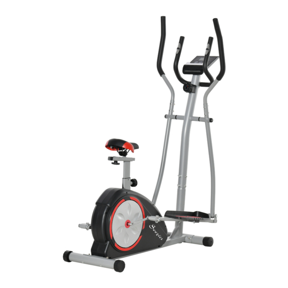

Summary of Contents for Soozier A90-256
- Page 1 INapa002_US A90-256 READ AND SAVAE THIS INSTRUCTION FOR FUTURE USE ASSEMBLY & INSTRUCTION MANUAL...
-
Page 2: Table Of Contents
CONTENTS SAFETY NOTICE EXERCISE SUGGESTION HARDWARE LIST PARTS LISTING EXPLODED DIAGRAM ASSEMBLY INSTRUCTIONS DIRECTIONS FOR USE... -
Page 3: Safety Notice
SAFETY NOTICE SAFETY: Always wear appropriate clothing and footwear such as training shoes when exercising. Please keep all children away from this item when in use. Please keep air circulation when exercising. Please put the pacakges and the bags on somewhere the children couldn'ttouch in case of some troubles. -
Page 4: Exercise Suggestion
EXERCISE SUGGESTION Warm-up:Please do warm-up fo 5-10 mins every time before you use this machine. Breathing:Please do not holding your breath when exercing. And stop it if you feel breath hardly. Load:Please exercise according to your body and increase it gradually. It is normal if you feel muscular soreness, and it would be better if you keep exercising. -
Page 5: Hardware List
HARDWARE LIST Bolt #31L Bolt for Left Pedal #31R Bolt for Right Pedal #32 Hex Bolt (M10*70MM) #34 Hex Bolt (M8*40MM) Connection Joint Connection Joint [2 pieces] [4 pieces] [1 piece] [1 piece] #35 Carriage Bolt(M8*75MM) #36 Carriage Bolt (M8*45MM) #37 Bolt (M8*35MM) #38 Bolt (M8*15MM) [4 pieces]... -
Page 6: Parts Listing
PARTS LISTING # Description # Description 1 Main Frame 33 Hex Bolt (M10x45 mm) 2A Front Stabilizer 34 Hex Bolt (M8x40 mm) 2B Rear Stabilizer 35 Carriage Bolt (M8x75 mm) 3 Center Post 36 Carriage Bolt (M8x45 mm) 4 Left Coupler Bar 37 Bolt (M8x35 mm) 5 Right Coupler Bar 38 M8×15Bolt (M8x15 mm) -
Page 7: Exploded Diagram
EXPLODED DIAGRAM Note: Some parts were completed before selling. 1:Please put all of the needed spare parts on the ground, and make ready for all of the hard wares before install the product. 2:Please put the product on the level ground, and install it as the instructions. -
Page 8: Assembly Instructions
ASSEMBLY INSTRUCTIONS Assembly step 1 A.) Front Stabilizer Assembly Please note, the Front Stabilizer(#02A) is the one with end caps that spin for ease of relocating the unit as referred to in illustration below.With the help of an assistant, attach the Front Stabilizer(#02A) to the front of Main Frame(#01)as illustrated below using two Carriage Bolts(#35),two Arc Washers (#47), two Spring Washers(#52), and two Nuts(#43). - Page 9 ASSEMBLY INSTRUCTIONS Assembly step 2 Remove the pre-assembled parts from Main Frame(#01) and set them aside nearby: SixBolts (#38),six Spring Washers(#52), and six Arc Washers(#47). With the help of an assistant, connect Monitor Wire(Middle)(#20) to Monitor Wire(Lower)(#19) as show in exploded diagram A, and Tension Controller(#17) to Tension Controller Cable(#18) as shown in exploded diagram B.Then, being careful to tuck the connected wires into the hollow tubing to avoid pinching/damaging the wires, slide Center Post(#03) onto the protruding tube of Main Frame...
- Page 10 ASSEMBLY INSTRUCTIONS Assembly step 3 Hardware Required Bolt A.) Coupler Bar Assembly The spindle assembly(28) to the vertical rod(03).on the right side, using one Special Washer(#53) followed by the Right Coupler Bar(#05),one D Shape Washer(#50), one #31L Bolt for Left Pedal End Cap(#54) and secure with one Bolt (#39).
- Page 11 ASSEMBLY INSTRUCTIONS Assembly step 4 A.) Handle Bar Assembly Insert the Right Handle Bar(#10) into the opening at the end of the Right Coupler Bar(#05)and secure it by inserting two Carriage Bolts(#36)and fastening with two Arc Washers(#47),two Spring Washers(#52)and two Nuts(#43). Repeat this process on the left side using Left Handle Bar(#09)and Left Coupler Bar(#04).
- Page 12 ASSEMBLY INSTRUCTIONS Assembly step 5 Pedal Assembly Place the Right Pedal(#14R) onto the Right Pedal Tube(#07) as shown and attach by inserting down two Hex Bolts(#34) secured by two Washers (#51)and two Nylon Nuts(#46). Repeat this process on the left side using Left Pedal(#14L) and the Left Pedal Tube (#06). Note: Distinguish between left and right sides, foot pedals respectively inscribed with "L"...
- Page 13 ASSEMBLY INSTRUCTIONS The method of use for the adjustable knob: Use the Adjustable Knob (17) can adjust the resistance.
-
Page 14: Directions For Use
DIRECTIONS FOR USE 1:Please put the product on the level ground, and lock all of the hardwares after you finished all of the steps. 2:Please adjust all of the adjustable parts to your confortable place. 3:Please do warm-up before you using this product.
Need help?
Do you have a question about the A90-256 and is the answer not in the manual?
Questions and answers