Table of Contents
Advertisement
Quick Links
R8HE / PPg3HE SERiES
inStAllAtion inStRUctionS
SinglE PAckAgE gAS HEAting / ElEctRic cooling
3-PhASE & SINgLE PhASE (REvISION A)
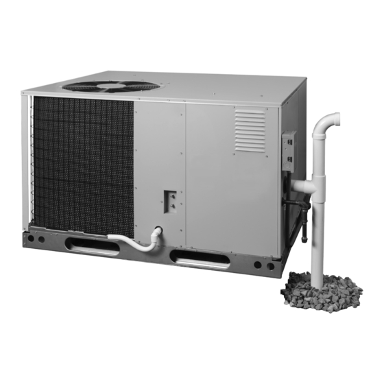
HoRiZontAl MoUnt SHoWn
FiRE oR EXPloSion HAZARD
• Failure to follow safety warnings exactly
could result in serious injury or property
damage.
• Installation and service must be performed
by a qualified installer, service agency or
the gas supplier.
• Do not store or use gasoline or other
flammable vapors and liquids in the vicinity
of this or any other appliance.
WHAt to Do iF YoU SMEll gAS
• Do not try to light any appliance.
• Do not touch any electrical switch; do not
use any phone in your building.
• Leave the building immediately.
• Immediately call your gas supplier from a
neighbors phone. Follow the gas suppliers
instructions.
• If you cannot reach your gas supplier, call
the fire department.
DO NOT DESTROY. PLEASE READ CAREFULLY & KEEP IN A SAFE PLACE FOR FUTURE REFERENCE.
WARning / AVERtiSSEMEnt
RiSQUE D'incEnDiE oU D' EXPloSion
• Le non-respect des avertissements de sécurité
pourrait entraîner des blessures graves, la mort
ou des dommages matériels.
• L'installation et l'entretien doivent être effectués
par un installateur qualifié, un organisme de
service ou le fournisseur de gazstaller, service
agency or the gas supplier.
• Ne pas entreposer ni utiliser de l'essence ni
d'autres vapeurs ou liquides inflammables dans le
voisinage de cet appareil,ni de tout autre appareil.
QUE FAiRE S'il Y A UnE oDEUR DE gAZ
• Ne pas tenter d'allumer aucun appareil.
• Ne toucher à aucun interrupteur électrique;
n'utiliser aucun téléphone dans le bâtiment.
• Évacuer l'immeuble immédiatement.
• Appeler immédiatement le fournisseur de gaz en
employant le téléphone d'un voisin. Respecter à
la lettre les instructions du fournisseur de gaz.
• Si personne ne répond, appeler le service des
incendies.
14 SEER / 95% AFUE
Advertisement
Table of Contents

Subscribe to Our Youtube Channel
Related Manuals for Nortek R8HE Series


Summary of Contents for Nortek R8HE Series
- Page 1 R8HE / PPg3HE SERiES 14 SEER / 95% AFUE inStAllAtion inStRUctionS SinglE PAckAgE gAS HEAting / ElEctRic cooling 3-PhASE & SINgLE PhASE (REvISION A) HoRiZontAl MoUnt SHoWn WARning / AVERtiSSEMEnt RiSQUE D’incEnDiE oU D’ EXPloSion FiRE oR EXPloSion HAZARD • Le non-respect des avertissements de sécurité •...
-
Page 2: Table Of Contents
tABlE oF contEntS coMPonEnt FUnctionS ..........23 iMPoRtAnt SAFEtY inFoRMAtion ......3 EQUiPMEnt MAintEnAncE..........24 REQUIREMENTS & CODES ..........4 Heat Exchanger & Burner Maintenance ........24 gEnERAl inFoRMAtion..........5 Cleaning of Burners ..............25 Before you install this unit ............5 REPlAcEMEnt PARtS............. -
Page 3: Important Safety Information
iMPoRtAnt SAFEtY inFoRMAtion WARning: Please read all instructions before servicing this equipment. Pay attention to all safety warnings and any other special PROPOSITION 65 WARNINg: This product notes highlighted in the manual. Safety markings are contains fiberglass insulation. Disturbing the used frequently throughout this manual to designate a insulation of this product during installation, degree or level of seriousness and should not be ignored. -
Page 4: Requirements & Codes
• The installer should become familiar with the units wiring nuisance shutdowns, and comfort or noise issues. diagram before making any electrical connections to the • Use only with the type of gas approved for this unit. Refer to the unit rating plate. unit. -
Page 5: General Information
gEnERAl inFoRMAtion Locating the Equipment • Select a solid, level position, preferably on a concrete This Single Package Gas Heating / Electric Cooling slab, slightly above the grade level, and parallel to the Unit is designed for outdoor rooftop or ground level home. -
Page 6: Vent Termination
• The vent termination must be located at least 3 feet WARning: above any forced air inlet located within 10 feet. • The vent termination must be located at least 4 feet Combustible air must not be drawn from a below, 4 feet horizontally from, or 1 foot above any contaminated atmosphere. -
Page 7: Circulating Air Supply
ciRcUlAting AiR SUPPlY • If a combination of indoor and outdoor air is used, the ducts and damper system must be designed so that the return air supply to the furnace is equal to the return air WARning: supply under normal, indoor return air applications. Products of combustion must not be allowed to Unconditioned Spaces enter the return air ductwork or the circulating air... -
Page 8: Clearances To Combustible Materials
Clearances to Combustible Materials ground Level These units are certified as combination heating and Ground level installations must be located according to cooling equipment for outdoor rooftop or ground level local building codes or ordinances and these requirements: installations. Units may be installed on combustible •... -
Page 9: Horizontal To Downflow Conversion
• Securement of the drain line to the inside surface of • All return air must pass through the filters before entering the roof curb is acceptable and should be made in the the evaporator coil. It is important that all filters be kept wood nailer area (top 3.5”) to avoid possible leaks or clean and replaced frequently to ensure proper operation penetrations to roofing materials. -
Page 10: Removing Filters From Internal Filter Rack
Removing Filters from Internal Filter Rack 3. Remove lower filter by lifting media to top of filter rack. Remove in the same manner as described in step 2. (If Equipped) 4. Install new filter in the filter rack as described in the 1. -
Page 11: Electrical Wiring
ElEctRicAl WiRing Pre-Electrical Checklist (Single & 3-Phase Models) WARning: √ Verify the voltage, frequency, and phase of the supply source match the specifications on the unit rating plate. √ Verify that the service provided by the utility is sufficient ELECTRICAL ShOCK, FIRE OR to handle the additional load imposed by this equipment. -
Page 12: Unbalanced 3-Phase Supply Voltage
Thermostat / Low voltage Connections • All 208-240 volt units are shipped from the factory wired for 240 volt transformer operation. For 208V operation, • This unit is designed to operate from a 24 VAC Class II remove the lead from the transformer terminal marked control circuit. -
Page 13: Heat Anticipator
heat Anticipator • For maximum dehumidification and energy efficiency, select an airflow near the middle or bottom of the CFM Verify if the thermostat being used for the installation range for that nominal capacity. has a heat anticipator setting. This function allows the •... -
Page 14: Dehumidification Options
air-flow. Verify the selected rise is within the specification cAUtion: shown on the furnace rating label or in the tables. Dehumidification Options To avoid personal injury or property damage, The fixed speed motor control board has a DEHUM make sure the motor leads do not come into connection that allows the system to increase the amount contact with any uninsulated metal components of humidity that is removed from the circulating air. -
Page 15: Gas Supply & Piping
gAS SUPPLY & PIPINg • All gas piping must be installed in compliance with local codes and utility regulations. In the absence WARning: of local codes the gas line installation must comply with the latest edition of the National Fuel gas Code ANSI z223.1 or CAN/CgA b149 Installation Codes. -
Page 16: High Altitude Conversion - Natural Gas
LP / Propane gas Conversion applied on each joint or union using a small paintbrush. If any bubbling is observed, the connection is not sealed adequately and must be retightened. Repeat the tightening WARning: and soap check process until bubbling ceases. •... - Page 17 -X24K060(X, XA) 10.0 60,000 57,000 39,000 37,050 30-60 0.80 24,000 11” x 8” -X30K060(X, XA) 10.0 60,000 57,000 39,000 37,050 30-60 0.80 29,000 11” x 8” -X36*080(X, XA) 10.0 80,000 76,000 52,000 49,400 35-65 0.80 36,000 11” x 8” -X42K080(X, XA) 10.0 80,000 76,000...
-
Page 18: Start Up & Adjustments
START UP & ADjUSTMENTS notE: When FAN ON is selected, the blower will operate at 50% of selected airflow when no call for heating or Pre-Start Check List cooling is present. √ Verify the unit is level and allows evaporator condensate Lighting the Appliance to drain. -
Page 19: Verifying System Heating
1. Turn ON the manual gas valve, located on the outside rise is the difference between the supply and return air of the unit to the ON position. temperatures. 2. Check all gas connections for leaks with a soap and notE: For typical duct systems, the temperature rise will water solution. -
Page 20: Measuring The Manifold Pressure
unit data label. To determine the firing rate, follow the Adjusting the Manifold Pressure steps below: notE: If adjustment must be made to either LOW or 1. Obtain the gas heating value (HHV) from the gas supplier. HIGH fire settings perform the following steps: 2. -
Page 21: Verifying Burner Operation
3. Set the thermostat above room temperature and verify cAUtion: the units operating sequence (page 21). notE: The over-temperature limit control should turn This unit uses R-410A refrigerant. DO NOT use off the gas valve within approximately four minutes any other refrigerant in this unit. Use of another (exact time depends on the efficiency of the close-off refrigerant will damage the unit. -
Page 22: Thaw Cycle Start Up / Shutdown
not close within 12 seconds, the control will display a 8. Blower Start-Up - After flame is proven, the furnace control energizes the circulating air blower after 22 Pressure Switch Open with Inducer On Fault. If the hall seconds. The blower will then ramp up to the airflow effect sensor switch does not close before 60 seconds selected for heating. -
Page 23: Blocked Vent / Condensate Disposal Shut Down
blocked vent / Condensate Disposal Shut For dehumidification, the DEHUM input on the FSHE board (Figure 11 (page 36)) can be used to control Down this function. If the DEHUM input is active and the unit The pressure switch is constantly monitored throughout is operating, the blower CFM is 75% of cooling for the the ignition cycle. -
Page 24: Equipment Maintenance
EQUiPMEnt MAintEnAncE local dealer about the availability of maintenance contracts. Routine maintenance should include the following: WARning: cAUtion: ELECTRICAL ShOCK, FIRE OR The unit should never be operated without a EXPloSion HAZARD filter in the return air system.Replace disposable Failure to follow safety warnings exactly could filters with the same type and size. -
Page 25: Cleaning Of Burners
Cleaning of burners tRoUBlESHooting If the burners must be cleaned, follow the steps below. Cooling Mode 1. Shut off the gas supply to the unit either at the meter If the unit does not operate in the cooling mode, check or at a manual valve in the supply piping. -
Page 26: Figures & Tables
FIgURES & TAbLES INSIDE PERIMETER 3/4" NPT OF BASE RAIL FEMALE DRAIN (IF USED) CONNECTOR 2.63 DOWNFLOW SUPPLY DUCT toP ViEW OPENING SinglE PHASE SHoWn 47.50 45.75 13.50 13.50 13.31 23.50 DOWNFLOW RETURN DUCT OPENING 1.75 HORIZONTAL HORIZONTAL RETURN DUCT SUPPLY DUCT OPENING OPENING... - Page 27 7.03 6.53 5.40 ELECTRIC SUPPLY 2.03 ENTRY (1.25” DIA.) LOW VOLTAGE ENTRY (0.875” DIA.) 3 TON, 3 PHASE SiDE ViEW MODEL ONLY BLOWER 3-PhASE MODELS ACCESS VENT ASSEMBLY (DOWNFLOW APPLICATION) 25.65 25.15 GAS SUPPLY ENTRY 14.82 (1.625” DIA) 2.03 47.50 5.40 2.03 ELECTRIC SUPPLY...
-
Page 28: Airflow Information
Airflow Information 2 & 2.5 TON 3.5 TON SWitcH SWitcH REcoMMEnDED REcoMMEnDED SEtting SEtting AIRFLOW (CFM) AIRFLOW (CFM) SWitcH SWitcH HigH HigH 5 6 7 8 5 6 7 8 SEtting SEtting HEAt HEAt HEAt HEAt 0 0 0 0 0 0 0 0 39,000 60,000... - Page 29 R8hE / PPg3hE -x24K060xA / -x30K060xA 60,000 bTUh, 30” CAbINET, 11”x8” bLOWER W- 3/4 hP ECM MOTOR 230 Volt oPERAtion SWitcH 0.20 0.30 0.40 0.50 0.60 0.70 0.80 0.90 1.00 SEttingS cFM RiSE cFM RiSE cFM RiSE cFM RiSE cFM RiSE cFM RiSE cFM RiSE cFM RiSE cFM RiSE 1039 1113 1073...
- Page 30 R8hE / PPg3hE -x36*080(x, xA) 80,000 bTUh, 30” CAbINET, 11”x8” bLOWER W- 1 hP ECM MOTOR 230 Volt oPERAtion SWitcH 0.20 0.30 0.40 0.50 0.60 0.70 0.80 0.90 1.00 SEttingS cFM RiSE cFM RiSE cFM RiSE cFM RiSE cFM RiSE cFM RiSE cFM RiSE cFM RiSE cFM RiSE 1272 1227 1181...
- Page 31 R8hE / PPg3hE -x42K080xA 80,000 bTUh, 34” CAbINET, 11”x10” bLOWER W- 1 hP ECM MOTOR 230 Volt oPERAtion SWitcH 0.20 0.30 0.40 0.50 0.60 0.70 0.80 0.90 1.00 SEttingS cFM RiSE cFM RiSE cFM RiSE cFM RiSE cFM RiSE cFM RiSE cFM RiSE cFM RiSE cFM RiSE 1347 1295 1242...
- Page 32 R8hE -x48*096(x, xA) & R8hE -x60*096(x, xA) 96,000 bTUh, 38”-42” CAbINET, 11”x10” bLOWER W- 1 hP ECM MOTOR 230 Volt oPERAtion SWitcH 0.20 0.30 0.40 0.50 0.60 0.70 0.80 0.90 1.00 SEttingS cFM RiSE cFM RiSE cFM RiSE cFM RiSE cFM RiSE cFM RiSE cFM RiSE cFM RiSE cFM RiSE 1347 1295 1242...
-
Page 33: Gas Information
gas Information CAPACITY OF bLACK IRON gAS PIPE (CU. FT. PER hOUR) FOR NATURAL gAS (SPECIFIC gRAvITY - 0.60) LENgTh OF PIPE RUN (FEET) noMinAl PiPE DIAMETER (IN.) 1 1/4 1,050 1 1/2 1,600 1,100 Input To Furnace (Btu/hr) Cubic Feet Per Hour Required = Heating Value of Gas (Btu/Cu. - Page 34 FOR YOUR SAFETY READ POUR VOTRE SÉCURITÉ. BEFORE OPERATING À LIRE AVANT L’EMPLOI ATTENTION! L’inobservation de ces instructions WARNING: If you do not follow these instructions peut entraîner un incendie ou une explosion pouvant exactly, a fi re or explosion may result causing property causer des dam mages à...
-
Page 35: Electrical Data
Electrical Data SinglE PHASE MoDElS MAXiMUM inDUcER VoltAgE MoDEl HEAting noMinAl BloWER MiniMUM coMPRESSoR OvER- MotoR RAngE nUMBER inPUt ElEctRicAl MotoR ciRcUit AMPS cURREnt R8HE / PPg3HE (bTUh) SUPPlY AMPS AMPAcitY MIN. MAx. PRotEction HIGH - 60,000 0.30 208/230-1-60 187 12.8 22.4 X24K060XA... -
Page 36: Electrical Diagrams
Electrical Diagrams THERMOSTAT TERMINAL STRIP Blower (Auto or Continuous ON) GREEN BLACK (Optional) 24VAC (Common) (Optional) For Economizer “OCC” Use Only Stage Heat WHITE 24VAC NOT USED NOT USED NOT USED YELLOW Stage Cool BROWN Stage Heat To Blower Control Board (Optional) DEHUM Figure 10. -
Page 37: Wiring Diagrams
Wiring Diagrams LINE- N LINE- N XMFR-N LINE LINE XMFR Figure 13. Single Phase, 2-5 Ton, 208/230v... - Page 38 LINE- N LINE- N XMFR-N LINE LINE XMFR Figure 14. Three Phase, 3-5 Ton, 208/230v...
- Page 39 LINE- N LINE- N XMFR-N LINE LINE XMFR Figure 15. Three Phase, 3-5 Ton, 460v...
-
Page 40: Charging Charts
Charging Charts 2 TON CHARGING CHART Remove refrigerant when above curve Add refrigerant when below curve Liquid Temperature (F) Figure 16. Charging Chart for 2 Ton Units 2.5 TON CHARGING CHART Remove refrigerant when above curve Add refrigerant when below curve Liquid Temperature (F) Figure 17. - Page 41 3 TON CHARGING CHART Remove refrigerant when above curve Add refrigerant when below curve 115 120 Liquid Temperature (F) Figure 18. Charging Chart for 3 Ton Units 3.5 TON CHARGING CHART Remove refrigerant when above curve Add refrigerant when below curve Liquid Temperature (F) Figure 19.
- Page 42 4 TON CHARGING CHART Remove refrigerant when above curve Add refrigerant when below curve Liquid Temperature (F) Figure 20. Charging Chart for 4 Ton Units 5 TON CHARGING CHART Remove refrigerant when above curve Add refrigerant when below curve 125 130 Liquid Temperature (F) Figure 21.
-
Page 43: Internal Filter Conversion
Internal Filter Conversion 1 Inch Filter Installations 2 Inch Filter Installations Figure 22. Filter Comversion... -
Page 44: Appendix A - Heat Exchanger Condensate Drain & Vent Kit (Horizontal Mount Applications)
APPENDIx A - hEAT ExChANgER CONDENSATE DRAIN & vENT KIT (hORIzONTAL MOUNT APPLICATIONS) vent Pipe & Drain hose Assembly WARning: 1. Connect the horizontal 13.25” x 2” PVC pipe (supplied with the unit) to the inducer motor rubber coupler ELECTRICAL ShOCK, FIRE OR and secure using 3”... -
Page 45: Preparing The Pit
Vertical Drain Pipe Installation notE to inStAllER 1. After the pit has been dug out, pour the rock or chat READ ThIS bEFORE YOU DIg! base to a level approximately 2” below the frost line. Mix in 50% of the limestone rock, chat, or lime pellets before you begin digging the pit for the condensate (if required by code) with the initial rock base. -
Page 46: Preparing The Trench
recommended for areas where temperatures are below 12. Prior to backfilling install the 4” flexible pipe filtration F for extended periods of time but is also dependent sleeve over the drain pipe or lay the permeable barrier on the final depth of the trench if the frost line cannot be material down over the length of pipe in the trench. - Page 47 JOINTS A & B CAN BE MECHANICALLY FASTENED USING STANDARD 1/2” LONG SCREWS. THIS WILL MAKE DISASSEMBLY EASIER FOR FUTURE CLEANING OR INSPECTION OF THE VENT AND DRAIN SYSTEM. JOINT B DRAIN HOSE & INSULATION OUTER 2” PVC PIPE 2” PAD (FIELD SUPPIED) GRADE LEVEL GRADE LEVEL...
-
Page 48: Appendix B - Heat Exchanger Condensate Drain & Vent Kit (Roof Curb Mount Applications)
APPENDIx b - hEAT ExChANgER CONDENSATE DRAIN & vENT KIT (ROOF CURb MOUNT APPLICATIONS) kit SUPPliED PARtS WARning: DEScRiPtion ELECTRICAL ShOCK, FIRE OR 2” pvC 22.5 d & 1/4” m eGree lbow Creen EXPloSion HAZARD prinG lamp 1/2” id 84” d Failure to follow safety warnings exactly could rain result in serious injury or property damage. -
Page 49: Setting The Unit
Setting the Unit C o m p l e t i n g t h e h e a t E x c h a n g e r Condensate Drain Installation iMPoRtAnt notE: before hoisting and setting the unit in place, the short iMPoRtAnt notE piece of factory installed drain line located next to Downflow applications require the factory set... - Page 50 ROOF MOUNTED UNIT (ROOF CURB AND ROOF NOT SHOWN) Condensate Drain Valve (”D” Position for Downflow Applications Only) 2” PVC x 22.5 Degree Elbow & 1/4” Mesh Screen Spring Hose Clamp Flexible Insulation (Optional) To building drain per J-Trap State and Local Codes Height 1/2”...
-
Page 52: Installation / Performance Check List
Is pipe free of restrictions? Filter(s) secured in place? Filter(s) clean? Single Phase Models Only Specifications & illustrations subject to change without notice or incurring obligations (05/15). O’Fallon, MO, © Nortek Global HVAC LLC 2015. All Rights Reserved. 709726B (Replaces 709726A)
Need help?
Do you have a question about the R8HE Series and is the answer not in the manual?
Questions and answers