
Summary of Contents for Braun Aquaboss (Eco) RO Dia II HT
- Page 1 Operating Instructions (Eco)RO Dia II Reverse osmosis system Rev. 6.4 dated 2022-02 Software Released Version: 1...
- Page 2 If you have problems with this system which you are unable to solve by consulting these operating instructions, please contact either B. Braun directly, your service technician or your authorized B. Braun partner with as precise a description as possible of the problems you are having and your unit details.
- Page 3 My suggestion: Use further pages if necessary. You can also enclose pages copied from the operating instructions with your suggestions entered on them. Please send your suggestion to: B. Braun Avitum AG Schwarzenberger Weg 73-79 34212 Melsungen Germany Fax: +49 (56 61) 75-0 Notes on the operating instructions Rev.
- Page 4 (Eco)RO Dia II Notes on the operating instructions The operating instructions contain information on the safe use of the system. Before a medical product can be used, users must be convinced of the functionality and proper state of the medical product according to applicable European and national requirements;...
-
Page 5: Signs And Symbols Used
(Eco)RO Dia II Signs and symbols used General This symbol is to be found on specific parts of the system and indicates that the valid CAUTION operating instructions must be observed. This symbol is to be found next to all the safety instructions where there is a risk of injury or health hazard. -
Page 6: Part 1 - Operating Instructions
(Eco)RO Dia II These operating instructions comprise two parts: Part 1 – Operating Instructions Here you will find subjects which are important for the normal operation of the system. 1. Safety 2. Field of application and intended use 3. (Eco)RO Dia II accessory list 4. -
Page 7: Table Of Contents
(Eco)RO Dia II Part 1 – Operating Instructions Notes on the operating instructions ..............4 Signs and symbols used ..................5 General ..........................5 Electrical symbols ......................5 Part 1 – Operating Instructions ..................6 Part 2 – Supplementary Operating Instructions ..............6 Safety .................. - Page 8 (Eco)RO Dia II Technical description............5-1 How it works ....................5-1 Design features ....................5-2 5.2.1 Aquaboss ® impulse return rinsing ..............5-2 ® 5.2.2 Aquaboss membrane module with no dead space ........5-3 5.2.3 Single pipe construction ................... 5-3 5.2.4 Minimum dead space piping in stainless steel ..........
- Page 9 (Eco)RO Dia II Commissioning / Decommissioning........8-1 System start-up ....................8-1 Interruption in production ................8-1 Machine start-up after shutdown due to a fault .......... 8-1 Putting the machine out of operation............8-2 Return and disposal..................8-2 Technical memo for PRESERVATION with sodium metabisulphite..8-3 Turning the equipment on ...........
- Page 10 (Eco)RO Dia II 13.9 Date_time, menu item 9 ................14-8 13.10 Type of system, menu item 10 ..............14-9 13.11 Operating hours meter, menu item 11............14-10 13.12 Hot RO, menu item 12 ................14-10 13.13 Service mode, menu item 13 ..............14-12 13.14 Fault history, menu item 15...............
-
Page 11: Safety
Keep these operating instructions within easy reach of the RO. • Commissioning, operation and maintenance may only be carried out by authorized, trained and B. Braun-instructed specialists. Electrical work may only be carried out by authorized, trained and instructed electricians. •... -
Page 12: Safety During Repair, Servicing And Maintenance
IMPORTANT Only original spare parts, accessories and consumables from B. Braun may be used → Part 2, chapter 9 and → Part 1, chapter 3. B. Braun does not accept any liability for damage caused by the use of other spare parts, accessories or consumables. -
Page 13: Residual Risks
(Eco)RO Dia II It is recommended that the permeate be tested for its microbiological quality at least every six months (see → Part 1, chapter 2 Bacteriology, pyrogenics). If the total germ count exceeds 30 CFU/ml, disinfection is recommended within 7 days (action limit). ... -
Page 14: Contraindications And Potential Undesirable Side Effects
(Eco)RO Dia II Contraindications and potential undesirable side effects 1.6.1 Contraindications Do not use the reverse osmosis system if the chemical or microbiological quality of the raw water is not clear. Do not use the reverse osmosis system if the raw water does not satisfy the requirements of guideline 98/83. -
Page 15: Area Of Application And Intended Use
IMPORTANT The quality of the feed water upstream of the water softener (ion exchanger) must comply with the requirements of EC guideline 98/83/EC of the Council dated November 3, 1998, concerning the quality of water for human usage. For B. Braun-specific deviations from or supplements to the guideline see → Part 2, chapter 7... -
Page 16: Functional Features
(Eco)RO Dia II Functional features • Unauthorized operating states that could endanger the connected medical products or even the patients are prevented by measuring equipment and related control measures (alarm and error functions). • Emergency operation with soft water is possible (following doctor's approval) •... -
Page 17: Water Quality Requirements
(Eco)RO Dia II Water quality requirements In order not to endanger patients' health, the water qualities must meet certain guidelines, depending on their use: Definition/ Drinking water Feed water for reverse Dialysis water / permeate / water for diluting Water quality (water for osmosis Aquaboss concentrated haemodialysis solutions... -
Page 18: Contraindications And Side Effects
(Eco)RO Dia II Definition/ Drinking water Feed water for reverse Dialysis water / permeate / water for diluting Water quality (water for osmosis Aquaboss concentrated haemodialysis solutions human use) (Eco)RO Dia Directive 98/83/EC 98/83/EC + process ISO 13959: European Recommendation limit values 2009 Pharmacopoeia... -
Page 19: Eco)Ro Dia Ii Accessory List
(Eco)RO Dia II (Eco)RO Dia II accessory list Pos. Item no.: Name Description: 3037754 Sterile filter 20”, 0.2 µm, Sterile hot polysulphone membrane filter, pre-rinsed with ultra- absolute pure water: ® In conjunction with an Aquaboss dialysis water treatment system, the Aquaboss ®... - Page 20 (Eco)RO Dia II Pos. Item no.: Name Description: 2100100 Kit for impulse shear force Kit for equipping Aquaboss ® EcoRO Dia systems for the rinsing impulse-based increase in flow speeds in the primary and secondary ring pipes to prevent the formation of biofilms, comprising: •...
-
Page 21: Use In Combination With Other Equipment
The (Eco)RO Dia II and further medical products can be put into circulation independently of one another. No combination of medical products will be put into circulation by the manufacturer as a standard variation. The manufacturer, B. Braun Avitum AG, stipulates the following reverse osmosis system requirements for combination with other equipment: •... - Page 22 (Eco)RO Dia II Part 1 • Page 4-2 Use in combination with other equipment Rev. 6.4 dated 2022-02 Software Released Version: 1 Part 1 – Operating Instructions...
-
Page 23: Technical Description
(Eco)RO Dia II Technical description The Aquaboss ® (Eco)RO Dia II provides the operator with a consumption-controlled reverse osmosis system. A 4-line LCD plain text display allows all operating parameters to be called up and monitored at any time. A special rinsing and disinfection program developed for compact systems with the integrated Aquaboss ®... -
Page 24: Design Features
(Eco)RO Dia II Design features ® 5.2.1 Aquaboss impulse return rinsing During normal operation of the reverse osmosis system, deposits can accumulate on the membrane (see → Fig. 5-1 “Permeate mode”) depending on the quality of the supply water. Depending on their origin, these can cause long-term damage to the membrane, thus reducing permeate quality. -
Page 25: Aquaboss ® Membrane Module With No Dead Space
(Eco)RO Dia II 5.2.2 Aquaboss ® membrane module with no dead space Raw water (RW) Permeate Concentrate Figure 5-3: Membrane module with no dead space Thanks to the new design of the membrane module (patented), it is guaranteed that the dead space between the outside of the membrane and the inside of the pressure pipe is continually flushed. - Page 26 (Eco)RO Dia II Part 1 • Page 5-4 Technical description Rev. 6.4 dated 2022-02 Software Released Version: 1 Part 1 – Operating Instructions...
-
Page 27: Functions
(Eco)RO Dia II Functions Process diagram 6.1.1 RO Dia II Key for RO Dia II PI 1-6: Manometer Shut off valve for emergency PISAL1: Pressure sensor level regulation storage tank operating mode Pre-filter PSAH1: Pressure switch for excessive ring piping Shut off valve for emergency Sterile filter pressure... -
Page 28: Ecoro Dia Ii
(Eco)RO Dia II 6.1.2 EcoRO Dia II Key for EcoRo Dia II NV3: Throttle valve RO II concentrate PH2: Sampling cock for ring piping Pre-filter NV4: Throttle valve RO I concentrate return flow Sterile filter PH3: Sampling cock for soft water TISHAH1: Feed temperature Pump 1 Shut off valve for emergency... -
Page 29: Functions
(Eco)RO Dia II Functions Technical overview: see → Part 2, chapter 7 “Operating modes”. NOTE 6.2.1 Water supply Soft water is made available through a softening plant with the appropriate capacity. To protect the reverse osmosis system, any mechanical contamination still present is removed by means of a filter element (VF). -
Page 30: Dual-Stage Reverse Osmosis System (Eco)Ro Dia Ii
(Eco)RO Dia II The permeate enters the ring piping, which can be blocked by ball cock K6, via a hose bridge. The water flows through the surge tank DG which has no dead space and is routed to the individual tapping points. The end of the ring piping can be blocked off using ball cock K7. -
Page 31: Ring Piping Pressure
→ Part 1, chapter 6, paragraph 6.2.7 “System production pressure”. B. Braun prescribes a weekly check of the Hydrowatch on the installed membrane surge tank (DG). If the red indicator is visible in the viewing glass, please contact your B. Braun Avitum AG service technician immediately. -
Page 32: Standby Mode
(Eco)RO Dia II 6.2.12 Standby mode Standby mode is used to prevent the development of biofilms/contamination by interrupting standstill times in periods in which no permeate is required. The system is switched on automatically at the set times to flush out the ring piping and the modules. For this, the operating mode selection switch is turned to position 2. -
Page 33: Description Of Components
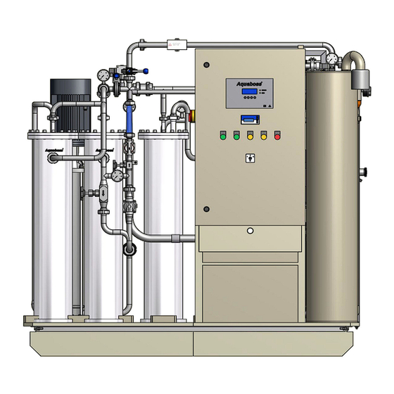
(Eco)RO Dia II Description of components Pipeline / Switch cabinet Figure 7-1: Aquaboss ® (Eco)RO Dia II Front view 1. Main switch 2. Operating mode selection switch (position 1,0,2) 3. Display – 4 lines with 20 characters each 4. Display-guided key control 5. -
Page 34: Signal Lamps
The control unit has failed. The system continues to product the full amount, however, since the power supply has not failed. In this switching state, rinsing no longer occurs. Please contact the B. Braun service department. • “Alarm” lamp lights up As soon as the fault lamp lights up, the type of fault appears on the display. -
Page 35: Display And Keypad
(the values relevant for operation can only be changed by persons authorised to do so by the manufacturer). B. Braun advises proceeding with the help of the operating instructions when using the system for the first time and when operators are not familiar with the system. -
Page 36: Conductivity Display
(Eco)RO Dia II 7.3.2 Conductivity display The conductivity display (→ Part 1, chapter 7, paragraph 7.1 “Pipeline / Switch cabinet”, pos. 7) is used to monitor the permeate quality. It shows the current conductivity of the produced permeate in the ring piping intake. - Page 37 (Eco)RO Dia II To return to measuring mode (MEASURING): NOTE → Press <EXIT> or wait for “timeout”. Further information about the program and details of electrical connections and calibration NOTE are provided in a separate instruction manual: JUMO dTRANS CR 02 “Transmitter/controller for conductivity, TDS, resistance, temperature and standard signals”...
- Page 38 (Eco)RO Dia II Part 1 • Page 7-6 Description of components Rev. 6.4 dated 2022-02 Software Released Version: 1 Part 1 – Operating Instructions...
-
Page 39: Commissioning / Decommissioning
Commissioning, operation and maintenance may only be carried out by authorized, trained and B. Braun-instructed specialists. Electrical work is to be carried out only after completely disconnecting the system from the power supply and only by authorized, trained and instructed electricians. -
Page 40: Putting The Machine Out Of Operation
Battery (1 pc. / item no. 40410) Figure 8-1: Removing the battery In accordance with legislative regulations, B. Braun Avitum AG offers to take back systems it supplies and dispose of these as stipulated by legislation. Part 1 • Page 8-2 Commissioning / Decommissioning Rev. -
Page 41: Technical Memo For Preservation With Sodium Metabisulphite
(Eco)RO Dia II Technical memo for PRESERVATION with sodium metabisulphite Protection against contamination and stabilisation of reverse osmosis membranes • Before preservation, rinse the membranes with good-quality water free of chlorine (dissolved solid matter < 5.0 g/l). Use 120 litres of water for each 8-inch membrane. Table 8-1: Filling volumes of preservative / antifreeze Number of... - Page 42 (Eco)RO Dia II During preservation, the system must be clearly marked with the following information: NOTE • Type of preservative • Date of preservation • Contact to responsible doctor and operating personnel. After preservation, disinfection must be carried out according to → Part 1, chapter 12 before NOTE normal start-up.
-
Page 43: Turning The Equipment On
(Eco)RO Dia II Turning the equipment on Operating status and phase dd.mm.yy hh:mm EcoRO Dia II CPU test Menu To supply the system with power, insert the mains plug and turn the main switch to ON. Switch the operating mode switch to 0 = System off. dd.mm.yy hh:mm System off... - Page 44 (Eco)RO Dia II Part 1 • Page 9-2 Turning the equipment on Rev. 6.4 dated 2022-02 Software Released Version: 1 Part 1 – Operating Instructions...
-
Page 45: Dialysis Mode
(Eco)RO Dia II 10. Dialysis mode Dialysis mode supplies the connected dialysis machines. (Among other things, the dialysis machine dilutes haemodialysis concentrate to provide ready-to-use dialysate.) Disinfection is not permitted during dialysis. NOTE Dialysis mode dd.mm.yy hh:mm Dialysis mode Dialysis mode begins when the operating mode switch is switched to 1 = System ON. - Page 46 (Eco)RO Dia II Part 1 • Page 10-2 Dialysis mode Rev. 6.4 dated 2022-02 Software Released Version: 1 Part 1 – Operating Instructions...
-
Page 47: Standby Mode
(Eco)RO Dia II 11. Standby mode Standby mode is started by switching the operating mode selection switch to position 2 or, if it is already on 2, by using a remote control or the auto on/off function to switch the system to standby mode. Dialysis is not possible during “standby mode”. - Page 48 (Eco)RO Dia II Part 1 • Page 11-2 Standby mode Rev. 6.4 dated 2022-02 Software Released Version: 1 Part 1 – Operating Instructions...
-
Page 49: Disinfection / Cleaning
30 CFU/ml). IMPORTANT After the RO has been at a standstill for > 72 hours, carrying out disinfection is recommended. A B. Braun reverse osmosis system may only be disinfected or cleaned by B. Braun- CAUTION authorized and trained personnel. -
Page 50: Disinfection
In this respect, a basic solution is used in the supply tank, where the concentration of the disinfectant must not exceed 8% (otherwise the membrane would be damaged!). Consult B. Braun in the case of proven contamination by fungi/yeast or spores. - Page 51 15 minutes. The reaction time of the disinfectant in its diluted form on membranes must not exceed 30 minutes and must be completed directly by a rinsing process. IMPORTANT Only use disinfectants approved by B. Braun. Table 12-1:...
- Page 52 (Eco)RO Dia II After disinfection (DI), the dialysis personnel must check that there is no disinfectant in the CAUTION system at each dialysis station before commencing dialysis. A softener may only be used with a pipe disconnector of the type EA1 or with a free intake. CAUTION The system must be disconnected completely from the mains supply line before disinfection of the softener.
- Page 53 (Eco)RO Dia II Reaction time Disinfection (DI) Following recirculation mode, the system automatically switches to Reaction time Time left ### min reaction time. << Continue Disinfection (DI) Open valve PH2 When the reaction time has elapsed, the display calls for sampling cock PH2 to be opened and the system to be switched to flushing operation ...
-
Page 54: Cleaning
(Eco)RO Dia II 12.3 Cleaning 12.3.1 Technical information sheet for CLEANING the Aquaboss®-reverse osmosis systems Citric acid cleaning of 8” modules to remove metal hydroxides and calcium carbonate. • Prior to the cleaning process: Rinse the system with permeate. 120 litres of permeate are required for the complete rinsing of an 8”... - Page 55 (Eco)RO Dia II Filling the cleaning solution Cleaning After the cleaning solution has been filled into the supply tank, the next Fill in cleaner program step is initiated by pressing the “->” key. -> << Recirculation mode Cleaning Recirculation mode In recirculation mode, the cleaning solution is guided through all the pipe Time left ### min...
- Page 56 (Eco)RO Dia II Part 1 • Page 12-8 Disinfection / Cleaning Rev. 6.4 dated 2022-02 Software Released Version: 1 Part 1 – Operating Instructions...
-
Page 57: Menu Selection
(Eco)RO Dia II 13. Menu selection When >Menu< is selected, the key data shown are listed. 1 Specifications 2 Prm dialysis mode Certain program items have a separate method for display and input. 3 Auto on/off This is shown by selecting the respective menu sub-item as follows: 4 Prm standby mode 5 DI data A) Display and... -
Page 58: Parameters For Dialysis Mode, Menu Item 2
(Eco)RO Dia II Flow rate: Volume flows FISCAL 1 permeate feed in ring piping [l/h] FISCAL 2 permeate return [l/h] FISCAL 3 concentrate in channel [l/h] Yield: WCF (water conversion factor = water yield of permeate per water feed) [%] Consumption [l/h] Concentrate [l/h] Ov. - Page 59 (Eco)RO Dia II Parameter Function Area Factory setting Interval RO II: Time interval for impulse rinsing of RO II 0 … 180 min 60 min Pressure build-up RO II: Duration of pressure build-up 0 … 15 sec 5 sec Flush time RO II: Duration of flush 0 …...
-
Page 60: Auto On_Off, Menu Item 3
(Eco)RO Dia II Parameter Function Area Factory setting Maintenance interval: Time interval for the reminder to carry out system maintenance 6, 12, 24 months 12 months Change prefilter: Time interval for the reminder to change the prefilter 0 … 8 weeks 8 weeks MB samples: Time interval for the reminder to carry out microbiological sampling... -
Page 61: Parameters For Standby Mode, Menu Item 4
(Eco)RO Dia II 13.4 Parameters for standby mode, menu item 4 (Requires main switch to be in position 2) The process data for standby mode can be viewed or changed in the Standby interval sub-menu standby mode parameters. Duration standby Temp. -
Page 62: Disinfection Data, Menu Item 5
(Eco)RO Dia II Parameter Function Area Factory setting Operating time ISS Duration of impulse shear force rinsing (ISS) 0 … 300 sec 300 sec Reaction time MVY30 Reaction time of the solenoid valve Y30 for opening 0 … 30 sec open: 3 sec and closing closed: 5 sec... -
Page 63: Cleaning Data, Menu Item 6
(Eco)RO Dia II 13.6 Cleaning data, menu item 6 (Requires main switch to be in position 2) The parameters for the menu-guided control of cleaning are specified in Recirculation time the sub-menu cleaning data. Reaction time Switch on pump M3? R cancel? Factory settings? ... -
Page 64: Passwords, Menu Item 8
(Eco)RO Dia II Parameter Function Area Factory setting End of monitoring End of leakage monitoring: auto start after x min 0 ... 60 min 0 min Silicate factor Selection of silicate factor of the feed water 0/1/2/3 0 = off 1 = silicate <... -
Page 65: Type Of System, Menu Item 10
(Eco)RO Dia II 13.10 Type of system, menu item 10 Depending on the pipes and electronic components fitted, this is a 10 Choose system A) Display B) Entry << ENTER EcoRO Dia I: single-stage reverse osmosis system with impulse rinsing for improving membrane System type functionality... -
Page 66: Operating Hours Meter, Menu Item 11
(Eco)RO Dia II 13.11 Operating hours meter, menu item 11 The most important operating hours (depending on the type set) can be Op. hours meter viewed in the operating hours meter menu item. Pump M1 ######## h Pump M2 ######## h Pump M1 Upstream of 1 osmosis membrane stage... - Page 67 (Eco)RO Dia II Digital inputs Function (“1”, if ...) Pump M3 Pump OK Reserve Temperature OK Temperature sensor is working, measurement within the permitted range Cond. perm. OK Conductivity measurement is working, value within the permitted range LSHAL1 Lower level switch, tank LSHL2 Upper level switch, tank PSAH1...
-
Page 68: Fault History, Menu Item 15
(Eco)RO Dia II Digital outputs Function MV Y30 Impulse shear force rinsing MV Y5.1.1 Ring piping return LED Y5.1.1 Visual display of Y5.1.1 on blind circuit diagram HotRinse Eco Disinfection Alarm bridge of the conductivity device during disinfection, cleaning or hot cleaning Release HR Release for external hot cleaning system Rel. -
Page 69: Faults / Causes / Correction
(if several exist) can be queried using the arrow keys B. Braun recommends connecting the alarm output (fault message) and warning information NOTE output (disinfection operation) to a central alarm. This can be the B. Braun remote control system, for example. Faults / Causes / Correction Part 1 •... -
Page 70: Causes Of Faults And Their Correction
(Eco)RO Dia II 14.2 Causes of faults and their correction 14.2.1 Fault code Alarm / Error Cause / Condition Operating phase initiated (Eco)RO Dia II Internal RAM and CPU test System off dd.mm.yy hh:mm Error 01 Menu Display of internal watchdog → System off dd.mm.yy hh:mm... - Page 71 (Eco)RO Dia II Alarm / Error Cause / Condition Operating phase initiated Conductivity alarm value 5 sec System continues to run, discharge dd.mm.yy hh:mm Alarm 09 achieved according to 14.2 dialysis mode pa- Cond. too high Specification menu 2.18 rameters, menu “Open Y9 when fault” Menu Conductivity greater than limit 5 sec...
- Page 72 (Eco)RO Dia II Alarm / Error Cause / Condition Operating phase initiated The level has dropped below System off dd.mm.yy hh:mm Error 17 LSHAL1 during standby mode Leakage alarm break or intermediate rinsing, or a difference FISCAL 1 => FISCAL2 is determined during intermediate rinsing.
- Page 73 (Eco)RO Dia II Alarm / Error Cause / Condition Operating phase initiated Automatic fuse has failed Yes System off dd.mm.yy hh:mm Error 25 Permit in dialysis mode using the Control volt. ROII RO I emergency mode key If Y9 is not triggered despite 5 sec Yes System continues to run dd.mm.yy...
-
Page 74: Other Faults
(Eco)RO Dia II 14.2.2 Other faults Fault Cause Effect / Correction Supply tank empty • Water supply • Check on water supply and pre-treatment • Y 10 Pump is making noises • Level in supply tank too low • Switch off pump •... -
Page 75: Emergency Operating Modes
“Emergency mode I/II” water transport continues using one RO stage. Heed the warning notes. In case replacement operation mode has to be activated, the B. Braun Service department has to be contacted. Emergency mode is only permitted if the physician responsible agrees! CAUTION 15.1... - Page 76 90° upwards. 4. Switch on the hard water monitor by hand (if available) During soft water emergency operation, B. Braun recommends closing the flap on the loop return to avoid premature depletion of the softener.
-
Page 77: Emergency Operation When The Control System Fails
(Eco)RO Dia II 15.3 Emergency operation when the control system fails If the control system fails, the system automatically switches to emergency mode. All pumps and solenoid valves on. Y10 is controlled via LSAL2. Conductivity and pressure monitoring are enabled. 15.4 Detailed view of the emergency operation valve flaps (using the example of a 2-step system) - Page 78 (Eco)RO Dia II Valve Y5.1 Valve Y5 Flap K1 Manual operation of the solenoid valve (only dur- ing emergency opera- tion with soft water) Figure 15-2: Emergency operation fittings K1/Y5.1 In emergency operation via RO I, the valve Y5.1 is opened through the control system (→ Part 1, chapter 15, paragraph 15.1 “Production of permeate in emergency mode”).
- Page 79 (Eco)RO Dia II Part 2 – Supplementary Operating Instructions Handover declaration for the operating instructions..1-1 ® Aquaboss reverse osmosis system ............1-1 Customer’s address..................1-1 Confirmation of handover of operating instructions ........1-1 System handover date ................... 1-2 Maintenance and servicing personnel ............1-2 The system was handed over to the customer by ........
- Page 80 (Eco)RO Dia II Commissioning log .............. 5-1 System parameters ..................5-1 Commissioning log ..................5-2 System key data..............6-1 Manufacturer’s address................. 6-1 Copyright ......................6-1 Type plate ....................... 6-1 Technical data..............7-1 Specifications ....................7-1 7.1.1 (Eco)RO Dia II ....................7-4 Design data .....................
- Page 81 (Eco)RO Dia II 7.13 Overview of operating phases ..............7-11 7.13.1 Valve designation ................... 7-11 7.13.2 Operating modes.................... 7-12 7.14 EMC guidelines..................... 7-14 Maintenance and operating logs......... 8-1 Specific checks for your system ..............8-2 Medical product log and maintenance / technical safety check log ..8-3 Medical product log (Eco)RO Dia II ..............
- Page 82 (Eco)RO Dia II Section 2 • Page 4 Contents Rev. 6.4 dated 2022-02 Software Released Version: 1 Section 2 – Operating Instructions...
-
Page 83: Handover Declaration For The Operating Instructions
(Eco)RO Dia II Handover declaration for the operating instructions ® Aquaboss reverse osmosis system (Eco)RO Dia system ....................Serial number ......................Year of construction ....................Customer’s address Company ........................Street ......................... Postal code, city......................Confirmation of handover of operating instructions We have purchased the system specified under section 1.1. -
Page 84: System Handover Date
Maintenance and servicing personnel The following persons have been named by the customer and have been instructed and trained on the system by B. Braun and made aware of the following points: protective equipment, dangerous areas, inadmissible operation, setup, operation, servicing and plant maintenance. -
Page 85: Transport And Setup
(Eco)RO Dia II Transport and setup Transport IMPORTANT Only allow experienced transport specialists carry out transport. The system is delivered in a wooden crate. • Check the shipment for transport damage and completeness. • In case of any transport damage, keep the packaging and inform the shipping agent and manufacturer immediately! Dead weight >... -
Page 86: Setup Plan
(Eco)RO Dia II Setup plan Figure 2-1: (Eco)RO Dia II Part 2 • Page 2-2 Transport and setup Rev. 6.4 dated 2022-02 Software Released Version: 1 Part 2 – Operating Instructions... -
Page 87: Work Prior To Initial Commissioning
Pre-treatment stage, hydraulic connection The system must be connected to an upstream pre-treatment stage. This is supplied either as an optional extra by B. Braun (see the separate operating instructions for installation instructions) or must be installed by the customer. -
Page 88: Waste Water Connection
(Eco)RO Dia II The following water connections must also be made available for the reverse osmosis system: • Ring piping feed • Ring piping return • The connections are to be made by means of a 19 x 27 fabric hose or hot-water-resistant reinforced hose and a threaded hose connector for flexible connection. -
Page 89: Permanent System Connection
(Eco)RO Dia II 3.1.4 Permanent system connection (Eco)RO Dia II • Overcurrent protection devices must be installed in the building installation Circuit breaker => max. C32A 3-pole Residual current-operated circuit breaker => 40 A / 30 mA / 4-pole • Device or power switch 32 A •... -
Page 90: 1Installation Overview
(Eco)RO Dia II 3.1.4.1 Installation overview Building installation IMPORTANT Heed VDE regulations and those of local network operators for on-site installation. Pre-fuse (Eco)RO Dia I => max. 16AT (Eco)RO Dia II => max. 32AT Residual current-operated circuit breaker (Eco)RO Dia I => 25A/30mA/4-pole (Eco)RO Dia II =>... -
Page 91: Connection To The Pre-Treatment Stage, Water Connection
The command devices and relays have already been wired to a terminal strip inside the control box in accordance with the circuit diagram. • Depending on the customer's equipment, B. Braun or authorized personnel can connect – a hard water monitor – a remote control –... - Page 92 (Eco)RO Dia II Part 2 • Page 3-6 Work prior to initial commissioning Rev. 6.4 dated 2022-02 Software Released Version: 1 Part 2 – Operating Instructions...
-
Page 93: Initial Commissioning
Initial commissioning Initial commissioning may only be carried out by trained specialists or by a trained CAUTION representative authorized by B. Braun. Incorrect commissioning of the system can lead to damage to the system and personal injury. The customer/operating personnel are instructed fully on the use of the system when it is commissioned. - Page 94 (Eco)RO Dia II Part 2 • Page 4-2 Initial commissioning Rev. 6.4 dated 2022-02 Software Released Version: 1 Part 2 – Operating Instructions...
-
Page 95: Commissioning Log
(Eco)RO Dia II Commissioning log After the system has been commissioned, the following commissioning log is to be completed and signed by the persons involved. At the time when the system is handed over, the pre-treatment unit and the reverse osmosis CAUTION system are to be connected to the municipal drinking water network in accordance with legislation and local regulations. - Page 96 (Eco)RO Dia II Commissioning log Referenced documents: ORDER NUMBER ____________________ Operating instructions rev./language ______________ Handover declaration for the operating instructions (Part 2 – Chap. 1) Testing equipment/testing equipment number: Secutest SIII_________________________________ Conductivity/temp. measurement:____________ CUSTOMER _________________________________ ADDRESS ____________________________ SYSTEM DESIGNATION ______________________ SERIAL NUMBER (S/N) _________________ SOFTWARE ________________________________...
- Page 97 (Eco)RO Dia II Protective conductor resistance acc. to DIN EN 61010-1 Measured value Limit value Measurement between connection cable and housing < 0.1 Ohm Measurement between connection cable and mounting plate < 0.1 Ohm Measurement between connection cable and doors / front plate <...
- Page 98 Travel time __________________ Working time _____________________________________ Date __________________ Date _____________________________________ ______________________ _____________________________________ Signature of B. Braun techn. Signature of customer Section 2 • Page 5-4 Commissioning log Rev. 6.4 dated 2022-02 Software Released Version: 1 Section 2 – Operating Instructions...
-
Page 99: System Key Data
IMPORTANT Only original spare parts, accessories and consumables from B. Braun are to be used (→ Part 2, chapter 9, ff., and → Part 1, chapter 3). B. Braun does not accept any liability for damage caused by the use of other spare parts, accessories and consumables. - Page 100 (Eco)RO Dia II Part 2 • Page 6-2 System key data Rev. 6.4 dated 2022-02 Software Released Version: 1 Part 2 – Operating Instructions...
-
Page 101: Technical Data
(Eco)RO Dia II Technical data Specifications Technical data Part 2 • Page 7-1 Rev. 6.4 dated 2022-02 Software Released Version: 1 Part 2 – Operating Instructions... - Page 102 (Eco)RO Dia II 7.1.1 (Eco)RO Dia II Type 2100 2450 2800 3600 Item no.: 1104211 1104246 1104281 1104361 EcoRO 1107212 1107247 1107281 1107361 Number of treatment units*** 60/42 70/49 80/56 120/72 Membranes Number RO I (48751) (48752) (48751) (48752) RO II (48751) (48751) (48752)
-
Page 103: Design Data
(Eco)RO Dia II Design data Design data Permeate output see → 7.1 “Specifications” Electronic connection 400 V/50 Hz/CEE 32A via residual-current-operated circuit breaker 30 mA triggering current → Part 2, chapter 6, paragraph 6.3 “Type plate”, clockwise rotation field ((Eco)RO Dia II: 32 A) Permeate concentrate ratio 25 % for hard water operation 50 % for soft water operation Ambient temperature... -
Page 104: Modules
(Eco)RO Dia II RO modules RO modules Membrane modules ø 8” modules Nominal rating (15.5 bar / 6°C) see → 6.3 “Type plate” Pump M1 – M2 – M3 pump type High-pressure centrifugal pumps Operating voltage 400 V / 50 Hz Speed 2850 rpm Operating pressure... -
Page 105: Circuit Diagram
(Eco)RO Dia II Circuit diagram Circuit diagram Electrical circuit diagram no. (Eco)RO Dia I/II 87 242 xx 7.10 Control Operating conditions Ambient temperature 0...+40°C Internal temperature of housing 0...+60°C Relative humidity: acc. to DIN 40040, 15 – 75%, non-condensing 7.11 Command equipment The control system consists of an operating unit (with CPU) and a power pack. -
Page 106: Watchdog
(Eco)RO Dia II 7.11.5 Watchdog Watchdog CPU: The correct program sequence is monitored by an integrated watchdog (micro-controller). When the CPU watchdog is triggered, the system is reset and an internal system test is carried out. (Max. reset time = 2 sec.) Watchdog power pack: Data transfer is monitored by a watchdog in the power pack (LT). - Page 107 (Eco)RO Dia II DI 05 Control voltage RO2 Signal from fuse auxiliary switch Alarm/error is triggered if there is a malfunction. See fault messages. DI 06 Water temperature OK Signal from limit value relay DI 07 Permeate conductivity alarm Signal from external conductivity measurement (Jumo) Alarm/error is triggered if there is a malfunction.
-
Page 108: Digital Outputs
(Eco)RO Dia II 7.12.2 Digital outputs Number: max. 32 (see connection diagram for LT1 plus) Voltage: 24 V DC, low safety voltage Load: 390mA at 24 V DC, 150 mA at 9 V DC (economy mode) or 4A activation current (max. 1 sec.) max. -
Page 109: Analogue Inputs Conductivity Recording
(Eco)RO Dia II 7.12.4 Analogue inputs conductivity recording Triggering: 9VAC, 5kHz rectangular Number: 4, with additional board extendable to 6 Voltage potential: Low safety voltage Resolution: 8bit Internal fuse: Short-circuit and limited external voltage protection Cell constant: 0.15 Adjustment: 0.10 ... 0.20 (can be adjusted individually) Remarks: Temperature compensation as function of analogue temperature input Compensation value = non-linear acc. -
Page 110: Operating Modes
(Eco)RO Dia II 7.13.2 Operating modes RO Dia I (Eco)RO Dia I RO Dia II (Eco)RO Dia II Hot RO Y5.1.1* Line Mode Phase Y10* (-2 sec) (-7 sec) (- 12 sec) Y5.1 Y6.1.1* 1 System OFF 2 Dialysis Emptying tank 3 Dialysis Filling tank 4 Dialysis... - Page 111 (Eco)RO Dia II Hot RO Condition / Remarks Hardness Standby Release Dialysis Standby Flushing Emergency mode Alarm TISAH1 TISAH2 Disinfect Dialysis monitor mode Alarm* lamp lamp lamp lamp lamp (4…20mA) (NTC) K1106 K1103 K1104 DO21 K1105 DO4* DO5* active not active until level below LSHAL1 active not active...
-
Page 112: Emc Guidelines
(Eco)RO Dia II 7.14 EMC guidelines Note: • (Eco)RO Dia II comply with IEC 61326-1 transmission and immunity requirements, details refer to the below tables. • Users should ensure that electromagnetic environment to make the system in normal operation. • Evaluation of EMC electromagnetic environment is recommended to evaluation before use of water treatment system. - Page 113 (Eco)RO Dia II EMC guideline-electromagnetic immunity Test of Performance interference Basic Standard Test value criterion immunity Electrostatic IEC 61000-4-2 contact discharge: ± 4 kV discharge (ESD) air discharge: ± 8 kV EM field IEC 61000-4-3 10 V/m (80 MHz~1 GHz) 3 V/m (1.4 GHz~2 GHz) 1 V/m (2.0 GHz~2.7 GHz) Burst...
- Page 114 (Eco)RO Dia II Part 2 • Page 7-14 Technical data Rev. 6.4 dated 2022-02 Software Released Version: 1 Part 2 – Operating Instructions...
-
Page 115: Maintenance And Operating Logs
• B. Braun recommends a weekly check of the Hydrowatch on the installed membrane surge tank (DG). If the red indicator is visible in the viewing glass, please contact your B. Braun Avitum AG service technician immediately. Follow the instructions on specific checks for your system. -
Page 116: Specific Checks For Your System
Specific checks for your system On this form, you will find the stipulations entered by B. Braun for specific checks which have been laid down especially for your system. The specific checks must be carried out at the intervals given here. -
Page 117: Medical Product Log And Maintenance / Technical Safety Check Log
(Eco)RO Dia II Medical product log and maintenance / technical safety check log The functional safety of the reverse osmosis system can only be maintained if the medical product log is kept properly and made accessible to technicians during the technical safety check / maintenance work. Completely and correctly kept log books are absolutely essential to determine the type of maintenance and checks to be carried out periodically. -
Page 118: Medical Product Log (Eco)Ro Dia Ii
(Eco)RO Dia II Medical product log (Eco)RO Dia II The plant performance must be recorded daily in the medical product log in accordance with the medical products operator’s directive dated June 29, 1998, including details of all operation conditions. Serial no.: ..................Month / year: .................. - Page 119 (Eco)RO Dia II RO flow rate Yield Remarks Visa FISCAL2 (maintenance, filter replacement, disinfection, cleaning, ...) [l/h] Maintenance and operating logs Part 2 • Page 8-5 Rev. 6.4 dated 2022-02 Software Released Version: 1 Part 2 – Operating Instructions...
-
Page 120: Disinfection Log (Reference To Document E07Fb02)
(Eco)RO Dia II DISINFECTION LOG (reference to document E07FB02) Customer Street Postal code and city Disinfection ordered by Disinfection initiated by Execution: Instruct the person responsible about DI Disconnect the dialysis machine Clearly mark that the system is being disinfected ... -
Page 121: Cleaning Log (Reference To Document E07Fb18)
(Eco)RO Dia II CLEANING LOG (reference to document E07FB18) Customer Street Postal code and city Cleaning ordered by Cleaning initiated by: Execution: Instruct the person responsible about cleaning Disconnect the dialysis machine Clearly mark that the system is being cleaned ... -
Page 122: Maintenance And Technical Safety Check Log (Eco)Ro Dia Ii
(Eco)RO Dia II Maintenance and technical safety check log (Eco)RO Dia II All the maintenance, technical safety checks, disinfection and cleaning carried out on the system must be recorded in the maintenance and technical safety check log. The technical safety checks are to be carried out annually. Serial no.: ............ -
Page 123: Maintenance Plan And Technical Safety Check (Eco)Ro Dia Ii
(Eco)RO Dia II Maintenance plan and technical safety check (Eco)RO Dia II Dialysis centre ............Serial number (SN) ....... Contact ............System type (Eco)RO Dia II RO Dia II ............Number of modules, 1 stage ......Postal code / city ............Number of modules, 2 stage ...... - Page 124 (Eco)RO Dia II Active carbon filter Carried Last Values / data / remarks Replaced out / OK replacement Type: ......, SN: ....month / year Overall visual assessment Check control head for functioning Reverse osmosis system Carried Last Values / data / remarks Replaced out / OK replacement...
- Page 125 (Eco)RO Dia II Reverse osmosis system Carried Last Values / data / remarks Replaced out / OK replacement month / year 5.14 Water meter FISCAL 1-3 5.14.1 Check functioning FISCAL1: Permeate feed in ring piping FISCAL2: Permeate return in ring piping ...
- Page 126 (Eco)RO Dia II Cleaning & disinfection Carried out Last Values / data / remarks Replaced replacement (only if required or when stipulated by month / year the operator: ______________ ) Citric acid rinsing ** Yes Rinsing with NaOH ** Yes ...
- Page 127 (Eco)RO Dia II Protective conductor resistor / electr. safety Carried Values / data / remarks out / OK DIN EN 61010-1 Test equipment number Measured value Limit value < 0.1 Measurement betw. connection cable and housing < 0.1 Messung zw.
- Page 128 (Eco)RO Dia II Part 2 • Page 8-14 Maintenance and operating logs Rev. 6.4 dated 2022-02 Software Released Version: 1 Part 2 – Operating Instructions...
- Page 129 (Eco)RO Dia II Spare and wear parts list (Eco)RO Dia II A detailed spare parts list is included in the scope of delivery for the system. TM 050 Spare and wear parts list (Eco)RO Dia II Part 2 • Page 9-1 Rev.
- Page 130 (Eco)RO Dia II Part 2 • Page 9-2 Spare and wear parts list (Eco)RO Dia II Rev. 6.4 dated 2022-02 Software Released Version: 1 Part 2 – Operating Instructions...
-
Page 131: Draft Letter For Municipal Water Suppliers
(Eco)RO Dia II 10. Draft letter for municipal water suppliers To the [municipal water supplier] ....[City], [Date] Dear Sir or Madam, Artificial kidneys make high demands on the quality of water used. For your information, I have enclosed a copy showing the present quality standard for water used to dilute concentrated haemodialysis solution. - Page 132 The expected life time for water treatment system is minimum 10 years. Actual service time and life time depending on the following conditions to ensure the system is fully operational: • Only original/approved spare parts provided by B. Braun Avitum AG are used. • External damages shall be excluded by regular inspections.
Need help?
Do you have a question about the Aquaboss (Eco) RO Dia II HT and is the answer not in the manual?
Questions and answers