Table of Contents
Advertisement
Quick Links
Advertisement
Table of Contents

Related Manuals for ADGT DTU4 0 Series

Summary of Contents for ADGT DTU4 0 Series
- Page 1 GPRS/NB-IoT Data Loggers DTU4x0 User Guide Revision 2.01, May 2022...
-
Page 2: Safety Symbols Information
ADGT systems s.r.o. reserves the right, without any prior notice, to make changes to the user manual related to the improvements in hardware and software, as well as to eliminating misprints and inaccuracies. -
Page 3: Safety Instructions
• Do NOT disassemble the device unless you are qualified as service personnel. • Do NOT dispose electronic equipment as unsorted municipal waste. Please use a separate collection facility or contact the supplier from which this instrument was purchased. Tel.: +420 234 076 670 e-mail: info@adgt.cz... -
Page 4: Table Of Contents
SIM card operation ..............................15 Operating in NB-IoT network........................... 15 Backup battery power supply ..........................15 2. Getting Started ..............................16 Preparing for Installation ............................16 Installation and Connection ............................17 Firmware Update ................................22 Tel.: +420 234 076 670 e-mail: info@adgt.cz... -
Page 5: Product Overview
If the letters of the option group are not present in the model’s name, then the next option group takes its place. If no option is specified, then we have the base model (see figure on the right). Tel.: +420 234 076 670 e-mail: info@adgt.cz... -
Page 6: Technical Specifications
When operating at a temperature not higher than 0°C, with a stable communication signal, in the connection mode 3 times a month. Battery service life depends on a number of factors, including operating temperature, type of connection and frequency of connections. ATTENTION! Increasing the polling frequency results in a shorter battery life. Tel.: +420 234 076 670 e-mail: info@adgt.cz... - Page 7 For GPRS devices, use a domain name to connect to the server. For NB-IoT devices, use only the IP address. When operating from battery at temperatures below 0°C, the battery life could be shorter. Tel.: +420 234 076 670 e-mail: info@adgt.cz...
-
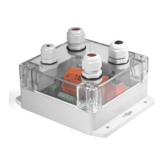
Page 8: Appearance
DTU4x0 GPRS/NB-IoT Data Loggers User Guide. r. 2.01 | 2022-05-17 Appearance DTU4x0 is a single-board microcontroller device in a sealed plastic IP65 case. DTU410, DTU420 (7-30 VDC power supply) DTU410-C, DTU420-C (100-240 VAC power supply) Tel.: +420 234 076 670 e-mail: info@adgt.cz... - Page 9 3.6V power is supplied programmatically, by pulses, with an input polling frequency. Connector type is a screw terminal block (pitch - 5.08 mm). Connector type is a screw terminal block (pitch - 3.81 mm). Tel.: +420 234 076 670 e-mail: info@adgt.cz...
-
Page 10: Dtu4X0 Interfaces And Wiring Diagrams
• • • • • Leakage sensor • • • • • • • • • • ADGT temperature sensor – • • • • • • • • • • – Engine hours sensor • • • •... - Page 11 (temperature sensors, leakage, magnetic impact, etc.). Threshold values of the resistance in closed and open states for this input type are set manually. Leakage sensor - the type of input used when connecting ADGT leakage sensor to data logger. •...
- Page 12 DTU4x0 GPRS/NB-IoT Data Loggers User Guide. r. 2.01 | 2022-05-17 1-Wire sensor - the type of input used when connecting an ADGT DS18B20 temperature • sensor to data logger. When the input is selected, a software configurable 5V power output of the Vout terminal block becomes active and turns on with an input polling frequency.
-
Page 13: Dtu4X0 Operating Modes
• When pressing S2 button – data logger setup/connection to the server button. • When a magnet is brought towards the case of data logger - DTU sends a message to the server. Tel.: +420 234 076 670 e-mail: info@adgt.cz... -
Page 14: Led Indication
All data was transferred during the session. ST2 and ST3 flash The indication is triggered at the end of the con- alternately for 3 seconds nection session if the connection was established by pressing the S2 button. Tel.: +420 234 076 670 e-mail: info@adgt.cz... -
Page 15: Collection And Storage Of Information
(included in the package) on the JP1 connector. When the external power is turned off, data logger immediately switches to battery power. When the external power is restored, the battery power is turned off. Tel.: +420 234 076 670 e-mail: info@adgt.cz... -
Page 16: Getting Started
Before starting the installation, you should add your data logger(-s) to https://iot24.eu cloud server by the IMEI number and PIN code (see on the label of the case): My projects -> Project name -> Building name -> Add Data Logger. Tel.: +420 234 076 670 e-mail: info@adgt.cz... -
Page 17: Installation And Connection
NOTE: SIM slots are located under the battery, so the battery must be removed to install the SIM cards. a) Cut a temporary plastic tie securing the battery, and put the battery aside. Tel.: +420 234 076 670 e-mail: info@adgt.cz... - Page 18 We Firmly fix the battery with a cable tie and recommend slightly bending the tip of cut off the excess tale. the cable tie to make it easier to pull it out. Tel.: +420 234 076 670 e-mail: info@adgt.cz...
- Page 19 Insert wires into the corresponding terminal connectors and tighten the screws to fix the wires. CAUTION! − P1-P11 – contacts “–” − 3.6V – contacts “+” Tel.: +420 234 076 670 e-mail: info@adgt.cz...
- Page 20 V pins of 7-30VDC connector, observing the correct polarity of the wires: CAUTION! Max. input voltage can not exceed 30V. Reverse polarity will not cause damage, but the data logger will not operate. Tel.: +420 234 076 670 e-mail: info@adgt.cz...
- Page 21 Wrap the wires with an insulation tape (included) to ensure the necessary sealing, and tighten the caps of cable glands. b) Tightly screw the cover to the base, evenly tightening screw connections. Tel.: +420 234 076 670 e-mail: info@adgt.cz...
-
Page 22: Firmware Update
2. In the DTU Configuration Tool, click the Service Functions button (1). 3. In the window that opens, click Open (2), select the .crt firmware file from the unzipped folder and click Start (3). After a successful firmware update, data logger will automatically reboot. Tel.: +420 234 076 670 e-mail: info@adgt.cz...
Need help?
Do you have a question about the DTU4 0 Series and is the answer not in the manual?
Questions and answers