Advertisement
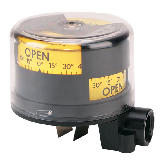
Series QV Quick-View
Specifications - Installation and Operating Instructions
Proximity Series QV Quick-View
Rotary Position Indicator/Switch is produced
®
with up to four individual mechanical or proximity switches. Instructions below include
installation, as well as adjustment procedures for direct drive and lever drive models.
INSTALLATION
1. Mounting kits, when provided include couplers, lever arms and screws for
mounting the position indicator to a valve or actuator. A position indicator is
mounted using direct drive hardware for quarter turn applications (rotational) and
lever drive hardware for converting linear motion to rotary. Tubular spacers are also
provided for some installations.
2. For direct drive models, attach appropriate drive yoke or solid block onto the two
pins, using a #6-32 X 1/4˝ screw provided. Do not attempt to fabricate your own
yokes since this a special spring-tempered material. For direct drives, with the
actuator shaft rotated to its counterclockwise position, spread the driving yoke and
slip it down onto the square (or rectangular) shaft of the actuator. Attach bracket
with two hex cap screws. Before tightening screws, operate control slowly with
a wrench or power, and observe that drive shaft and drive yoke are concentric and
perpendicular throughout the complete stroke. Adjust position as required and
tighten all mounting screws. Check concentricity and perpendicularity.
3. For lever drive models, attach the appropriate driving lever onto the shaft. Do
not tighten. Attach switch and bracket to actuator, making sure that the lever is
free to rotate over the entire range of the actuator stroke. Attach the driving pin
or bolt through the lever arm if slotted, or on the driving side of the lever. (It may
be necessary to loosen or remove the bracket mounting to accomplish this
connection on some actuators.) Operate the actuator very slowly and observe
movement of all pins and levers to be sure there are no interferences. Slide lever
up or down on switch shaft to the most desirable position. When all motions are
made and clearances are adequate, tighten clamp screw on lever that was left
loose above. Now tighten all the mounting screws. Re-check the travel of all levers
and pins for proper clearance throughout the complete stroke of the actuator.
4. Push cover down, then turn it counterclockwise and lift straight up to remove.
Remove inner cover window. Remove the indicator drum.
5. Switches are set at the factory in the counterclockwise position listed below:
2 Switch Unit
#1 Open
4 Switch Unit
#1, 3 Open
90° rotational travel will reverse all of the above positions.
DWYER INSTRUMENTS, INC.
P.O. BOX 373 • MICHIGAN CITY, INDIANA 46360, U.S.A.
#2 Closed
#2, 4 Closed
Rotary Position Indicator/Switch
®
3 [76.20] CLEARANCE REQUIRED FOR COVER REMOVAL
4-15/32
[113.5]
1/2
[12.70]
5/16
[7.938]
1/4 DIA. [6.350]
SHAFT LEVER
DRIVE ONLY
SPECIFICATIONS
Minimum Rotation Travel - Switches Only: 5°.
Maximum Rotation Travel - Switches Only: 360°.
Temperature Limits: -40 to 180°F (-40 to 82°C).
Switch Type: SPDT.
Electrical SPDT Switch Ratings: QV-X1XXXX: 10A @ 125/250 VAC; 0.5A 125
VDC; 10A @ 24 VDC mech. switch; QV-X2XXXX: 0.1A @ 125 VAC; 0.1A @ 24
VDC mech. switch; QV-X3XXXX: 2A @ 125 VAC; 2A @ 30 VDC prox. switch;
QV-X4XXXX: 5-25 VDC namur sensor; QV-X5XXXX: 10-30 VDC inductive sensor;
QV-X6XXXX: 10A 125/250 VAC mech. switch.
Lighting Supply Voltage: 24-28 VDC.
Enclosure Material: Polycarbonate housing and conduit.
Conduit Entrance: One 3/4˝ NPT.
Enclosure Rating: NEMA 4, 4X. Optional explosion-proof, rated: Class I, Groups A,
B, C, D; Class II, Groups F & G; Div. 2.
Max. Altitude: 2000 m (6560 ft).
Agency Approvals: CE, CSA, cULus.
MODEL CHART
Example
QV -2 1 01 0 1
Series
QV
Number of
0
Switches
1
2
3
4
Switch Type
0
1
2
3
4
5
6
Driving Style
Lighting
Option
Visual
Indication
Additional
Options
*EX, Explosion-proof option available.
Note: The 1st, 2nd, 3rd and 6th codes can not all be zero.
Phone: 219-879-8000
Fax: 219-872-9057
1/8 DIA. PINS (2)
4-3/4
[120.7]
6-32 UNC
1/4
1/4 DP [6.350]
[6.350]
CONDUIT ENTRANCE
3/4 NPT
QV-210101
Quick-View
valve position indicator/switch
®
None*
One*
Two*
Three*
Four*
No switches*
10A mechanical snap switch
1A mechanical gold contacts
2A Proximity reed switch*
5-25 VDC namur sensor
10-30 VDC inductive sensor
10A mechanical snap switch
01
Direct*
02
Lever*
03
Namur*
0
None*
1
24-28 VDC bright white LED's
0
None
1
Standard (open closed)*
2
Upside down (open closed)*
EX Class I, Div. II, Groups A, B, C & D; Class
II, Div. II Groups F & G.
www.dwyer-inst.com
e-mail: info@dwyermail.com
Bulletin F-87
2 MTG HOLES
1/4-20 UNC
7/16 DP [11.11]
1-1/2
[38.10]
1/4
[6.350]
2-3/8
[60.33]
3-1/16
[77.79]
Advertisement
Table of Contents

Related Manuals for ProxiMity Quick-View QV Series

Summary of Contents for ProxiMity Quick-View QV Series
- Page 1 Rotary Position Indicator/Switch is produced ® SPECIFICATIONS with up to four individual mechanical or proximity switches. Instructions below include Minimum Rotation Travel - Switches Only: 5°. installation, as well as adjustment procedures for direct drive and lever drive models. Maximum Rotation Travel - Switches Only: 360°.
- Page 2 ADJUSTMENT PROCEDURE 1. Using wrench or power, rotate the actuator shaft to extreme clockwise position for direct drive applications. For linear applications, operate actuator to full closed position. All switches should change to their appropriate functions. 2. The cam can be relocated and repositioned by loosening the set screw. To adjust manual cams grasp cam on knurled segment of cam surface.
Need help?
Do you have a question about the Quick-View QV Series and is the answer not in the manual?
Questions and answers