Sign In
Upload
Download
Table of Contents
Contents
Add to my manuals
Delete from my manuals
Share
URL of this page:
HTML Link:
Bookmark this page
Add
Manual will be automatically added to "My Manuals"
Print this page
×
Bookmark added
×
Added to my manuals
Manuals
Brands
Weinzierl Manuals
Gateway
KNX 886
Operation and installation manual
Weinzierl KNX 886 Operation And Installation Manual
Modbus rtu gateway with 250 data points
Hide thumbs
1
Table Of Contents
2
3
4
5
6
7
8
9
10
11
12
13
14
15
16
17
18
19
20
21
22
23
24
25
26
27
28
29
30
31
32
33
34
35
36
37
38
39
40
41
42
43
44
45
46
47
48
49
page
of
49
Go
/
49
Contents
Table of Contents
Bookmarks
Table of Contents
Table of Contents
Application
Installation and Connection
KNX Programming Mode
Manual Operation and Status Display
Reset to Factory Default Settings
Wiring Scheme
Pluggable Screw Terminals
Pin Assignment
ETS Database
Description
General Settings
Modbus Settings
Datapoints N - M
Channel Function "DPT 01 - Binary - 1 Bit
Channel Function "DPT 03 - Dimming - 4 Bit
Channel Function "DPT 05 - Percent - 1 Byte
Channel Function "DPT 05 - Configured - 1 Byte
Channel Function "DPT 05 - Unsigned - 1 Byte
Channel Function "DPT 06 - Signed - 1 Byte
Channel Function "DPT 07 - Configured - 2 Bytes
Channel Function "DPT 07 - Unsigned - 2 Bytes
Channel Function "DPT 08 - Signed - 2 Bytes
Channel Function "DPT 09 - Float - 2 Bytes
Channel Function "DPT 14 - Float - 4 Bytes
General Information
Advertisement
Quick Links
Download this manual
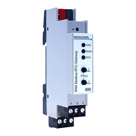
KNX Modbus Gateway with 250 data points
KNX Modbus RTU Gateway 886
Operation and installation manual
(Art. # 5256)
Weinzierl Engineering GmbH
Achatz 3
DE-84508 Burgkirchen / Alz
GERMANY
Tel: +49 (0)8677 / 91 636 – 0
info@weinzierl.de
www.weinzierl.de
© 2020 Weinzierl Engineering GmbH
Page 1/49
Table of
Contents
Previous
Page
Next
Page
1
2
3
4
5
Advertisement
Table of Contents
Need help?
Do you have a question about the KNX 886 and is the answer not in the manual?
Ask a question
Questions and answers
Related Manuals for Weinzierl KNX 886
Gateway Weinzierl KNX ENO 634 Manual
Bidirectional-gateway between enocean and knx-bus (11 pages)
Gateway WEINZIERL KNX IP BAOS 777 Operation And Installation Manual
Interface and objectserver between lan and knx bus (10 pages)
Gateway WEINZIERL KNX RF/TP Coupler 670 Installation And Operating Manual
Bidirectional gateway between knx-rf and the knx-bus (4 pages)
This manual is also suitable for:
5256
Table of Contents
Print
Rename the bookmark
Delete bookmark?
Delete from my manuals?
Login
Sign In
OR
Sign in with Facebook
Sign in with Google
Upload manual
Upload from disk
Upload from URL


Need help?
Do you have a question about the KNX 886 and is the answer not in the manual?
Questions and answers