
Summary of Contents for NAVIS NAVIOR-24S
- Page 1 Design Research Lab NAVIS GPS / GLONASS Time synchronization OEM Module NAVIOR-24S ™ System Designer Reference Manual...
- Page 2 This document contains proprietary technical information which is the property of Design Research Lab Navis, copying of this document and giving it to others and the using or communication of the contents thereof, are forbidden without express authority. Offenders are liable to the payment of damages.
-
Page 3: Table Of Contents
Pulse-Per-Second (PPS) ......................39 Status ............................40 Mounting ............................41 GPS/GLONASS Antennas......................42 III. Software Interface ........................44 Start-up ............................45 Communicating with the NAVIOR-24S GPS/GLONASS Receiver........46 Software Tools ...........................46 Port Configuration........................46 Port Protocol and Data Output Options..................47 Custom Port Configuration ......................48 Timing Applications........................49 Operation and Performance....................50 Introduction ..........................51... - Page 4 DGNSS Off ..........................59 Position Accuracy.........................60 Coordinate Systems........................61 Performance Characteristics.......................62 Update Rate ..........................62 Dynamic Limits..........................62 Re-Acquisition ...........................62 NAVIOR-24S GPS/GLONASS Receiver interference mask ...........63 GPS/GLONASS Timing ......................64 Pulse-Per-Second (PPS) .......................65 PPS Output Mode........................65 Always Off ..........................65 Always On (default) ........................65 Fix Based............................65 Programmable Characteristics - Signal Offset (Cable Delay Compensation) ......66...
- Page 5 NAVIOR-24S ™ System Designer Reference Manual Receiver extra settings .......................87 Disable transmission of all data ....................92 Almanac data..........................93 Ephemeris data ...........................98 Satellites using..........................103 Visible satellites ........................105 Receiver channels measurements.....................107 Used satellites & DOP......................110 Receiver channels control ......................112 PVT solution ..........................114 Local time zone ........................116...
- Page 6 The STATISTIC window......................205 The KINEMATIC window ......................206 The VISUAL window ......................207 The PROFILE window......................209 Data accumulation........................210 Reading data from file......................211 STOREGIS messages.......................212 STOREGIS Preferences ......................213 Specifications and Mechanical Drawings................214 NAVIOR-24S GPS/GLONASS Receiver Specifications............215 Key Features..........................215 NAVIOR-24S ™ Revision V1.00 20.05.2008...
- Page 7 NAVIOR-24S ™ System Designer Reference Manual Performance ..........................216 Interface............................217 Accessories..........................218 Glossary..........................220 NAVIOR-24S ™ Revision V1.00 20.05.2008...
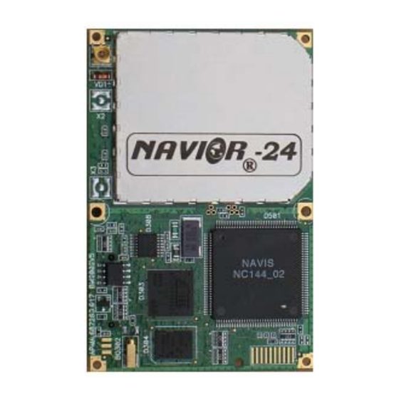
- Page 8 NAVIOR-24S ™ System Designer Reference Manual Figure Index Figure I-1 NAVIOR-24S GPS/GLONASS receiver module ............18 Figure I-2 Starter Kit front panel view ..................20 Figure I-3 Starter Kit rear panel view ..................21 Figure I-4 AC/DC Power Converter....................22 Figure I-5 Starter Kit Interface Unit....................28 Figure II-1 –...
- Page 9 NAVIOR-24S ™ System Designer Reference Manual Figure IV-32. The VISUAL window.....................207 Figure IV-33. The VISUAL window.....................208 Figure IV-34. The PROFILE window ..................209 Figure IV-35. Numeration of X501 connector pins..............218 Figure IV-36. NAVIOR-24S GPS/GLONASS Receiver. Mechanical drawings.......219 NAVIOR-24S ™ Revision V1.00 20.05.2008...
- Page 10 NAVIOR-24S ™ System Designer Reference Manual Table Index Table I-1 - NAVIOR-24S GPS/GLONASS Receiver Ordering Information ......17 Table I-2 - Port “COM 1” pin designation ..................23 Table I-3 - Port “COM 2” pin designation ..................24 Table I-4 - Port “COM3” pin designation ..................25 Table II-1 - Logic levels of serial port pins ..................32...
- Page 11 NAVIOR-24S ™ System Designer Reference Manual Version History Data Version What is News Author 20.05.2008 01.00 Original Prokopyuk NAVIOR-24S ™ Revision V1.00 20.05.2008...
-
Page 12: Starter Kit
NAVIOR-24S ™ CHAPTER 1 Starter Kit I. Starter Kit Product Overview Starter Kit Receiver Performance Interface Protocols Ordering Starter Kit Components Starter Kit Interface Unit Power Connectors Hardware Setup Software Toolkit NAVIOR-24S ™ Revision V1.00 20.05.2008... -
Page 13: Product Overview
Starter Kit Product Overview NAVIOR-24S™ is GPS / GLONASS navigation sensor board to be used in a broad spectrum of original equipment manufacturer (OEM) system applications to provide precise clocks using the signals from GPS, GLONASS satellite navigation systems according to UTC, UTC SU, GPS and GLONASS time scale. -
Page 14: Starter Kit
Starter Kit Starter Kit The Starter Kit makes it simple to evaluate the NAVIOR-24S GPS/GLONASS receiver’s exceptional performance. The Starter Kit can be used as a platform for configuring the receiver module and as a platform for troubleshooting your design. The Starter Kit includes: •... -
Page 15: Receiver Performance
The NAVIOR-24S GPS/GLONASS receiver is a complete 24-channel parallel tracking GPS/GLONASS/SBAS receiver designed to operate with the L1 frequency, Standard Position Service, C/A code for GPS and CT code for GLONASS. Using three highly integrated NAVIS custom integrated circuits, the receiver is designed in format for embedded applications. -
Page 16: Interface Protocols
NAVIOR-24S ™ CHAPTER 1 Starter Kit Interface Protocols The NAVIOR-24S GPS/GLONASS receiver operates using one of three protocols — BINR or NMEA 0183. Protocol selection and port characteristics are user configurable. The factory default settings are: • Port 1, NMEA 0183 •... -
Page 17: Ordering Starter Kit Components
Antenna M102 .464651.002 Antenna installation facilities А.464961.001 Antenna installation facilities А.464961.002 Board-to-board connector TFM-110-12-S-D-A, Samtec CD-ROM А.467616.006 Note – Part numbers are subject to change. Confirm part numbers with your NAVIS representative when placing your order. NAVIOR-24S ™ Revision V1.00 20.05.2008... -
Page 18: Starter Kit Interface Unit
The metal enclosure protects the module and the motherboard for testing outside of the laboratory environment. The RF part of the NAVIOR-24S GPS/GLONASS receiver is encased in a sturdy metal enclosure. The dimensions of the receiver in this enclosure are 50 mm (W) x 75 mm (L) x 12 mm (H). A straight-in, panel-mount RF connector (X1) supports the GPS/GLONASS antenna connection. - Page 19 NAVIOR-24S ™ CHAPTER 1 Starter Kit The interface motherboard includes a 7 to 15 VDC switching power supply which provides regulated +3.3 VDC power to the receiver, and contains circuitry which provides two RS-232 interface ports and RS-485 port for 1PPS. A 3.0V lithium backup battery enables quick warm starts.
- Page 20 NAVIOR-24S ™ CHAPTER 1 Starter Kit Figure I-2 Starter Kit front panel view NAVIOR-24S ™ Revision V1.00 20.05.2008...
- Page 21 NAVIOR-24S ™ CHAPTER 1 Starter Kit Figure I-3 Starter Kit rear panel view NAVIOR-24S ™ Revision V1.00 20.05.2008...
-
Page 22: Power
Starter Kit Power NAVIOR-24S GPS/GLONASS receiver is designed for embedded applications and requires a regulated +3.3 VDC input (+3.20 to +3.45 VDC). The receiver, provided in the Starter Kit, is installed on a motherboard, providing a DC power regulator which converts from 7 to 15 VDC input to the regulated 3.3 VDC required by the receiver. -
Page 23: Connectors
NAVIOR-24S ™ CHAPTER 1 Starter Kit Connectors COM 1 Port “COM 1” is intended for ensuring RS-232 user interface. The type of connector is DB-9F. Port “COM 1” pin designation is listed in Table I-2. By default, port “COM 1”is adjusted to BINR protocol, an exchange velocity by default is 19200 baud. -
Page 24: Com 2
NAVIOR-24S ™ CHAPTER 1 Starter Kit COM 2 Port “COM 2” is intended for ensuring RS-232 user interface. The type of connector is DB-9F. Port “COM 2” pin designation is listed in Table I-3. By default, port “COM 2”is adjusted to NMEA- 0183 protocol, an exchange velocity by default is 9600 baud. -
Page 25: Com 3
NAVIOR-24S ™ CHAPTER 1 Starter Kit COM 3 Port “COM 3” is intended for ensuring RS-422 user interface. The type of connector is DB-15F. Port ”COM 3” pin designation is listed in Table I-4. Table I-4 - Port “COM3” pin designation... -
Page 26: Power
NAVIOR-24S ™ CHAPTER 1 Starter Kit Power “PОWЕR” – is intended for power supply connection from+7 up to +15 VDC. The type of connector is – DJK-05D. The central contact is positive. Note - The alternative power connection may be used with using port COM3. See Table I-4. -
Page 27: Antenna
Starter Kit Antenna “ANT” is adjusted to connect an external antenna to NAVIOR-24S. The type of connection is R143 324 000 “RADIALL” (male). An active antenna power supply with 3,3 VDC nominal rating with input current at most 60 mA. -
Page 28: Hardware Setup
Starter Kit Hardware Setup The NAVIOR-24S GPS/GLONASS receiver supports the BINR and NMEA protocols. A single port supports both the input/output of BINR messages and the output of NMEA messages. Follow the steps below to setup the Starter Kit interface unit. Figure I-5 illustrates the setup. -
Page 29: Software Toolkit
The CD provided in the Starter Kit contains the BM_Ctrl and the STOREGIS, interface programs used to monitor GPS/GLONASS performance and to assist system integrators in developing a software interface for the NAVIOR-24S GPS/GLONASS module. These applications are described in detail in Appendix C, BINR User's Guide and Appendix D NMEA User's Guide BM_Ctrl and the STOREGIS run on the Windows 95/98/2000/XP platforms. - Page 30 Note – If there is no connection, GPS/GLONASS module may not be communicated with the computer. Re-check the interface cable connections and verify the serial port selection and settings. If the communication failure continues after checking all connections and settings, please call the NAVIS Technical Assistance Center. NAVIOR-24S ™ Revision V1.00...
-
Page 31: Ii. Hardware Integration
NAVIOR-24S ™ CHAPTER II Hardware Integration II. Hardware Integration General Description Connectors Power Requirements Serial Interface Serial Port Connections Pulse-Per-Second (PPS) Mounting GPS Antennas NAVIOR-24S ™ Revision V1.00 20.05.2008... -
Page 32: General Description
Hardware Integration General Description NAVIOR-24S provides asynchronous serial port. NAVIOR-24S module is designed as a DCE (Data Communication Equipment), following the traditional DCE-DTE (Data Terminal Equipment) connection, the module and the client (DTE) are connected through the following signal (as Figure II-1 shows). -
Page 33: Connectors
Hardware Integration Connectors Digital IO/Power Connector The NAVIOR-24S GPS/GLONASS module uses a single 20-pin (2x10) female connector for both power and data I/O. The power and I/O connector is X501. The manufacturer of this connector is Samtec, part number SFM-110-02-S-D-A. -
Page 34: Digital Io/Power Connector Pin Out
NAVIOR-24S ™ CHAPTER II Hardware Integration Digital IO/Power Connector Pin out The digital IO/Power connector pin out information is listed in Table II-2. Table II-2 - X501 I/O Connector Signals Name Direction Description Input Prime Power (VCC) Ground signals and power... -
Page 35: Power Requirements
10 μF tantalum capacitor (low ESR) with a small (0.1 μF to 1 μF) ceramic in parallel. And the capacitors should put as closer as possible to the NAVIOR-24S VCC pins. The receiver does not require any special power up or down sequencing. The receiver power is supplied through pin 1, 3 of the I/O connector. -
Page 36: Battery Back-Up
Note – 2.0 V is the minimum allowable battery back-up voltage. When the battery back-up power output drops below 2.0 V, the real-time clock may not operate over the specified temperature range. This can also significantly extend the time to first fix. NAVIS does not recommend the use of Super Caps as battery back-up. -
Page 37: Serial Interface
TTL level serial I/O. The RX and TX signals on the X501 I/O connector are driven directly by the UART on the NAVIOR-24S GPS/GLONASS receiver. Interfacing these signals directly to a UART in your application circuitry provides direct serial communication without the complication of RS-232 or RS-422 line drivers. -
Page 38: Serial Port Connections
NAVIOR-24S ™ CHAPTER II Hardware Integration Serial Port Connections Figure II-2 shows the Serial port connection. Figure II-2 – Serial port connection Note - If you want to use a synchronous system connect the Reset signal to pin 17 Digital IO/Power Connector Pin out of the receiver. -
Page 39: Pulse-Per-Second (Pps)
PPS is output immediately after main power is applied, and continues even if the receiver loses GPS clock. The drift of the PPS, when the NAVIOR-24S GPS/GLONASS receiver is not tracking satellites, is unspecified and should not be used for synchronization. -
Page 40: Status
Hardware Integration Status Signal status may be used for indicating operation modes of NAVIOR-24S receiver (for example – LED display). STATUS = «0» - when a low level is on the out of pin STATUS it means the absence of reliable 1PPS signal. -
Page 41: Mounting
CHAPTER II Hardware Integration Mounting The NAVIOR-24S GPS/GLONASS PCB is RF section, encased in a metal enclosure. The enclosure acts as a protective case of RF section. The NAVIOR-24S GPS/GLONASS module can be attached to the integrator platform using Surface-Mount Mating Connector. Recommended surface mount mating connector is Samtec’s part number TFM-110-xx-S-D, when xx –... -
Page 42: Gps/Glonass Antennas
1. A Compact Magnetic-Mount GPS/GLONASS Antenna with a 5 m cable and TNC or SMA connector. This antenna provides for a flexible, movable installation. The TNC or SMA output connector mates to the MMCX connector on the NAVIOR-24S GPS module with an optional RF transition cable. - Page 43 NAVIOR-24S ™ CHAPTER II Hardware Integration 2. A Maritime GPS/GLONASS Antenna without cable and TNC connector. A Maritime GPS/GLONASS Antenna is ideal for objects when antenna is mounted far away (up to 100 meters) Figure II-4 – Maritime GPS/GLONASS Antenna NAVIOR-24S ™...
-
Page 44: Iii. Software Interface
NAVIOR-24S ™ CHAPTER III Software Interface III. Software Interface Start-up Communicating with the NAVIOR-24S GPS/GLONASS Receiver Software Tools Port Configuration Port Protocol and Output Options Custom Port Configuration Timing Applications NAVIOR-24S ™ Revision V1.00 20.05.2008... -
Page 45: Start-Up
Note – See Chapter 4 for further detail on ephemeris data and the GPS and GLONASS almanac. Warning – The NAVIOR-24S GPS/GLONASS Receiver is ready to accept any commands approximately 6 seconds after power-up. If a command is sent to the receiver within this 6 second window, the receiver will ignore the command. -
Page 46: Communicating With The Navior-24S Gps/Glonass Receiver
NAVIS Standard Interface. Port Configuration The NAVIOR-24S GPS/GLONASS receiver module has two I/O ports. Table III-1 provides the default protocols and port configurations for the receiver, as delivered from the factory. NMEA- OUT is the default protocol on Port 1 and BINR IN/OUT is the default protocol on Port 2. -
Page 47: Port Protocol And Data Output Options
NAVIOR-24S ™ CHAPTER III Software Interface Port Protocol and Data Output Options The “1PPS” temporal diagram and digitizing, given out in the 72h package of BINR protocol, is shown on Figure III-1. Figure III-1. The “1PPS” temporal diagram and digitizing, given out in the 72h package of BINR protocol The “1PPS”... -
Page 48: Custom Port Configuration
The user may change port adjustments using protocol BINR or NMEA. Using BINR packet 0Bh the user may change port adjustments (see Appendix A). SW BM_Ctrl also can be used to customize the NAVIOR-24S GPS/GLONASS receiver configuration port settings (see Appendix В). -
Page 49: Timing Applications
Software Interface Timing Applications The NAVIOR-24S GPS/GLONASS receiver is an excellent source for accurate system timing. Four examples of applications requiring accurate time are environmental data acquisition and synchronization of communications networks. The timing functions of the receiver are supported by the BINR protocol and the PPS signal. -
Page 50: Iv. Operation And Performance
Averaging mode Differential GPS Operating Modes Differential GPS Operatio DGPS On] DGPS Off Position Accuracy Coordinate Systems Performance Characteristics Update Rate Dynamic Limits Re-acquisition NAVIOR-24S GPS/GLONASS Receiver interference mask GPS/GLONASS Timing Pulse-Per-Second (PPS) System Architecture NAVIOR-24S ™ Revision V1.00 20.05.2008... -
Page 51: Introduction
The receiver automatically selects and tracks the best combination of satellites to compute position and velocity. As satellites move out of view, the NAVIOR-24S GPS/GLONASS receiver automatically acquires new satellites and includes them in the solution set as required. -
Page 52: Gps Satellite Message
Ephemeris data changes hourly, but is valid for up to four hours. The GPS control segment updates the system almanac weekly and the ephemeris hourly through three ground-based control stations. During normal operation, the NAVIOR-24S GPS/GLONASS receiver module updates its ephemeris and almanac as needed. -
Page 53: Glonass Satellite Message
NAVIOR-24S ™ CHAPTER IV Operation and Performance GLONASS Satellite Message Satellite message is transmitted as numerical data flow encoded in Hemming code and converted into relational code. Structurally the data flow is formed as continuously repeated super frames. The super frame consists of 5 frames. The frame consists of 15 data lines. -
Page 54: Satellite Acquisition And Time To First Fix
As satellites are acquired, the receiver automatically collects ephemeris and almanac data. The NAVIOR-24S GPS/GLONASS receiver uses the knowledge gained from acquiring a specific satellite to eliminate other satellites, those below the horizon, from the search set. -
Page 55: Warm Start
During a warm start, the NAVIOR-24S GPS/GLONASS receiver identifies the satellites which are expected to be in view, given the system almanac, the initial position and the approximate time. The receiver calculates the elevation and expected Doppler shift for each satellite in this expected set and directs the eight tracking channels in a parallel search for these satellites. -
Page 56: Satellite Mask Settings
Operation and Performance Satellite Mask Settings Once the NAVIOR-24S GPS/GLONASS receiver has acquired and locked onto a set of satellites, which pass the mask criteria listed in this section, and has obtained a valid ephemeris for each satellite, it will output regular position, velocity and time reports according to the selected protocol. -
Page 57: Elevation Mask
NAVIOR-24S ™ CHAPTER IV Operation and Performance Elevation Mask Satellites which are below a 5° elevation are not used in the position solution. Although low elevation satellites can contribute to a lower PDOP, the signals from low elevation satellites have poorer quality, since they suffer greater tropospheric and ionospheric distortion than the signals from higher elevation satellites. -
Page 58: Standard Operating Modes
5 m. In this mode an antenna coordinates must be specified and the NAVIOR-24S must be transferred in fixed position mode. It is the most exact mode as only time determination with taking a known position into account executes in the navigation task. -
Page 59: Dgnss Operating Modes
Operation and Performance DGNSS Operating Modes The default mode for the NAVIOR-24S GPS/GLONASS receiver is off by Differential DGNSS Operating Mode. The receiver supports two DGNSS Modes: On, Off. The mode may be changed by issuing the appropriate BINR command (see Appendix A for details). -
Page 60: Position Accuracy
NAVIOR-24S ™ CHAPTER IV Operation and Performance Position Accuracy Position accuracy is degraded by atmospheric distortion, satellite geometry, satellite clock errors, and receiver clock errors. Effective models for atmospheric distortion of satellite signals have been developed to minimize the impact of tropospheric and ionospheric effects. The impact of satellite clock errors is minimized by incorporating the clock corrections transmitted by each satellite used in the position solution. -
Page 61: Coordinate Systems
Operation and Performance Coordinate Systems After the NAVIOR-24S GPS/GLONASS receiver achieves its first fix, it is ready to commence output of position, velocity, and time information. This information is output over serial communication channel in either the BINR or NMEA protocol, as determined by the settings of the receiver. -
Page 62: Performance Characteristics
$PORZB (see Appendix С). Dynamic Limits The dynamic operating limits for the NAVIOR-24S GPS/GLONASS receiver are listed below. These operating limits assume that the GPS/GLONASS module is correctly embedded and that the overall system is designed to operate under the same dynamic conditions. -
Page 63: Navior-24S Gps/Glonass Receiver Interference Mask
NAVIOR-24S ™ CHAPTER IV Operation and Performance NAVIOR-24S GPS/GLONASS Receiver interference mask NAVIOR-24S GPS/GLONASS Receiver with antenna M102 provides interference mask immunity, shown on Figure IV-1. -100 -120 -140 -160 1315 1525 1562 1584 1593 1609 1614 1635 2000 2500 GLONASS Figure IV-1. -
Page 64: Gps/Glonass Timing
GPS receivers use the signals from these GPS “clocks” to correct its internal clock, which is not as stable or accurate as the GPS atomic clocks. GPS receivers like the NAVIOR-24S GPS/GLONASS receiver output a highly accurate timing pulse (PPS) generated by its internal clock, which is constantly corrected using the GPS clocks. -
Page 65: Pulse-Per-Second (Pps)
GPS time from the satellite and is obtaining fixes. The PPS is output immediately after main power is applied, and continues even if the receiver loses GPS lock. The drift of the PPS, when the NAVIOR-24S GPS/GLONASS receiver is not tracking satellites, is unspecified and should not be used for synchronization. -
Page 66: Programmable Characteristics - Signal Offset (Cable Delay Compensation)
PPS offset parameter of the PPS definition packet (D7h). Note – Navis has measured less than 50 nanoseconds accuracy of the NAVIOR-24S GPS/GLONASS receiver PPS signal in static mode. For more information on timing applications, contact your Navis sales representative. -
Page 67: System Architecture
Operation and Performance System Architecture The NAVIOR-24S GPS/GLONASS receiver uses 24 processing channels operating on the GPS L1 frequency of 1575.42 MHz and using the coarse acquisition (C/A) code and GLONASS L1 frequency band of 1598,0625…1605,375 MHz and using the coarse CT code . The module uses custom integrated circuitry designed by NAVIS to track the GPS/GLONASS satellite signals. -
Page 68: Navis Standard Interface Protocol Binr
GNSS navigation receiver for optimum performance in a variety of applications. The BINR protocol is used especially in the NAVIS navigation receivers. This protocol is based on the transmission of packets of information between the user equipment and the unit. Each packet includes an identification code (1 byte, representing 2 hexadecimal digits) that identifies the meaning and format of the data that follows. -
Page 69: Communication Line
NAVIOR-24S ™ Appendix A Navis Standard Interface Protocol BINR Communication line Bi-directional serial interface RS-232 (COM-port) uses as communication line for BINR protocol. Connection is based on the null modem chart (used only 3 lines: receive, transmit and common (GND)). The next COM-port settings required for normal operation mode:... -
Page 70: Packet Structure
NAVIOR-24S ™ Appendix A Navis Standard Interface Protocol BINR Packet Structure BINR packets structure is the same for both commands and reports. The packet format is: <DLE> <id> <data string bytes> <DLE> <ETX> Where: <DLE> is the byte 0x10 <ETX> is the byte 0x03 <id>... -
Page 71: Used Data Types
NAVIOR-24S ™ Appendix A Navis Standard Interface Protocol BINR Used data types Multiple-byte numbers follow the ANSI/IEEE Std. 754 IEEE Standard (see Table IV-3) Table IV-3 Data types format Data type Dimension, bits Values range INT8U 0…255 INT8S -128…127 INT16U 0…65,535... -
Page 72: Navis Standard Interface Protocol Binr
GNSS navigation receiver for optimum performance in a variety of applications. The BINR protocol is used especially in the NAVIS navigation receivers. This protocol is based on the transmission of packets of information between the user equipment and the receiver. Each packet includes an identification code (1 byte, representing 2 hexadecimal digits) that identifies the meaning and format of the data that follows. -
Page 73: Used Data Types
NAVIOR-24S ™ Appendix B Navis Standard Interface Protocol BINR The bytes in the data string can have any value. To prevent confusion with the frame sequences <DLE> <ID> and <DLE> <ETX>, every <DLE> byte in the data string is preceded by an extra <DLE>... -
Page 74: Packets Binr
NAVIOR-24S ™ Appendix B Navis Standard Interface Protocol BINR Packets BINR Port Parameters Set/Request Packet 0Bh Packet 0Bh requests or sets the protocol type and port parameters. Data exchange rate can be selected in the range from 4800 up to 115200 bauds. - Page 75 NAVIOR-24S ™ Appendix B Navis Standard Interface Protocol BINR Get Packet 50h Get packet 50h has following structure: – port number: 01 – port No1 02 – port No2 Data type format - INT8U – rate of exchange: C0 12 00 00 – 4800 b/s 80 25 00 00 –...
-
Page 76: Check Connection
NAVIOR-24S ™ Appendix B Navis Standard Interface Protocol BINR Check connection Request Packet 26h Request packet 26h provides control of the external communication. It has following structure: NAVIOR-24S ™ Revision V1.00 20.05.2008... - Page 77 NAVIOR-24S ™ Appendix B Navis Standard Interface Protocol BINR Answer Packet 54h A single transmission of packet 54h confirms the availability of the external communication. It has following structure: NAVIOR-24S ™ Revision V1.00 20.05.2008...
-
Page 78: Reset/Restart Receiver
NAVIOR-24S ™ Appendix B Navis Standard Interface Protocol BINR Reset/Restart receiver Packet 01h. Restart command. Packet 01h fulfills the forced system restart either with NVRAM data deletion or without data deletion. - constant data of the package Data type format - INT8 - almanac Data Storages 00 –... -
Page 79: Sw Version Info
NAVIOR-24S ™ Appendix B Navis Standard Interface Protocol BINR SW version info Request Packet 1Bh Packet 1Bh requests SW version. Packet 70h is the get packet. Packet 1Bh contains no data and has following structure: NAVIOR-24S ™ Revision V1.00 20.05.2008... - Page 80 NAVIOR-24S ™ Appendix B Navis Standard Interface Protocol BINR Get Packet 70h Packet 70h contains receiver channels quantity information and information about HW and SW versions. It has following structure: - receiver channels quantity Data type format - INT8U - SW version and receiver ID (data length - 21 byte) Data type format - INT8U - receiver reference number (data length –...
-
Page 81: Receiver Test
NAVIOR-24S ™ Appendix B Navis Standard Interface Protocol BINR Receiver test Start/Request Packet 11h Packet 11h enables the receiver testing or repetition of test results transmission. The test is performed each time you turn the receiver on. 00 – to request test results 01 –... - Page 82 NAVIOR-24S ™ Appendix B Navis Standard Interface Protocol BINR Get status/results Packet 43h Packet 43h is transmitted in three cases: at power up, at confirmation of test starting and at transmission of test results The get type: 00 – after power up 01 –...
-
Page 83: Receiver Settings
NAVIOR-24S ™ Appendix B Navis Standard Interface Protocol BINR Receiver settings Set/Request Packet 0Dh The package inquires or sets the following work characteristics of receiver: - coordinate system; - working SNS; - adjustments of PVT solution; The package does not contain data for request. The sets are fulfilled according to the data type indicated in the first parameter. - Page 84 NAVIOR-24S ™ Appendix B Navis Standard Interface Protocol BINR Work SNS set - work SNS set Data type format - INT8U - work SNS: 00 – GPS&GLONASS 01 – only GPS 02 – only GLONASS 0A – GPS&GLONASS&SBAS 0B – GPS&SBAS 0C –...
- Page 85 NAVIOR-24S ™ Appendix B Navis Standard Interface Protocol BINR Get Packet 51h The operation parameters setting must correspond to data type: data type 1: setting of coordinate system. data type 2: setting of satellite navigation system; data type 3: setting of navigation task;...
- Page 86 NAVIOR-24S ™ Appendix B Navis Standard Interface Protocol BINR - elevation mask Data type format - INT8U - reserved Data type format - INT8U - maximal RMS Data type format – INT16U - reserved Data type format – FP32 Note: Get packet 51h provides the current operation parameters. The default settings are: - working SNS: GPS&GLONASS...
-
Page 87: Receiver Extra Settings
NAVIOR-24S ™ Appendix B Navis Standard Interface Protocol BINR Receiver extra settings Set/Request Packet D7h Packet D7h requests or sets the following additional operation parameters: a) PVT solution rate; b) 1PPS control; c) signal delay in antenna cable; d) operation mode;... - Page 88 NAVIOR-24S ™ Appendix B Navis Standard Interface Protocol BINR 1PPS control To set the 1PPS parameters (in the example below: synchronization with the UTC, pulse duration 0.5 msec) packet D7h must have following structure: - data type: 1PPS control Data type format - INT8U - 1A –...
- Page 89 NAVIOR-24S ™ Appendix B Navis Standard Interface Protocol BINR Operation mode Packet D7h enables following operation parameters: - RAIM: on/off - solution 2D: enabled/disabled - satellite acceptance: accepted/refused. It has following structure: - data type: operation mode Data type format - INT8U...
- Page 90 NAVIOR-24S ™ Appendix B Navis Standard Interface Protocol BINR SNS priority Priority settings of navigation system. For example below: - GLONASS-channels: 11; - GPS-channels: 11; - SBAS-channels: 2. The packet has following structure: - data type: SNS priority Data type format - INT8U...
- Page 91 NAVIOR-24S ™ Appendix B Navis Standard Interface Protocol BINR Get Packet E7h Get packet E7h repeats the inserted data. NAVIOR-24S ™ Revision V1.00 20.05.2008...
-
Page 92: Disable Transmission Of All Data
NAVIOR-24S ™ Appendix B Navis Standard Interface Protocol BINR Disable transmission of all data Disable command. Packet 0Eh Packet 0Eh is used for clearing the list of transmitted packets NAVIOR-24S ™ Revision V1.00 20.05.2008... -
Page 93: Almanac Data
NAVIOR-24S ™ Appendix B Navis Standard Interface Protocol BINR Almanac data Load/Request Packet 20h Packet 20h requests the host or loads it with the almanac of one satellite. When requesting GPS-satellite almanac (i.e. SV No.1), it has following structure: - navigation system 01 –... - Page 94 NAVIOR-24S ™ Appendix B Navis Standard Interface Protocol BINR Get Packet 40h Get packet 40h, containing the almanac of GPS-satellite, has following structure: navigation system format (GPS in the example given above) 01 – GPS 02 – GLONASS Data type format - INT8U - SV No (1÷32)
- Page 95 NAVIOR-24S ™ Appendix B Navis Standard Interface Protocol BINR - perigee argument, radians Data type format – FP32 - mean anomaly of the reference time, radians Data type format – FP32 - time correction, msec Data type format – FP32 - time correction (polynomial factor), msec/msec Data type format –...
- Page 96 NAVIOR-24S ™ Appendix B Navis Standard Interface Protocol BINR Get packet 40h (the almanac of GLONASS-satellite given below) has following structure: navigation system format (GLONASS in the example given above) 01 – GPS 02 – GLONASS Data type format - INT8U - SV No (1÷24)
- Page 97 NAVIOR-24S ™ Appendix B Navis Standard Interface Protocol BINR - correction to the mean value of Draconian period, msec/circuit Data type format - FP32 - day No. within a 4-year time period Data type format – INT16U NAVIOR-24S ™ Revision V1.00...
-
Page 98: Ephemeris Data
NAVIOR-24S ™ Appendix B Navis Standard Interface Protocol BINR Ephemeris data Load/Request Packet 19h Packet 19h provides the request or loading ephemeris data for required satellite. Packet 19h enables transmission of all available ephemeris and their updates. For request all available ephemeris and their updates, packet 19h must have following structure: 00 –... - Page 99 NAVIOR-24S ™ Appendix B Navis Standard Interface Protocol BINR Get Packet 49h Packet 49h provides request, receipt and/or update of the ephemeris (every half-hour for the GLONASS and every hour for the GPS). - SNS system: (GPS in the example above) 01 –...
- Page 100 NAVIOR-24S ™ Appendix B Navis Standard Interface Protocol BINR - sine correction of argument of latitude, rad Data type format – FP32 - square root of a host axle, m Data type format – FP64 - ephemeris reference time, msec Data type format –...
- Page 101 NAVIOR-24S ™ Appendix B Navis Standard Interface Protocol BINR - measurement accuracy of distance by user Data type format – INT16U - ephemeris kit identifier Data type format – INT16U - SNS system:(GLONASS in the example above) 01 – GPS 02 –...
- Page 102 NAVIOR-24S ™ Appendix B Navis Standard Interface Protocol BINR Data type format – FP64 acceleration, m/msec Data type format – FP64 acceleration, m/msec Data type format – FP64 - time domain in current day, msec Data type format – FP64 - relative deviation of carrier frequency value of a signal Data type format –...
-
Page 103: Satellites Using
NAVIOR-24S ™ Appendix B Navis Standard Interface Protocol BINR Satellites using Packet 12h. Allow/Forbid satellite using. Packet 12h requests the data on the involved GPS/GLONASS-satellites and accepts or refuses use of a satellite for the task processing. - satellite system Data type format –... - Page 104 NAVIOR-24S ™ Appendix B Navis Standard Interface Protocol BINR Packet 47h. Satellite using confirmation. Get packet 47h provides data for 32 GPS-satellites and 24 GLONASS-satellites: - satellite system Data type format - INT8U - SV No 1–32 – for GPS 1 –...
-
Page 105: Visible Satellites
NAVIOR-24S ™ Appendix B Navis Standard Interface Protocol BINR Visible satellites Request Packet 24h Packet 24h requests the visible satellites data. 00 – disable packet transmission from 01 to 255 – setting transmission temp (in hexadecimal system) Data type format - INT8U NAVIOR-24S ™... - Page 106 NAVIOR-24S ™ Appendix B Navis Standard Interface Protocol BINR Get Packet 52h Get packet 52h contains azimuth and altitude for each visible satellite. It is also provided satellite SNR, which are tracked during the time of packet transmission. - navigation system format...
-
Page 107: Receiver Channels Measurements
NAVIOR-24S ™ Appendix B Navis Standard Interface Protocol BINR Receiver channels measurements Request Packet D4h Packet D4h enables/disables transmission of E4h packet, which contains measurements data of all receiver channels. 00 – disable packet transmission from 01 to 255 – transmission temp (in hexadecimal system) Data type format - INT8U NAVIOR-24S ™... - Page 108 NAVIOR-24S ™ Appendix B Navis Standard Interface Protocol BINR Get Packet E4h Get packet E4h contains data of time and measurements of receiver channels. It has following structure (in the packet which is shown below: data for 2 receiver channels): - measurement interval, msec Data type format –...
- Page 109 NAVIOR-24S ™ Appendix B Navis Standard Interface Protocol BINR - GLONASS-letter Data type format - INT8S - SNR Data type format - INT8U - indication of pseudo-range measurements availability Data type format - INT8U - pseudo-range data, msec Data type format – FP64 - range increase or Doppler integral under the measurement interval, Hz Data type format –...
-
Page 110: Used Satellites & Dop
NAVIOR-24S ™ Appendix B Navis Standard Interface Protocol BINR Used satellites & DOP Request Packet 21h Packet21h requests number of involved to PVT GPS and GLOASS satellites. It also requests values of HDOP/VDOP. 00 – disable packet transmission FF – transmission temp (from 01 to 255 in hexadecimal system) Data type format - INT8U NAVIOR-24S ™... - Page 111 NAVIOR-24S ™ Appendix B Navis Standard Interface Protocol BINR Get Packet 60h Get packet 60h has following structure: - number of GPS-satellites Data type format - INT8U - number of GLONASS-satellites Data type format - INT8U - HDOP Data type format – FP32 - VDOP Data type format –...
-
Page 112: Receiver Channels Control
NAVIOR-24S ™ Appendix B Navis Standard Interface Protocol BINR Receiver channels control Set Packet 17h Packet 17h in a requesting mode does not contain any data. It enables transmission of get packet 42h, which contains status data for all receiver channels. Packet 17h has following structure: - channel number (0–23 –... - Page 113 NAVIOR-24S ™ Appendix B Navis Standard Interface Protocol BINR Get Packet 42h Get packet 42h contains the current channels status data and has following structure: navigation system 01 – GPS 02 – GLONASS 03 – GLONASS L2 04 – SBAS 05 –...
-
Page 114: Pvt Solution
NAVIOR-24S ™ Appendix B Navis Standard Interface Protocol BINR PVT solution Request Packet 27h Packet 27h requests a single or repeated transmission of status vector data. It has following structure: 00 – to disable packet transmission from 01 to 255 – transmission temp (in hexadecimal system) Data type format - INT8U NAVIOR-24S ™... - Page 115 NAVIOR-24S ™ Appendix B Navis Standard Interface Protocol BINR Get Packet 88h Get packet88h provides the basic user’s data, i.e. date, time, coordinates, velocity vector components, estimation of coordinates accuracy and indication of PVT: - latitude, radians Data type format – FP64 - longitude, radians Data type format –...
-
Page 116: Local Time Zone
NAVIOR-24S ™ Appendix B Navis Standard Interface Protocol BINR Local time zone Set/Request Packet 23h Packet 23h requests or sets the local time correction in relative to the GMT. The correction is positive for the East longitude and negative for the West one. - Page 117 NAVIOR-24S ™ Appendix B Navis Standard Interface Protocol BINR Get Packet 46h Get packet 46h has following structure: - time of week, sec Data type format – FP32 - day (1–31) Data type format - INT8U - month (1 – 12)
-
Page 118: Internal Statistic
NAVIOR-24S ™ Appendix B Navis Standard Interface Protocol BINR Internal statistic Set/Request Packet 30h Packet sets the parameters of the internal statistics. 00 – disable the packet 44h transmission FF – transmission temp (from 01 to 255 in hexadecimal system) Data type format –... - Page 119 NAVIOR-24S ™ Appendix B Navis Standard Interface Protocol BINR Get Packet 44h Packet 44h contains statistical processing data 00 – activate statistical data processing 01 - deactivate statistical data processing Data type format - INT8U - interval of using PVT in the statistical processing, sec...
-
Page 120: Antenna Coordinates
NAVIOR-24S ™ Appendix B Navis Standard Interface Protocol BINR Antenna coordinates Set/Request Packet 0Fh - data type: entering antenna coordinates for Fix-mode Data type format - INT8U - latitude (radians); Data type format – FP64 - longitude (radians); Data type format – FP64 - altitude (meters);... - Page 121 NAVIOR-24S ™ Appendix B Navis Standard Interface Protocol BINR Get Packet 55h Packet 55h contains the COM-port settings information, such as port No., exchange rate, status of differential corrections generation and antenna position used for corrections generation. - COM-port No.
-
Page 122: Time Label Digitization Settings
NAVIOR-24S ™ Appendix B Navis Standard Interface Protocol BINR Time label digitization settings Set Packet 14h Packet 14h provides internal time format settings in respect to external time format. The date is described as a GPS-week beginning August 22, 1999 by the module-1024 (week-no.1024 is a zero- week and subsequently, week-no.1025 is a first week). -
Page 123: Time Scales Dada
NAVIOR-24S ™ Appendix B Navis Standard Interface Protocol BINR Time scales dada Request Packet 2Bh Packet 2Bh requests the time difference of the GPS/GLONASS and UTC/UTC (SU). 00 – disable packet transmission from 01 to 255 – transmission rate in seconds (in hexadecimal system) Data type format - INT8U NAVIOR-24S ™... - Page 124 NAVIOR-24S ™ Appendix B Navis Standard Interface Protocol BINR Get Packet 4Bh Get packet 4Bh has following structure: , sec Data type format – FP64 , sec/seс Data type format – FP64 , sec Data type format – INT32U - WN , week Data type format –...
-
Page 125: Time Label Scale Settings
NAVIOR-24S ™ Appendix B Navis Standard Interface Protocol BINR Time label scale settings Set Packet 1Ch Packet is applied in the time / time & frequency-referenced equipment. It sets the time format of the 1PPS-signal and has following structure: - the scale type 00 –... -
Page 126: Time Modes Settings
NAVIOR-24S ™ Appendix B Navis Standard Interface Protocol BINR Time modes settings Set/Request Packet 1Dh Packet 1Dh is used especially in receivers of time/frequency synchronization. To enable mode of operation with coordinates, packet 1Dh must have following structure: - data type: of operation mode setting Data type format - INT8U - operation modes. - Page 127 NAVIOR-24S ™ Appendix B Navis Standard Interface Protocol BINR Get Packet 73h Get packet 73h is not provided for the data type: reference clock correction settings and has following structure: - mode of operation with coordinates: 00 – navigation mode 01 –...
-
Page 128: Time Scales Parameters
NAVIOR-24S ™ Appendix B Navis Standard Interface Protocol BINR Time scales parameters Request Packet 1Eh Packet 1Eh requests the differences between the internal time scale and GLONASS/GPS/UTC(SU)/UTC. It doesn’t contain data and has following structure: NAVIOR-24S ™ Revision V1.00 20.05.2008... - Page 129 NAVIOR-24S ™ Appendix B Navis Standard Interface Protocol BINR Get Packet 74h Get packet 74h has following structure: - time scale differences between GPS and hardware, msec Data type format – FP80 - time scale differences between GLONASS and the hardware (don’t include 3 hours between Moscow winter time and Greenwich), msec Data type format –...
-
Page 130: Time And Frequency Parameters
NAVIOR-24S ™ Appendix B Navis Standard Interface Protocol BINR Time and frequency parameters Request Packet 1Fh Requesting a single transmission of time correlation parameters, packet- 1Fh doesn’t contain any data and has following structure: Note: Prior to transmission of time correlation parameters please set the time mark parameters in packet D7h. - Page 131 NAVIOR-24S ™ Appendix B Navis Standard Interface Protocol BINR Get Packet 72h Packet 72h contains data about the current time and date, reference clock statistics and the difference between the GPS and the UTC scales. It has following structure: - time of week, msec Data type format –...
- Page 132 NAVIOR-24S ™ Appendix B Navis Standard Interface Protocol BINR - hardware status data, bytes Data type format – INT16U NAVIOR-24S ™ Revision V1.00 20.05.2008...
-
Page 133: Binr Tool Kit User's Guide
NAVIOR-24S ™ Appendix C BINR Tool kit User’s Guide C. BINR Tool kit User’s Guide Background System Requirements Runing BM_Ctrl Getting started. Communicating with the receiver BINR Tool Receiver Test Software Revision Connection Test BINR Settings Serial Port Settings Main Preferences... -
Page 134: Background
NAVIOR-24S ™ Appendix C BINR Tool kit User’s Guide Background. BM_Ctrl is a software, used to communicate to and control NAVIS GPS/GLONASS receivers via BINR protocol. System Requirements You need a PC running under Windows 98/2000/XP operating system. NAVIOR-24S ™... -
Page 135: Running Bm_Ctrl
NAVIOR-24S ™ Appendix C BINR Tool kit User’s Guide Running BM_Ctrl. Getting started. Figure IV-2 shows the Main Window of BM_Ctrl. Figure IV-2 Main Window. NAVIOR-24S ™ Revision V1.00 20.05.2008... - Page 136 NAVIOR-24S ™ Appendix C BINR Tool kit User’s Guide Figure IV-3. Initial serial port settings. When the Settings button in the main window is clicked, a window with serial port settingspops up. (Figure IV-3) You may set serial port, baud rate, communication protocol. You may chose whether to use checksum or not.
- Page 137 NAVIOR-24S ™ Appendix C BINR Tool kit User’s Guide Figure IV-4. The Main Window after connection has been successfully established. NAVIOR-24S ™ Revision V1.00 20.05.2008...
-
Page 138: Communicating With The Receiver
NAVIOR-24S ™ Appendix C BINR Tool kit User’s Guide Communicating with the receiver. After connecting to the receiver, serial port setting can be seen in the left part of the main window. Two graphical indicators show connection activity between PC and the receiver. Transmission errors field shows a number of errors occurred when receiving data from the receiver. -
Page 139: Binr Tool
NAVIOR-24S ™ Appendix C BINR Tool kit User’s Guide BINR Tool Receiver Test Checking the checkbox brings up a window containing two buttons. (Figure IV-5) Figure IV-5. Receiver Test window. NAVIOR-24S ™ Revision V1.00 20.05.2008... - Page 140 NAVIOR-24S ™ Appendix C BINR Tool kit User’s Guide Clicking the Show results button shows previous test results (Figure IV-6). Clicking the Run tests button starts testing. When testing is over its results are shown. Figure IV-6. Receiver Test window with test results.
-
Page 141: Software Revision
NAVIOR-24S ™ Appendix C BINR Tool kit User’s Guide Software Revision Request packet for software version is sent to the receiver upon checking the checkbox. Information from response packet containing number of receiver channels, device id and code is shown after that (Figure IV-7). -
Page 142: Connection Test
NAVIOR-24S ™ Appendix C BINR Tool kit User’s Guide Connection Test A connection test is run upon checking the checkbox. If the connection to the receiver is up, a confirmation message is shown (Figure IV-8). Figure IV-8. Connection Test confirmation message. -
Page 143: Binr Settings
NAVIOR-24S ™ Appendix C BINR Tool kit User’s Guide BINR Settings A dialog window containing BINR setting pops up upon checking the checkbox. Figure IV-9. BINR Settings window. You may change settings in the right part of the window while their current status is shown on the left (Figure IV-9). - Page 144 NAVIOR-24S ™ Appendix C BINR Tool kit User’s Guide Clicking the Set button will activate settings you have set. The settings are: CRC mode Whether a CRC checksum should be calculated for BINR packets Height Geoid -- Display altitude above Mean Sea Level (MSL)
-
Page 145: Serial Port Settings
NAVIOR-24S ™ Appendix C BINR Tool kit User’s Guide Serial Port Settings Figure IV-10 shows the Serial Port Settings window. Figure IV-10. Serial Port Settings window You may use Serial Port Settings window to request settings of one the receiver's COM ports and to apply your own settings by clicking buttons Request Settings and Apply Settings respectively. - Page 146 NAVIOR-24S ™ Appendix C BINR Tool kit User’s Guide After clicking Apply Settings button a confirmation message will appear. Figure IV-11 . Port settings confirmation message. Once requested or applied, the settings are displayed in the Port Settings group box in the left part of the window.
-
Page 147: Main Preferences
NAVIOR-24S ™ Appendix C BINR Tool kit User’s Guide Main Preferences Figure IV-12. Main Preferences window Figure IV-12. Shows the Main Preferences window. NAVIOR-24S ™ Revision V1.00 20.05.2008... - Page 148 NAVIOR-24S ™ Appendix C BINR Tool kit User’s Guide Parameters group box contains four radio buttons you may select to change a specific parameter of the four: o Datum Suggest to chose a datum from a number of predefined and user defined data.
- Page 149 NAVIOR-24S ™ Appendix C BINR Tool kit User’s Guide Figure IV-13. Changing Masks in the Main Preferences window. NAVIOR-24S ™ Revision V1.00 20.05.2008...
-
Page 150: Svs Tracked
NAVIOR-24S ™ Appendix C BINR Tool kit User’s Guide SVs Tracked Figure IV-14 shows the SVs Tracked window. Figure IV-14. SVs tracked window NAVIOR-24S ™ Revision V1.00 20.05.2008... - Page 151 NAVIOR-24S ™ Appendix C BINR Tool kit User’s Guide This window is used to allow/ban tracking of GPS and GLONASS satellites. You have to select specific SNS from the SNS drop-down list box to change tracking status of a satellite. The satellite number should be provided in the SV number field.
-
Page 152: Heading And Speed
NAVIOR-24S ™ Appendix C BINR Tool kit User’s Guide Heading and Speed Figure IV-15 shows the Heading and Speed window. Figure IV-15. Heading and Speed window. Automatic update of displayed data is set by default with update rate of 1 per second. Update rate can be changed by entering an integer value into the Update Rate field. -
Page 153: Dops Info
NAVIOR-24S ™ Appendix C BINR Tool kit User’s Guide DOPs info Figure IV-16 shows the DOPs info window window. A number of GPS and GLONASS satellites used in calculation of position solution and HDOP,VDOP and PDOP values are displayed. Figure IV-16. DOPs info window Automatic update of displayed data is set by default with update rate of 1 per second. -
Page 154: Local Timezone
NAVIOR-24S ™ Appendix C BINR Tool kit User’s Guide Local Timezone Figure IV-17 shows the Local time zone window. Figure IV-17. Local Timezone window NAVIOR-24S ™ Revision V1.00 20.05.2008... - Page 155 NAVIOR-24S ™ Appendix C BINR Tool kit User’s Guide The Response group box contains local date, local time and local timezone offset from GMT. Those data can be requested by clicking the Request button. Check the Change checkbox to enable offset input fields.
-
Page 156: Svs In View
NAVIOR-24S ™ Appendix C BINR Tool kit User’s Guide SVs in View Figure IV-19 shows the SVs in view window. Figure IV-19. SVs in view window. The SV visibility table in the left part of the window contains the following information: o SNS SNS the SV belongs to. - Page 157 NAVIOR-24S ™ Appendix C BINR Tool kit User’s Guide Almanac data and position solution are required to calculate visible satellites. If any of the two is not available (yet), an error message is shown. Automatic update of displayed data is set by default with update rate of 1 per second. Update rate can be changed by entering an integer value into the Update Rate field.
-
Page 158: Position And Velocity
NAVIOR-24S ™ Appendix C BINR Tool kit User’s Guide Position and velocity. Figure IV-20 shows the Position and Velocity window. Figure IV-20. Position and Velocity window Latitude, longitude, Altitude, RMS, GPS time, GPS week, latitude velocity, longitude velocity, altitude velocity, frequency departure, solution status. -
Page 159: Last Position Solution
NAVIOR-24S ™ Appendix C BINR Tool kit User’s Guide Last Position Solution Figure IV-21 shows the Last Position Solution window. Figure IV-21. Last Position Solution window Position fix coordinates, date, time, speed and heading are displayed in the window. Automatic update of displayed data is set by default with update rate of 1 per second. Update rate can be changed by entering an integer value into Update Rate field. -
Page 160: Extrapolated Position
NAVIOR-24S ™ Appendix C BINR Tool kit User’s Guide Extrapolated Position Figure IV-22 shows the Extrapolated Position window. Figure IV-22. Extrapolated Position window Position fix coordinates, date, time, speed and heading are displayed in the window. This solution is a one second ahead extrapolated position fix from the last position solution. When a position solution can’t be calculated (e.g. -
Page 161: Receiver Channels Info
NAVIOR-24S ™ Appendix C BINR Tool kit User’s Guide Receiver Channels Info Figure IV-23 shows the Extrapolated Position window. Figure IV-23. Receiver Channels Info window NAVIOR-24S ™ Revision V1.00 20.05.2008... - Page 162 NAVIOR-24S ™ Appendix C BINR Tool kit User’s Guide The channels info table contains the following information: o SNS SNS the SV belongs to. o SVn/Fn SV number for GPS SV and frequency number for GLONASS SV. o SNR Signal Noise Ratio...
- Page 163 NAVIOR-24S ™ Appendix C BINR Tool kit User’s Guide Automatic update of displayed data is set by default with update rate of 1 per second.Update rate can be changed by entering an integer value into Update Rate field. Automatic update can be switched off by unchecking Auto Update checkbox.
-
Page 164: Ionospheric Parameters Window
NAVIOR-24S ™ Appendix C BINR Tool kit User’s Guide Ionospheric Parameters window. Figure IV-24 shows the Ionospheric Parameters window. Figure IV-24. Ionospheric Parameters window Ionospheric parameters transmitted by GPS satellites are displayed in this window. Automatic update of displayed data is set by default with update rate of 1 per second. Update rate can be changed by entering an integer value into Update Rate field. -
Page 165: Utc Parameters
NAVIOR-24S ™ Appendix C BINR Tool kit User’s Guide UTC Parameters Figure IV-25 shows the UTC Parameters window. Figure IV-25. UTC Parameters The parameters needed to relate GPS and GLONASS time to UTC and transmitted by GPS and GLONASS satellites respectively are displayed in this window. For detailed description of those parameters please refer to GPS Interface Control Document and GLONASS Control Document. -
Page 166: Cancel All Response Packets
NAVIOR-24S ™ Appendix C BINR Tool kit User’s Guide Cancel All Response Packets You will be asked for a confirmation after clicking the Cancel All Response Packet button in the Main Window. Figure IV-26. A confirmation request Clicking yes will stop transmission of all packet from the receiver until further requests. -
Page 167: Receiver Restart
NAVIOR-24S ™ Appendix C BINR Tool kit User’s Guide Receiver Restart You will be asked for a restart type clicking the Cancel All Response Packet button in the Main Window. Options are: o Factory restart. This will erase any saved in the device’s EPROM data (almanac, ephemeris, position fix etc) settings the receiver to factory defaults. -
Page 168: Nmea 0183
Since it is a well established industry standard, NMEA 0183 has also gained popularity for use in applications other than marine electronics. The NAVIOR-24S GPS/GLONASS receiver supports the given minutes is based on the standard IEC 1162-1 / Ed. 2/... -
Page 169: The Nmea 0183 Communication Interface
NAVIOR-24S ™ Appendix D NMEA 0183 Communication Interface The NMEA 0183 Communication Interface NMEA 0183 allows a single source (talker) to transmit serial data over a single twisted wire pair to one or more receivers (listeners). The table below lists the standard characteristics of the NMEA 0183 data transmissions. -
Page 170: Nmea 0183 Message Format
This broad array of information is separated into discrete messages which convey a specific set of information. The entire protocol encompasses over 50 messages, but only a sub-set of these messages apply to a GPS receiver like the NAVIOR-24S GPS/GLONASS receiver. The NMEA message structure is described below. -
Page 171: Field Definitions
Many of the NMEA date fields are of variable length, and the user should always use the comma delineators to parse the NMEA message date field. Table IV-7 specifies the definitions of all field types in the NMEA messages supported by NAVIS. Table IV-7 Field Type Summary... - Page 172 NAVIOR-24S ™ Appendix D NMEA 0183 Communication Interface Continue Table IV-7. Field Type Summary Type Symbol Definition Some fields are specified to contain pre-defined constants, most often alpha characters. Such a field is indicated in this standard by the presence of one or more valid characters. Excluded from...
-
Page 173: Features Of Realization
NAVIOR-24S ™ Appendix D NMEA 0183 Communication Interface Features of realization Because of navigation receiver works with two navigation satellites systems, and the acting standard NMEA does not provide operation on the system GLONASS, some accepted sentences have extensions. The changes in realization of the some sentences will be indicated in the description of their format. -
Page 174: Nmea 0183 Message Options
NMEA 0183 Communication Interface NMEA 0183 Message Options The NAVIOR-24S GPS/GLONASS receiver works with NMEA messages without checksums. It can output any or all of the messages listed inTable IV-8. In its default configuration (as shipped from the factory), PALCTIM message is outputs by NAVIOR-24S GPS/GLONASS receiver. - Page 175 NAVIOR-24S ™ Appendix D NMEA 0183 Communication Interface Table IV-8. NAVIOR-24S GPS/GLONASS Receiver NMEA Messages (Continued) Message Description Special Messages ACFRM Factory Reset request Message ACCSM Restart request Message ARVER HW / FW version request Message ALVER HW / FW version reply Message...
-
Page 176: List Of The Sentences, Accepted By Instrumentation
NAVIOR-24S ™ Appendix D NMEA 0183 Communication Interface List of the sentences, accepted by instrumentation: xxGPQ - interrogative sentence. The request for single transfer of the new sentences. (xx - code of the transmitter transmitting the request; can be anyone). -
Page 177: Dtm - Datum Reference
NAVIOR-24S ™ Appendix D NMEA 0183 Communication Interface DTM – Datum Reference Local geodetic datum and datum offsets from a reference datum (in the receiver it always from WGS84). Latitude and longitude offsets from the reference datum are positive numbers, altitude offset may be negative. -
Page 178: Gga - Gnss Fix Data
NAVIOR-24S ™ Appendix D NMEA 0183 Communication Interface GGA - GNSS Fix Data The GGA message includes time, position and fix related data for the GPS/GLONASS receiver. Format: $GPGGA, hhmmss.ss, llll.lll, a, yyyyy.yyy, a, x, uu, v.v, w.w, M, x.x, M, y.y, zzzz <CR><LF>... -
Page 179: Gll - Geographic Position - Latitude/Longitude
NAVIOR-24S ™ Appendix D NMEA 0183 Communication Interface GLL - Geographic Position - Latitude/Longitude The GLL message contains the latitude and longitude of the present vessel position, the time of the position fix and the status. Format: $GPGLL, llll.lll, a, yyyyy.yyy, a, hhmmss.ss, A, i <CR> <LF>... -
Page 180: Gpq - Request Sentence
NAVIOR-24S ™ Appendix D NMEA 0183 Communication Interface GPQ – request sentence GPQ - request for single generation of the require sentence Format: $ xxGPQ, ccc <CR><LF>, Field Format Name of the required sentence. For the accepted sentences - three last characters of the name;... -
Page 181: Gsa - Gnss Dop And Active Satellites
NAVIOR-24S ™ Appendix D NMEA 0183 Communication Interface GSA - GNSS DOP and Active Satellites The GSA messages indicates the GPS receiver operating mode and lists the satellites used for navigation and the DOP values of the position solution. Format: $GPGSA, a, x, xx,xx,xx,xx,xx,xx,xx,xx,xx,xx,xx,xx, x.x, x.x, x.x <CR><LF>... -
Page 182: Gsv - Gnss Satellites In View
NAVIOR-24S ™ Appendix D NMEA 0183 Communication Interface GSV - GNSS Satellites in View The GSV message identifies the GPS satellites in view, including their PRN number, elevation, azimuth and SNR value. Each message contains data for four satellites. Second and third messages are sent when more than 4 satellites are in view. -
Page 183: Rmc - Recommended Minimum Specific Gnss Data
NAVIOR-24S ™ Appendix D NMEA 0183 Communication Interface RMC - Recommended Minimum Specific GNSS Data The RMC message contains the time, date, position, course, and speed data provided by the GNSS navigation receiver. A checksum is mandatory for this message and the transmission interval may not exceed 2 seconds. -
Page 184: Vtg - Course Over Ground And Ground Speed
NAVIOR-24S ™ Appendix D NMEA 0183 Communication Interface VTG – Course over ground and ground speed The VTG message consist information actual course (COG) and speed (SOG) relative to the ground. Format: $GPVTG, x.x, T, x.x, M, x.x, N, x.x, K, i <CR><LF>... -
Page 185: Zda - Time And Date
NAVIOR-24S ™ Appendix D NMEA 0183 Communication Interface ZDA - Time and Date The ZDA message contains data, such as: UTC, day, month, year and local time zone. Format: $GPZDA, hhmmss.ss, xx, xx, xxxx, xx, xx <CR><LF> Field Format hhmmss.ss... -
Page 186: Correct Sentences
NAVIOR-24S ™ Appendix D NMEA 0183 Communication Interface Correct sentences PKON1 - request for change receiver set-up With this sentence receiver makes set-up changes of the following parameters: coordinate systems, working SNS, local time corrections. Format: $ PKON1, s, g, r1, r2, hhmm, z <CR><LF>... -
Page 187: Porza - Com Port Settings
NAVIOR-24S ™ Appendix D NMEA 0183 Communication Interface PORZA – COM port settings The sentence allows changing COM port settings in the receiver such as type of protocol and baud rate. After PORZA reception receiver inspects received data and transmits PORZA reply sentence with new COM port settings and only then receiver switch to new settings. -
Page 188: Porzb - Extended Request Sentence
NAVIOR-24S ™ Appendix D NMEA 0183 Communication Interface PORZB - extended request sentence In the receiver is accepted to form the list of the transmitted sentences with different transfer rates by the external request. The given sentence allows to clear a list of the transmitted sentences or to supplement it. -
Page 189: Porzd - Rms Of Coordinates
NAVIOR-24S ™ Appendix D NMEA 0183 Communication Interface PORZD - RMS of coordinates The sentence contains coordinates authenticity data and estimation of position accuracy. Format: $ PORZD, a, xxx.x <CR><LF> Field Format authenticity of coordinates (A - authentic, V - uncertain) xxx.x... -
Page 190: Porze - Gps Data Set
NAVIOR-24S ™ Appendix D NMEA 0183 Communication Interface PORZE - GPS data set The sentence contains a recommended minimum of data about SNS GLONASS, GPS: time, date, coordinates, traveling angle, speed generated by receiver, and also identifier of the receiver permitting to identify objects in dispatching systems. - Page 191 NAVIOR-24S ™ Appendix D NMEA 0183 Communication Interface The time of observation is transmitted as hours, minutes, seconds and fractions of seconds. The authenticity of data is transmitted as characters A (authentic) or V (unauthentic). The speed is generated relatively to the ground and is expressed in knots (1.852 km/ hour).
-
Page 192: Porzx - Receiver Configuration
NAVIOR-24S ™ Appendix D NMEA 0183 Communication Interface PORZX – receiver configuration The sentence contains information about receiver preferences. Format: $ PORZX, s, g, r1, p, hhmm, z <CR><LF> Field Format Current coordinate system. The list of available coordinate systems is shown... -
Page 193: Special Messages
NAVIOR-24S ™ Appendix D NMEA 0183 Communication Interface Special messages ACFRM - Factory Reset request This message resets the receiver to factory defaults. Format: $ACFRM<CR><LF> This message is used to Factory reset the receiver. The receiver invalidates the current settings and all ports are initialized by factory default settings. -
Page 194: Accsm - Restart Request
NAVIOR-24S ™ Appendix D NMEA 0183 Communication Interface ACCSM - Restart request This message performs receiver restart. Format: $ACCSM <CR><LF> This message is used to force the receiver restart. Almanac, ephemeris and position in the receiver are not invalidated (means kept). The receiver starts collecting data afresh without using any previously stored estimates. -
Page 195: Alver - Hw / Fw Version Reply
NAVIOR-24S ™ Appendix D NMEA 0183 Communication Interface ALVER - HW / FW version reply This message contains basic information about the Receiver: manufacturer and the installed hardware / firmware version. Format: $ALVER, mmmm, hhhhhhhh, ffff <CR><LF> Field Format Details... -
Page 196: Arver - Hw / Fw Version Request
NAVIOR-24S ™ Appendix D NMEA 0183 Communication Interface ARVER - HW / FW version request This message requests the message $ARVER (described below) once. Format: $ARVER <CR><LF> NAVIOR-24S ™ Revision V1.00 20.05.2008... -
Page 197: Palctim - Satellite Time
NAVIOR-24S ™ Appendix D NMEA 0183 Communication Interface PALCTIM - Satellite Time This message contains information about the GPS time scale. Format: $PALCTIM, wwww, ssssss <CR><LF> Field Format wwww 4 decimal digits, GPS week number since 6.Jan. 1980 ssssss 6 decimal digits, GPS seconds in current week <CR><LF>... - Page 198 NAVIOR-24S ™ Appendix D NMEA 0183 Communication Interface PAMOD – Receiver operation mode request Format: $PAMOD, m, tttt, ddmm. mmmm, N, dddmm.mmmm, E, aaaa.a <CR><LF> Field Format receiver operation mode: “0”- navigation; “1”- with known antenna position (time solution); “2”- average, - based on statistical processing of antenna coordinates;...
-
Page 199: Paset - Receiver Operation Mode Set
NAVIOR-24S ™ Appendix D NMEA 0183 Communication Interface PASET – Receiver operation mode set Format: $PASET, m, tttt, ddmm.mmmm, N, dddmm.mmmm, E, aaaa.a <CR><LF> Field Format receiver operation mode: “0”- navigation “1”- with known antenna position (time solution) “2”- average, - based on statistical processing of antenna coordinates... -
Page 200: Popps - Time Label Control
NAVIOR-24S ™ Appendix D NMEA 0183 Communication Interface POPPS – Time label control This message contains information about time mark settings in the receiver. It makes possible to show current settings and apply new time mark settings into receiver. Format: $POPPS, L, I, T, CF, xxx, r1, r2<CR><LF>... -
Page 201: Nmea Tool Kit User's Guide
E. NMEA Tool kit User’s Guide Storeggs Purposes and functions STOREGIS provides accumulating, statistical processing and storing of NMEA sentences. It also provides visualizing sentences. System Requriements You need a PC running under WINDOWS 2000/XP operating system.Design Research Lab NAVIS NAVIOR-24S ™ Revision V1.00 20.05.2008... -
Page 202: Running Storegis
NAVIOR-24S ™ Appendix E NMEA Tool kit User’s Guide Running STOREGIS Starting STOREGIS Run STOREGIS.exe to start the software. Once started STOREGIS shows its Main Window (Figure IV-28). Figure IV-28. Started STOREGIS window NAVIOR-24S ™ Revision V1.00 20.05.2008... - Page 203 NAVIOR-24S ™ Appendix E NMEA Tool kit User’s Guide Interface overview The Main Window contains for group boxes. They are: COM PORT, TRANSMIT TYPE, FILE, ADD: 1) You can select data source for STOREGIS in the COM PORT goupbox using: - available data source pulldown menu.Options are: FILE (for a file) and COMxx...
-
Page 204: The Position Window
NAVIOR-24S ™ Appendix E NMEA Tool kit User’s Guide The POSITION window Figure IV-29. The POSITION window The POSITION window (Figure IV-29) displays the following information: - B – current latitude; - L –current longitude; - H – current altitude;... -
Page 205: The Statistic Window
NAVIOR-24S ™ Appendix E NMEA Tool kit User’s Guide The STATISTIC window The STATISTIC window showing Figure IV-30. Figure IV-30. The STATISTIC window The STATISTIC window (Figure IV-30) displays the following information: - B – averaged latitude; - L – averaged longitude;... -
Page 206: The Kinematic Window
NAVIOR-24S ™ Appendix E NMEA Tool kit User’s Guide The KINEMATIC window Figure IV-31. The KINEMATIC window The KINEMATIC (Figure IV-31) displays the following information: - Speed – current speed, km/h; - Course – current heading. NAVIOR-24S ™ Revision V1.00... -
Page 207: The Visual Window
NAVIOR-24S ™ Appendix E NMEA Tool kit User’s Guide The VISUAL window Figure IV-32. The VISUAL window The VISUAL window (Figure IV-32) displays current position graphical chart and the following information: - Bfix (user defined) – chart’s centre’s reference latitude;... - Page 208 NAVIOR-24S ™ Appendix E NMEA Tool kit User’s Guide - dMx – planar averaged coordinates deviation from the reference coordinates; - dH – current altitude deviation from the reference altitude; - dHx – averaged altitude deviation from the reference altitude;...
-
Page 209: The Profile Window
NAVIOR-24S ™ Appendix E NMEA Tool kit User’s Guide The PROFILE window Figure IV-34. The PROFILE window The height profile is graphically displayed in the PROFILE window (Figure IV-34). The following input fields are provided: - Hfix – reference altitude;... -
Page 210: Data Accumulation
NAVIOR-24S ™ Appendix E NMEA Tool kit User’s Guide Data accumulation To accumulate and store data coming from the receiver, follow these steps: - connect the receiver to any available PC COM-port (remember to set receiver’s port settings); - select COM-port the receiver is connected to in the COM PORT groupbox in the Main Window;... -
Page 211: Reading Data From File
NAVIOR-24S ™ Appendix E NMEA Tool kit User’s Guide Reading data from file STOREGIS can read and process stored data from file. To do that follow these steps: - select FILE as a data source in the COM PORT groupbox;... -
Page 212: Storegis Messages
NAVIOR-24S ™ Appendix E NMEA Tool kit User’s Guide STOREGIS messages Messages displayed in the titlebar are: 1) Ready – Unknown Device – STOREGIS is ready, the receiver ID is unavailable; 2) Ready – < DeviceID> – STOREGIS is ready, the receiver ID is known;... -
Page 213: Storegis Preferences
NAVIOR-24S ™ Appendix E NMEA Tool kit User’s Guide STOREGIS Preferences All STOREGIS preferences are saved on exit. All user defined preferences and input values will be restored next time you run STOREGIS. All preferences are saved into the Windows register HKEY_CURRENT_USER->Software->Orizon->STOREGIS. -
Page 214: Specifications And Mechanical Drawings
NAVIOR-24S ™ Appendix F Specifications and Mechanical Drawings F. Specifications and Mechanical Drawings NAVIOR-24S GPS/GLONASS Receiver Specifications. NAVIOR-24S ™ Revision V1.00 20.05.2008... -
Page 215: Navior-24S Gps/Glonass Receiver Specifications
NAVIOR-24S ™ Appendix F Specifications and Mechanical Drawings NAVIOR-24S GPS/GLONASS Receiver Specifications Key Features 24-channel simultaneous operation power consumption, less than 1550 mW (470 mA) @ 3.3 V Antenna open and short circuit detection and protection Compact size: 50 mm W x 70 mm L x 15 mm H Supports NMEA 0183, BINR, and ALCATEL protocols NAVIOR-24S ™... -
Page 216: Performance
NAVIOR-24S ™ Appendix F Specifications and Mechanical Drawings Performance GPS L1 frequency (1575.42 MHz), C/A code (Standard General Positioning Service) GLONASS L1 frequency, CT code (Standard Positioning Service) 24-channel, continuous tracking receiver Update Rate BINR @ 1 Hz; NMEA @ 1 Hz Accuracy Horizontal: <5 meters (50%), <9 meters (90%) -
Page 217: Interface
NAVIOR-24S ™ Appendix F Specifications and Mechanical Drawings Interface Connectors I/O: 20-pin (2x10) famele connector SFM-110-02-S-D-A, Samtec RF: coaxial connector MMCX-73415-2063, Molex, 50 Ohm Serial Port 2 serial ports (transmit/receive) 3.3 V CMOS- level pulse Once Per Second Protocols BINR, NMEA 0183 (IEC 1162-1 / Ed. 2/ ),... -
Page 218: Accessories
RF cable for connecting antennas with MMCX connector Transition to on-module RF connector. Cable, MMCX The NAVIOR-24S GPS/GLONASS Receiver. Mechanical drawings is shown on Figure IV-36 The numeration of X501 connector pins is shown on Figure IV-35 Figure IV-35. Numeration of X501 connector pins NAVIOR-24S ™... - Page 219 NAVIOR-24S ™ Appendix F Specifications and Mechanical Drawings Х501 15,9 Figure IV-36. NAVIOR-24S GPS/GLONASS Receiver. Mechanical drawings. NAVIOR-24S ™ Revision V1.00 20.05.2008...
-
Page 220: Glossary
NAVIOR-24S ™ Appendix G Glossary G. Glossary This section defines technical terms and abbreviations used in this manual. It includes terms from the field of GPS technology. 2-D GPS mode A procedure of determining a 2-D position using signals received from the best (or only) three available GPS satellites. - Page 221 NAVIOR-24S ™ Appendix G Glossary bandwidth The range of frequencies occupied by a signal. Also, the information carrying capability of a communication channel or line. baud A measure of the speed of data transmission. Baud and bit rate are the same for direct equipment interconnections (e.g., via RS-232).
- Page 222 Glossary default setting A preset or initial value that is assumed to be the preferred or appropriate selection for most situations. The NAVIOR-24S GPS/GLONASS receiver is shipped with factory default configuration settings; the settings were determined by Lab NAVIS. DGNSS reference station A device that tracks all GPS/GLONASS satellites in view, periodically performs inter-channel calibrations, and calculates and transmits differential corrections.
- Page 223 NAVIOR-24S ™ Appendix G Glossary position measurements. Doppler shift The apparent change in frequency of a received signal due to the rate of change of the range between the transmitter and receiver. earth-centered Cartesian coordinate system where the X direction is the intersection of the prime meridian (Greenwich) with the equator.
- Page 224 C/A to P-code. interface cable (serial) The interface cable allows data to flow between the NAVIOR-24S and the communication equipment. One end of the cable has a 9-pin female RS-232 connector has a 9-pin male and the other end of this cable has a 9-pin female RS-232 connectors.
- Page 225 NAVIOR-24S ™ Appendix G Glossary occurrences on communication channels that are a result of natural or man-made noises and signals, not properly a part of the signals being transmitted or received. Integrated Doppler A measurement of Doppler shift frequency or phase over time IODE Issue Of Data, Ephemeris.
- Page 226 NAVIOR-24S ™ Appendix G Glossary constellation switch is only active when the GPS mode of operation is set to Auto. Pseudo-random noise. Each GPS satellite generates its own distinctive PRN code, which is modulated onto each carrier. The PRN code serves as identification of the satellite, as a timing signal, and as a subcarrier for the navigation data.
- Page 227 NAVIOR-24S ™ Appendix G Glossary elevation drops below the mask. Read-Only Memory. RS-232 A communication standard for digital data. Specifies a number of signal and control lines. RS-232 is often associated with a 9 pin connector called a DB-9 RTCM Radio Technical Commission for Maritime Services.
- Page 228 NAVIOR-24S ™ Appendix G Glossary Standard Positioning Service. Refers to the GPS as available to the authorized user. start bit In asynchronous transmission, the start bit is appended to the eginning of a character so that the bit sync and character sync can occur at the receiver equipment.
Need help?
Do you have a question about the NAVIOR-24S and is the answer not in the manual?
Questions and answers