
Summary of Contents for cipia CIPIA-FS10
- Page 1 CIPIA-FS10 Product Manual Cipia Vision Ltd. – Proprietary & Confidential Page 1 of 38...
-
Page 2: Table Of Contents
1.1. Intended Audience ..................3 1.2. Document Scope ..................3 1.3. Related Documentation ................. 3 Cipia-FS10 Overview ................... 4 Cipia-FS10 Hardware and Interfaces ..............6 3.1. Cipia-FS10 Device Basics ................6 3.2. System Building Blocks .................. 9 3.3. Hardware Specification ................10 3.4. -
Page 3: About This Manual
This product manual is intended for use by product development, technical support, and professional services teams within Telematics Service Providers (TSPs) and software platform providers, who plan to utilize Cipia-FS10 video telematics capabilities as part of their product offering. 1.2. -
Page 4: Cipia-Fs10 Overview
Cipia-FS10 Overview Cipia-FS10 is a driver monitoring device with embedded computer vision capabilities. It is designed to improve driver and fleet safety through video telematics applications. The Cipia-FS10 device detects driver drowsiness, distractions, and dangerous actions, providing real-time driver alerts, as well as tailored fleet manager alerts and insights via your fleet management server. - Page 5 ▪ Video capture Cipia-FS10 enables the capture of video in the following ways: • Autonomously – trigger video capture of the driver during few seconds before and after a safety event detected by the machine vision algorithms.
-
Page 6: Cipia-Fs10 Hardware And Interfaces
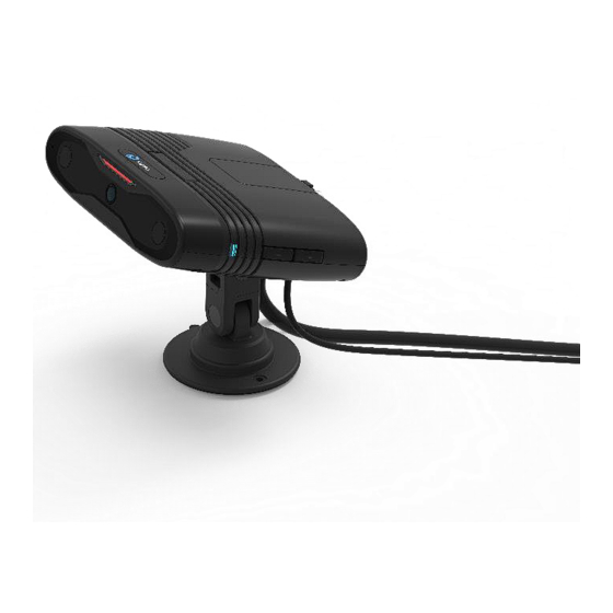
Cipia-FS10 Hardware and Interfaces 3.1. Cipia-FS10 Device Basics The Cipia-FS10 device is designed to be both functional and attractive. It is professional and robust and suits the vehicle environment. Figure 1: Cipia-FS10 Device ▪ Size – The dimensions of the product are (excluding mounting accessories) 120mm (L) x 95mm (W) x 30mm (T). - Page 7 IR LEDs. IR illumination is not visible to the driver. ▪ User Interfaces – The following mechanical interfaces exist for the MMI features. Figure 2: Cipia-FS10 Device Interfaces Cipia Vision Ltd. – Proprietary & Confidential Page 7 of 38...
- Page 8 Tricolor used to designate system status. Volume button Volume control. USB port Micro USB port for debugging servicing and data upload in case events and video footage cannot be uploaded wirelessly. Cipia Vision Ltd. – Proprietary & Confidential Page 8 of 38...
-
Page 9: System Building Blocks
3.2. System Building Blocks The following diagram depicts the Cipia-FS10 device’s main building blocks, interconnections, and interfaces. Figure 3: System Building Blocks Cipia Vision Ltd. – Proprietary & Confidential Page 9 of 38... -
Page 10: Hardware Specification
Micro SD card slot – up to 256GB, exFAT, SDHC/SDXC Watchdog • SW controlled – for application recovery • HW controlled – for system recovery Motion Sensor 3D Accelerometer / (±16g, 12bit, 100Hz or better) Linux v 4.14 Cipia Vision Ltd. – Proprietary & Confidential Page 10 of 38... - Page 11 Wi-Fi – 802.11 b/g/n/ac, • Frequency bands - 2.4G (B1-13) /5G (B36-165) • Dual mode support AP and/or Hotspot Wireless LAN Highest Max Power Output Band Frequency(MHz) (dBm) Power (dBm) FS-LTE-000/ADS only Cipia Vision Ltd. – Proprietary & Confidential Page 11 of 38...
- Page 12 1 x Input (0 – 32V). Digital or analog. GPIO • 1 x Open collector output. • 1 x I/O – Fully configurable by SW. Power Input Power • Direct vehicle battery connection (7-32V) Cipia Vision Ltd. – Proprietary & Confidential Page 12 of 38...
-
Page 13: Cable Pinouts And Requirements
▪ Interface – Internal. Pigtail style Table: Cable Pinouts Pin# Signal Remarks PWR_IN PWR_GND Black Purple RS232_TxD Green/Red RS232_RxD Yellow/Red COM_GND Green/Yellow GP_IN Green GP_OUT Blue GP_IO Grey Spare Red/Black Cipia Vision Ltd. – Proprietary & Confidential Page 13 of 38... -
Page 14: Environmental Standards
3.5. Environmental Standards The Cipia-FS10 device complies with the environmental standards detailed in the table below. Table: Environmental Standards Measure Descriptions Temperature Range Operating temp (boot/wakeup): -30°C to +70°C From battery: -20°C to +60°C Storage: -30°C to +80°C Humidity 95% ±5%RH @ +40°C, non-condensing... -
Page 15: Using Fleet-Sense
Using Fleet-Sense 4.1. Solution Architecture The following diagram depicts the various building blocks and optional interfaces of the Cipia-FS10 when integrated into a Telematics solution environment. Figure 5: Solution Architecture Diagram 4.2. Operation States and Modes The Cipia-FS10 application has three operational modes: 1. - Page 16 The following table defines the main attributes for each of these operational modes. The Cipia-FS10 device maintains two flags in its non-volatile memory to designate whether the device was ever professionally installed and whether it was calibrated. These flags are set/cleared according to the mode transition events described in the diagram below and can be queried by the server side as part of the device properties query (refer to the Cipia-FS10 Integration Manual).
- Page 17 OS/App/DMS library upgrades. Standard • Vehicle state and driver monitoring logic is active. • System operates according to config file settings. • Config file management from Server via defined protocols. Cipia Vision Ltd. – Proprietary & Confidential Page 17 of 38...
-
Page 18: Provisioning And Maintenance
4.3. Provisioning and Maintenance The features and capabilities of the Cipia-FS10 device typically used during the provisioning and maintenance phases of the device life cycle are described below. Config File Changes It is possible to alter the configuration file parameters, before or after installation using one of the following connection modes: ▪... - Page 19 See the Installation Manual for detailed description of the Cipia-FS10 installation and calibration process. Driver ID Enrollment There are a few options to add driver face information to the Cipia-FS10 device database: ▪ By sending a command from the mobile app to capture face attributes currently looking at the camera.
- Page 20 3. The FMS app retrieves the image and vector files to close the loop. When the FMS app enrolls an already enrolled driver, into other vehicles: 1. Per vehicle (Cipia-FS10 device), the middleware API is called with the Global ID number, vector file and permission status. This process is not necessarily done when the vehicle engine is running, and the device might therefore be unavailable for a period.
- Page 21 - they simply override the existing record with a new data set for the same Global Driver ID. The Cipia-FS10 main app checks if the Global Driver ID already exists in the driver DB, and if so, overrides it with the new data set.
- Page 22 Device Properties It is possible to send a device properties query to the Cipia-FS10 device through OTA (both server side and installer application) or via the USB connection. After it receives the query report, and after system boot, the Cipia-FS10 device reports its properties with the...
-
Page 23: Standard Mode
4.4. Standard Mode The following table lists all features and functions supported by the Cipia-FS10 device while in standard operation mode. Table: Standard Mode Functions Function Description Vehicle & driver The Cipia-FS10 device monitors all parameters and monitoring logic conditions as listed in the Events section of the configuration file and triggers events when conditions are met. - Page 24 GMT based on available clock sources like the cellular network and/or GPS. If neither of the two exist or are ‘up to date’, the Cipia- FS10 device manages accurate time (using the internal real-time clock) with a maximum deviation of 86 seconds per 24 hours (0.1%).
- Page 25 (and the cyclic video buffer) and commences a shutdown procedure that is completed in less than 20 seconds. The Cipia-FS10 device wakes up again once reconnected to a stable 7-32V power source. If there is no connection to the server at the time of the power loss, the event is stored in NVM and uploaded upon the next successful power-up.
- Page 26 Battery charge The internal Li-Ion battery charging is managed by the management Cipia-FS10 main application or a parallel service managed by the OS according to known charging best practices for Li-Ion batteries (temperature, aging, usage profile) to achieve longest possible effective lifetime without compromising the ability of the battery to power the device for at least one minute upon power loss.
-
Page 27: Cipia-Fs10 Events
Cipia-FS10 Events The following table describes the various event types which can be detected and reported to the backend application by the Cipia-FS10 device as a function of the vehicle status (ignitions switch/speed/heading angle change), external triggers, driver behavior or system status changes. - Page 28 ▪ Location time – Upon event detection by the DMS algorithm, the Cipia- FS10 App fetches the “last location time” and associates it with the generated event. If the location time is different from the event time, it means that the event location/speed/heading are not necessarily accurate.
- Page 29 ▪ Whether the event is enabled or disabled. ▪ The data sets which should be sent to the server upon event generation (data/image/footage). ▪ The user feedback patterns activated on event detection. Cipia Vision Ltd. – Proprietary & Confidential Page 29 of 38...
-
Page 30: Configuration Settings
4.7. Telematics GPIO Signaling It is possible to define (in the config file) that one of the digital inputs of the Cipia-FS10 device be used by the T-Box whenever a driver behavior event is detected by the Telematics box. On activation of this input, the Cipia-FS10 device triggers an event and captures an image or video footage as defined in the config file (with pre- and post- buffers). -
Page 31: Bluetooth
The RS232 link is used by the Cipia-FS10 device to transmit event data or snapshots to the server-side. The RS232 link should not be used to transfer video footage unless the data packet size is lower than the maximum defined by the Telematics box datasheet. - Page 32 Another use of the Wi-Fi interface is for video streaming to the Cipia-FS10 mobile app for installation, calibration and debugging purposes. In this scenario, the mobile app connects to the Cipia-FS10 device’s access point. While in Installation and Calibration mode, the Wi-Fi network is turned on by the Cipia- FS10 app and accept connection attempts with the correct PIN and sign-in procedure.
-
Page 33: Cipia-Fs10 Hmi
Cipia-FS10 HMI The following table describe the audible and visual feedback provided by the Cipia-FS10 system LED and its speaker in various states of system operation. Table: Audible & Visual Feedback Event/State System LED Sound Speech Power-up (S) √ ×... - Page 34 Maintenance System mode Calibration System mode Calibration error Button System pressed (Confirmation Driver Driver identified Unidentified Driver Yes – driver Configuratio Driver image Driver Yes – loss Configuratio Cipia Vision Ltd. – Proprietary & Confidential Page 34 of 38...
- Page 35 ▪ If sound effects and voice messages are both active in the configuration file, the message is played right after the sound effect. ▪ All voice messages are only played once. LED and sound effects may be repeated. Cipia Vision Ltd. – Proprietary & Confidential Page 35 of 38...
-
Page 36: Test And Evaluation Kit
Test and Evaluation Kit You can use the Cipia-FS10 Evaluation Kit (EVK) with a test server provided by Cipia (Middleware Server and basic cloud), to test the Cipia-FS10 device behavior, features and functions, without having to professionally install the device or to develop a single line of code. -
Page 37: Standards And Regulations Notices
The device has also been evaluated and shown compliant with the IC RF Exposure limits under mobile exposure conditions (antennas at least 20cm from a person’s body). Cipia Vision Ltd. – Proprietary & Confidential Page 37 of 38... -
Page 38: Red
Hereby, Cipia Vision Ltd. declares that the radio equipment type is in compliance with Directive 2014/53/EU. The full text of the EU declaration of conformity is available at the following internet address: https://cipia.com Notice: The device complies with RF specifications when the device used at least 20cm from human body.
Need help?
Do you have a question about the CIPIA-FS10 and is the answer not in the manual?
Questions and answers