Table of Contents
Advertisement
The CLD 780 TR may only be switched on when it is connected to a vacuum pump and adequate
vacuum is achieved. In addition the vacuum tubing from the analyzer to the pump must be abso-
lutely light-tight and of adequate diameter (at least 16 mm). Ideally, the vacuum pump is switched
on, with dry air cartridges connected, 1 hour before the instrument itself and, after use, left running
30 – 60 minutes after the CLD 780 TR is switched off.
Similarly, it is extremely important that:
– the dry air inlet is always connected to an indicating dryer cartridge with unused drying capacity
(also, if possible, when the instrument is switched off).
– the O
inlet is always connected to an adequate source of dry oxygen (at 750 to 1100 mbar
2
abs) or dry air (at atmospheric pressure).
– the sample is passed through a particle filter (pore size 5 µm or less).
When bringing the CLD 780 TR into operation for the first time, or after an extended shut-down with
the vacuum pump and/or dryer cartridges removed, run the vacuum pump, with dry air cartridges
connected, for several hours before switching the instrument on.
If these precautions are not observed then the consequences may be destruc-
tion or damage to the photomultiplier tube through exposure to daylight, or by
the formation of condensation.
WARNING
Advertisement
Table of Contents

Summary of Contents for Eco Physics CLD 780 TR
- Page 1 WARNING The CLD 780 TR may only be switched on when it is connected to a vacuum pump and adequate vacuum is achieved. In addition the vacuum tubing from the analyzer to the pump must be abso- lutely light-tight and of adequate diameter (at least 16 mm). Ideally, the vacuum pump is switched on, with dry air cartridges connected, 1 hour before the instrument itself and, after use, left running 30 –...
-
Page 2: Table Of Contents
3.1 Measurement principle 14 PRINCIPLE 3.2 Description of the CLD 780 TR analyzer INSTALLATION 4.1 Unpacking 4.2 Installing the CLD 780 TR and its peripherals OPERATING GUIDE 5.1 Start up 5.2 Operating the analyzer 35 5.3 Shutting the system down79 CALIBRATION 6.1 Introduction... - Page 3 9.5 Cleaning the instrument 131 TROUBLESHOOTING 10.1 Error messages and correction procedure 10.2 Electrical test points DISPOSAL QC/CONFORMITY GAS PHASE TITRATION OPTIONS CONTINUOUS MEASURE MODE Read the safety rules first! (Section 1.2) CLD 780 TR / July 2000...
- Page 4 1.2.1 Definitions, Personnel, Definitions of terms 1.2.2 Symbols and safety hints used in this manual 1.2.3 Intended use of the analyzer 1.2.4 General dangers 1.2.5 General safety rules 1.2.6 Responsibilities and duties of the supplier CLD 780 TR / July 2000...
- Page 5 (e.g. OH radicals, and a large number of hydrocarbons) which can produce errors of several ppb. The design of the CLD 780 TR is based to a large extent on the proven “fore-chamber” principle used by its predecessor in- strument, the now legendary ECO PHYSICS CLD 770 AL ppt.
-
Page 6: Introduction
Introduction 1.2 Safety precautions This section summarizes the safety precautions, which are to be observed without exception when using the CLD 780 TR analyzer (in the following sections called “analyzer“). For all persons working with the analyzer, reading and comprehending the sections relevant to their work is obligatory. - Page 7 Warning labels on the back panel (outside): – Servicing to be performed by qualified personnel only. Disconnect power before undertaking repair or maintenance Servicearbeiten dürfen nur durch qualifiziertes Personal durchgeführt werden. Netzstecker ziehen vor Reparaturen oder Instandstellungsar- beiten. CLD 780 TR / July 2000...
- Page 8 – Pressurized gas cylinders must be secured against falling. Horizontally stored cylinders must be prevented from rolling. – The pressure reduction valves and all tubing from gas cylinder to vent must be regularly checked for leaktightness. – etc. WARNING Toxic gases! CLD 780 TR / July 2000...
- Page 9 As an example (relating to the sampling system) special care should be observed when handling hot and aggressive gases, and the appropriate safety precautions applied. CLD 780 TR / July 2000...
- Page 10 Accessories and spare parts For maintenance and repair the options and spare parts originally manu- factured by ECO PHYSICS and included in this manual should be used exclusively. Modifications and alterations...
- Page 11 Duty to observe and inform In case of any (remaining) risks or dangers, which have not been covered in this manual, the end user of the analyzer is requested to inform the supplier immediately. CLD 780 TR / July 2000...
-
Page 12: Specifications
E C O P H Y S I C S Specifications Read the safety rules first! (Section 1.2) 2.1 CLD 780 TR Performance data (O operation) 2.2 CLD 780 TR Operating data 2.3 Dimensions and weight of the CLD 780 TR CLD 780 TR / July 2000... - Page 13 E C O P H Y S I C S Specifications 2.1 CLD 780 TR Performance data (O operation) Measurement range 0.005 - 5 ppb 0.01 - 10 ppb 0.05 - 50 ppb 0.1 - 100 ppb 0.5 - 500 ppb In each range the signal integration in- terval can be varied in 0.1 sec steps...
- Page 14 E C O P H Y S I C S Specifications 2.2 CLD 780 TR Operating data Analog outputs 0 to 1 V (galvanically isolated) 0.2 to 1 V 0 to 10 V (into 500 kΩ min) 2 to 10 V 0 to 20 mA (into 500 Ω...
- Page 15 E C O P H Y S I C S Specifications 2.3 Dimensions and weight of the CLD 780 TR Dimensions – Housing width 440 mm height 255 mm depth 420 mm – Front panel width 483 mm height 264 mm...
-
Page 16: Measurement 3.1 Measurement Principle
Read the safety rules first! (Section 1.2) 3.1 Measurement principle 3.2 Description of the CLD 780 TR analyzer 3.2.1 Introduction 3.2.2 Detector unit 3.2.3 Ozone generator 3.2.4 Gas flow 3.2.5 CLD 780 TR Electronics CLD 780 TR / July 2000... - Page 17 NO concentration. The interference signal S can be very simply determined by use of a pre-chamber. This is possible because most of the interference reactions that produce the signal S are signifi- cantly slower than reactions [1] to [3]. CLD 780 TR / July 2000...
- Page 18 E C O P H Y S I C S Measurement principle For this reason the CLD 780 TR employs a pre-chamber where NO com- pletely reacts with ozone. If the residence time of the sample gas in the pre-chamber allows the complete deactivation of the excited NO...
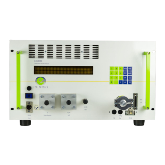
- Page 19 3.2 Description of the CLD 780 TR analyzer 3.2.1 Introduction Great effort has been made during the design phase of the CLD 780 TR to achieve a modular construction. A further characteristic of the instrument, essential for airborne installations, is the location of all external connec- tion points (both electrical and pneumatic) on the front panel.
- Page 20 ) instead of dry air. The analyzer is optimized for operating under this condition (see 4.2.3, pt. 3). The basic version of the CLD 780 TR does not include an internal pressure regulator for the ozone generator oxygen supply. This option is however recommended for optimal performance (see section 3.3 in Appendix 4).
- Page 21 13 Pressure sensor board 14 Photomultiplier (PMT) 15 Cooler 16 Cooler control electronics 17 Ventilation duct 18 Fans 19 High-voltage/pre-amp mod- 20 Power supply board (PONOX TR) 21 Control board (LONOX) 22 Interface board 23 Alphanumeric display CLD 780 TR / July 2000...
- Page 22 E C O P H Y S I C S Measurement principle 3.2.4 Gas flow (see Fig. 3.2 “CLD 780 TR Gas Flow Diagram“) A powerful, external vacuum pump (B) generates a reaction chamber vacuum of approx. 14 mbar. It also serves to draw sample gas and ozone generator supply oxygen into the analyzer.
- Page 23 The flushing air is vented into to the main vacuum line between the pres- sure sensor [13] and the main-chamber vacuum connection points. This ar- rangement protects the pressure sensor from damage by ozone. CLD 780 TR / July 2000...
- Page 24 E C O P H Y S I C S Measurement principle Fig. 3.2 “ CLD 780 TR Gas Flow Diagram“ Ozone scrubber Vacuum pump Sample inlet Sample flow restrictor inlet with filter Ozone flow restrictor Ozone generators Solenoid valve...
- Page 25 3.2.5 CLD 780 TR Electronics The following is a description of the electronic modules in the instrument, and their functions. Refer to the CLD 780 TR block diagram (Fig 3.3). The numbers in parentheses refer the components so labeled in the block dia- gram.
- Page 26 Furthermore the instrument has one digital, optically isolated input and two such outputs for possible process control purposes [15]. Additional in- formation about digital and analog outputs are listed in chapter 2 “Speci- fications“. CLD 780 TR / July 2000...
- Page 27 3 Control board (LONOX) 9 Pulse-shaper board 15 PLC interface 4 Cooler (PPTFE) 16 Socket for digital & ana- 5 Temperature sensor 10 Interface board (IFNOX) log I/O (DB25) 6 Reactor inlet heating 11 Keypad CLD 780 TR / July 2000...
-
Page 28: Installation
E C O P H Y S I C S Installation Read the safety rules first! (Section 1.2) 4.1 Unpacking 4.2 Installing the CLD 780 TR and its peripherals 4.2.1 Location 4.2.2 Fitting instructions for Swagelok connectors 4.2.3 Installing the gas tubing... -
Page 29: Unpacking
– 3 silica gel drying columns [F], for the oxygen and dry air supplies – 2 connecting tubes (from silica gel cartridge to CLD 780 TR [4], [6], Ø 10 x 6 mm x 1.5 m, PVC, with 1/4” steel tube fitting –... -
Page 30: Installing The Cld 780 Tr And Its Peripherals
2. Make a further 1/4 turn max with a wrench to tighten (1/8” size tube fittings only 1/8 turn). Note: All tubing supplied by ECO PHYSICS as part of an instrument delivery will have the Swagelok fittings already fitted. Install as per paragraph b) above. - Page 31 E C O P H Y S I C S Installation Fig. 4.1 ”Swagelok tube fittings“ Tube Front ferrule Back ferrule CLD 780 TR / July 2000...
- Page 32 E C O P H Y S I C S Installation 4.2.3 Installing the gas tubing between the CLD 780 TR and its peripherals (see Fig. 4.2). Attention: The following notes apply to the standard CLD 780 TR in- strument. Before installing an analyzer fitted with options, please read Appendix A4.
- Page 33 Important: The vacuum connector and the tubing to the vacuum pump must be totally opaque. If light enters the instrument through the vac- uum inlet the measured values will be incorrect and in the worst case the photomultiplier may suffer damage. CLD 780 TR / July 2000...
- Page 34 E C O P H Y S I C S Installation 4.2.4 Connecting the CLD 780 TR power and control cables (see Fig. 4.2). 1. The operator is responsible for the correct supply of power to the in- strument. Connect the power cable supplied [12] to an external 28 VDC power supply [G] and plug the cable connector into the socket [11] on the analyzer front panel marked “28 VDC Power”.
- Page 35 15 RS 232 D-connector 29 Power cable (O scrub- 4 Tubing from silica gel 16 RS 232 interface cable ber to vac. pump) cartridge to dry air inlet 17 O cylinder CLD 780 TR / July 2000...
-
Page 36: Operating Guide
5.2.2 Description of the display windows of the CLD 780 TR 5.3 Shutting the system down 5.3.1 Shutting the system down for an extended period 5.3.2 Shutting the system down for a short period CLD 780 TR / July 2000... - Page 37 The vacuum pump will switch on automatically when the ozone scrub- ber reaches the set temperature. 2. Turn power switch of the CLD 780 TR analyzer to “ON“. The analyzer identification window appears for about 4 secs and immediately af- terward the “MEAS”...
-
Page 38: Operating The Analyzer
E C O P H Y S I C S Operating Guide 5.2 Operating the analyzer 5.2.1 Introduction The CLD 780 TR has a keypad with 20 keys: The following 6 non-numeric keys: – MEAS – MENU – RANGE – CAL –... - Page 39 E C O P H Y S I C S Operating Guide User-entered values and calibration data are stored by battery-buffered RAM even during extended power-down periods. The CE key (“Clear Entry“) serves to erase erroneous entries. CLD 780 TR / July 2000...
- Page 40 Measure window (activated with MEAS key) * The numbers in brackets in the following section refer to the software window numbers in the diagram “CLD 780 TR window structure“ at the end of section 5.2, Figs. 5.1 to 5.4. – The concentrations of NO and NO.c measured in the sample gas in ppb are displayed below the appropriate labels.
- Page 41 – “PWUP“, “O3UP“ and “DOWN“ appear when appropriate, as also error and warning codes, as described in window (1). The analytical basis of the “Continuous measuring mode“ is described in detail in Appendix A5. CLD 780 TR / July 2000...
- Page 42 762 photolytic converter is used together with the CLD 780 TR then two more modes are applicable - “NO.c“ and “NO.c (cont)“. The alternate measurement of NO and NO.c with a PLC 762 and a single CLD 780 TR is also possible (although not recommended by ECO PHYSICS) and the analyzer software does allow this sequential measurement to be made, in which case two more modes are applicable - “NO and NO.c“...
- Page 43 NO interferences. – “NO.c“: The sample gas is passed through a PLC 762 photolytic con- verter before entering the CLD 780 TR analyzer. Only NO.c is meas- ured and displayed. NO.c is the raw value of the sample gas NO...
- Page 44 Operating Guide – “NO.c (cont.)“: The sample gas is passed through a PLC 762 photo- lytic converter before entering the CLD 780 TR analyzer. Only NO.c is measured and displayed. NO.c is the raw value of the sample gas concentration after passing through the converter and consists of the sum of the NO and NO signals.
- Page 45 Press the “MEAS“ key to move to the “MEAS“-window (1)). Caution: It is important when choosing a mode to confirm the selection by en- tering “YES“ before leaving this window. Otherwise the previously used mode will remain selected. CLD 780 TR / July 2000...
- Page 46 AICA may be set to 0 secs and SR must be at least 1000 ms. The interval between automatic λ determinations is set in window (7), “AICI-Time“. This must be greater than T AICA CLD 780 TR / July 2000...
- Page 47 1 to 120 secs. The width should be set to a multiple of the AIC interval, T , since new data is available only once per interval. AICI Press MEAS or MENU to exit this level. CLD 780 TR / July 2000...
- Page 48 Note: With filter widths up to 179 sec the raw data is read into the filter every 100 ms. With longer filter windows, the raw data is first averaged over 1 sec, then this value is fed to the slide filter. This reduces the memory requirement. CLD 780 TR / July 2000...
- Page 49 If the units are changed, then the new measurement values may very well lie outside of the recorder settings, since kcps and ppb val- ues are not directly interchangeable. Press MEAS or MENU to exit this level. CLD 780 TR / July 2000...
- Page 50 Entry of date and clock time 1. “System Date“: Entry of date (dd-mm-yy) e.g. for October 13, 1988 enter 13-10-88 2. “Time“: Entry of the clock time (in hrs and min) To exit select “MEAS“ or “MENU“. CLD 780 TR / July 2000...
- Page 51 0 to 4000 hrs. (see W-02, chapter 10). 2. “Mains“: A “Count-Up“ hour counter shows the operating hours of the analyzer to date. To exit select “MEAS“ or “MENU“ CLD 780 TR / July 2000...
- Page 52 PMT tube. 3. “Delay“: Set the purge times for each valve from this window: a) “Rea“: CLD 780 TR solenoid valve (see Fig. 3.1, pos. 6) b) “Cal.“: Solenoid valve (sample/cal. gas) in PLC 762 c) “Cnv.“: Solenoid valve (NO/NO.c) in PLC 762...
- Page 53 2. “Int [s]“: The integration time can be selected from 0.1 to 999.0 sec. The displayed values are nevertheless shown in counts/sec., e.g. 10 sec. are chosen for an integration time; the total counts over 10 sec. is always divided by 10 sec. to express counts/sec. CLD 780 TR / July 2000...
- Page 54 Caution: Any settings made in this window are valid only so long as the instrument remains in the “TEST“ mode, and will be deactivated on returning to the MEAS function, when the prior settings will become valid again. Return with “MEAS“ or “TEST“. CLD 780 TR / July 2000...
- Page 55 Note: In normal operation, should be 5 - 10 °C, depending on room tem- perature. If -18 °C is displayed, this indicates that the CLD 780 TR is not receiving data from the PLC 762. Check power to PLC and that the PLC/TR cable is fitted correctly.
- Page 56 Activate with the “RANGE“ key. “RNGE“ is shown in upper right hand corner of the display . 1. “Range“: The CLD 780 TR analyzer is designed in such a way that the choice of measurement range has no effect on the detection limit. The sensitivity is the same for all available ranges and is solely dependent on the integration interval.
- Page 57 “SYS“ key. The analyzer automatically enters this mode following certain fault conditions. 1. “Stand-by“: The CLD 780 TR is forced into a “holding“ mode. In this mode the ozone generators are turned off, but operating temperature of the different components are maintained (see paragraph 5.3.2).
- Page 58 After rectifying the error and pushing the “MEAS“ key the message will disappear and measurement will resume. The short “O3UP“ and “PWUP“ phases precede the normal measuring mode “MEAS“. Return with “MEAS“. CLD 780 TR / July 2000...
- Page 59 Master Reset, the bypass regulator loop is disenabled. Once a non- zero value has been entered, the bypass regulator loop cannot be disabled unless a Master Reset is carried out, although the set value may be changed if necessary. CLD 780 TR / July 2000...
- Page 60 – With key NO: return to window (28) After a “Master Reset“ is performed the Error Code E-01 “Setup and Cal Data Lost“ appears. To remove this error, perform the warm start proce- dure by pressing “SYS“, “YES“ and “MEAS“. CLD 780 TR / July 2000...
- Page 61 5.2.2.7 Calibration of the CLD 780 TR and PLC 762 Depending on the measurement mode selected in window (3), the user will be prompted to perform a calibration of the CLD 780 TR or of the PLC 762. – If one of the following is selected under “Measurement Mode“: –...
- Page 62 E C O P H Y S I C S Operating Guide 5.2.2.7.1 Calibration of the CLD 780 TR analyzer with NO and/or zero air (30) “NO-Ref“-window This window allows the user to enter the NO calibration gas reference value and set the measurement range. (In all windows under the calibra- tion procedure, “CAL“...
- Page 63 – “YES“ key: Zero gas reference point measurement will be executed. Window (33) appears. – “NO“ key: Zero gas reference point measurement will be by-passed and the NO calibration will start directly. Window (35) appears. CLD 780 TR / July 2000...
- Page 64 762? “Zero-Air“ must be connected to the “NOx Cal“-inlet if no exter- nal unit controls the solenoid valve “NOx Cal/Zero-Air“. This valve is not controlled by the CLD 780 TR. – If a calibrator is used, has it been purged sufficiently? –...
- Page 65 NO-calibration made. The previous cycles ensure that the system is adequately purged to produce stable measuring conditions. The lower line of the display shows the cycle number (blinking value) and integration interval (“P“ or “M“ for pre and main chamber measurement respectively). CLD 780 TR / July 2000...
- Page 66 If the value is acceptable, press the “YES“ key. The new calibration fac- tors will now replace the old ones, and the “Copy?“-window (38) ap- pears. CLD 780 TR / July 2000...
- Page 67 [Y/N]“: – With “YES“ or “MEAS“ the calibration procedure is aborted and the analyzer returns to measuring mode. – With “NO“ the system returns to the beginning of the calibration pro- cedure, window (30). CLD 780 TR / July 2000...
- Page 68 Agency, a US government organization) designated procedures. See also chapter 6 and Appendix 3. (41) “Select Instrument“-window Option to select which instrument is to be calibrated - the CLD 780 TR or PLC 762 . Note: All windows involved in the photolytic converter calibration proce- dures are indicated with PLCCAL.
- Page 69 Note: This procedure can be aborted at any time with “MEAS“. The “Exit“-window (48) appears, and by pressing NO the start of the calibra- tion can be reached (window (42)). CLD 780 TR / July 2000...
- Page 70 Caution: In the absence of sufficiently stable calibration gas, GPT is not possible. Window (45) remains active to indicate this (“Cal. gas supply or calibrator needs to be checked“). If the values are stable, the analyzer automatically registers the values and window (46) appears. CLD 780 TR / July 2000...
- Page 71 Window (1) ap- pears. With “NO“: The new value for WK is rejected and the old value remains valid. The initial window of the PLC 762 calibration procedure appears (window (42)). CLD 780 TR / July 2000...
- Page 72 “Zero Calibration (Y/N)“: Certified, or extremely good quality zero air is necessary for this calibration step. Press “YES“ to proceed with the zero point determination. Window (52) appears. Press “NO“ to proceed directly to the NO calibration step. Window (54) appears. CLD 780 TR / July 2000...
- Page 73 PLC 762? Zero air must be connected to the “NO Cal“-inlet if no external unit controls the solenoid valve “NO Cal/Zero-Air“. This valve is not controlled by the CLD 780 TR. – If a calibrator is used, has it been purged sufficiently? –...
- Page 74 Values from 1 to 600 ppb are accepted. Press “YES“ to confirm the entered value. Window (56) appears. Press “MEAS“ to abort the calibration and return to measure (window 1a). CLD 780 TR / July 2000...
- Page 75 Prompts the operator to check the NO-calibration gas supply. – Is calibration gas being supplied at atmospheric pressure to the NO Cal gas inlet of the photolytic converter or to the CLD 780 TR sample inlet? – If using a gas calibrator, has it been adequately purged? –...
- Page 76 Automatic Interference Correction calculation will not give accurate values for the interval up to the first AIC determination. Press “NO“ to reach the “Enter Value!“ window (59). Press “YES“ and “MEAS“ to return to measure mode. CLD 780 TR / July 2000...
- Page 77 – Press “YES“ to abort calibration and return to measuring mode. The previous calibration factors remain valid. Window (1a) appears. – Press “NO“ to return to the start of the calibration procedure, window (51). CLD 780 TR / July 2000...
- Page 78 E C O P H Y S I C S Operating Guide Fig. 5.1 Software window structure CLD 780 TR / July 2000...
- Page 79 E C O P H Y S I C S Operating Guide Fig. 5.2 Software window structure (cont.) CLD 780 TR / July 2000...
- Page 80 E C O P H Y S I C S Operating Guide Fig. 5.3 Software window structure (cont.) CLD 780 TR / July 2000...
- Page 81 E C O P H Y S I C S Operating Guide Fig. 5.4 Software window structure (cont.) CLD 780 TR / July 2000...
-
Page 82: Shutting The System Down79
Before opening the connection between the analyzer and the vacuum pump or the line between dry air inlet and silica gel cartridge switch off the CLD 780 TR and let run the vacuum pump for at least one hour. Otherwise damp air might condense, freeze and destroy the photo- multiplier (PMT). - Page 83 E C O P H Y S I C S Operating Guide CLD 780 TR / July 2000...
-
Page 84: Calibration
(Section 1.2) 6.1 Introduction 6.2 Performing a calibration 6.2.1 Calibration using a gas diluter 6.2.2 Single point calibration (”Span Check“) 6.2.3 Multi point calibration (checking) 6.2.4 Checking the conversion efficiency (W ) of the converter CLD 780 TR / July 2000... -
Page 85: Introduction
W <96 % in order to prevent an excessive dependability on correction factors. If the CLD 780 TR is used, combined with the PLC 762 photolytic con- verter, a totally new aproach is possible: The analyzer can automatically determine W (see also section 5.2.2.7.2... - Page 86 24 hours or more frequently. A multi-point calibration should be done pe- riodically e.g. after every maintenance check. Remark: ECO PHYSICS offers an integrated system called JETNOX, one example of which was installed in a Boeing 747 passenger/cargo air- craft, automatically measuring stratospheric air quality for 12 months as part of the Swiss NOXAR project.
- Page 87 – Toggle with ”NO“ to the desired range and confirm the selection with ”YES“ – The cursor is now underneath the field for the integration time inter- val. Enter Integration time (0.1 - 600 sec.) and confirm with ”YES“. – Return with ”MEAS“. CLD 780 TR / July 2000...
- Page 88 “ mode, ”Select Instrument“ will appear on the display after pushing the ”CAL“ key. In this case ”CLD 780 TR“ has to be chosen. After that the calibration follows the same procedure as described in 5.2.2.7.1. 5. Copying of calibration value into other ranges: After accepting the calibration the ”Copy Cal“-window appears.
- Page 89 7. If required, and if a PLC 762 is being used in combination with the a- nalyzer, then the NO.c channel may also be checked for linearity. In this case, in Step 1 above choose NO.c in the submenu ”Mode“ instead of NO. The repeat steps 2 to 6. CLD 780 TR / July 2000...
- Page 90 – It is recommended that the GPT is done in the same range as is to be u- sed for measurement. – NO(1) and NO.c(1) mean: NO and NO.c concentrations before ad- ding ozone (O – NO(2) and NO.c(2) mean: NO and NO.c concentrations after adding ozone (O CLD 780 TR / July 2000...
- Page 91 NO channel and hence the NO impurity content is always measured as well. – NO(2) should be 10 - 50% of NO(1) Caution: If the converter efficiency is <50 %, the PLC 762 xenon lamp needs to be replaced. CLD 780 TR / July 2000...
- Page 92 E C O P H Y S I C S Calibration Fig. 6.1 ”Connection drawing for calibra- tion of a CLD 780 TR“ The information given in brackets applies if the CLD has been orde- red without the PLC 762.
- Page 93 E C O P H Y S I C S Calibration CLD 780 TR / July 2000...
-
Page 94: Practical Hints
First read the safety regulations! (Section 1.2) 7.1 Sampling 7.2 Quenching 7.3 Interferences 7.4 Observing the raw signal 7.4.1 Stability of the calibration 7.4.2 Checking the optical system 7.5 Influence of atmospheric pressure fluctuations on the measuring signal CLD 780 TR / July 2000... -
Page 95: Sampling
To avoid calibration gas in the vicinity of the sampling point affecting sub- sequent measurements, it is advisable to pass the bleed flow through an activated charcoal filter. The created pressure drop due to the filter must, however, be insignificant (<1 mbar). CLD 780 TR / July 2000... -
Page 96: Quenching
This phenomena can be corrected by either applying a compensation fac- tor to the measurement data (if the humidity is known) or by the controlled humidification of the carrier gas (diluent gas) during calibration. CLD 780 TR / July 2000... -
Page 97: Interferences
Their effect does become significant du- ring the measurement of very low (ppt level) concentrations of NO. The CLD 780 TR analyzer eliminates more than 90 % of the signal inc- rease due to this effect through the use of an integrated pre-chamber (see Chap. -
Page 98: Observing The Raw Signal95
Practical hints 7.4 Observing the raw signal The CLD 780 TR allows easy access to the raw signal in counts, making it possible for the operator to view information about the calibration gas stability, the condition of the optical system and the gas flow path in the analyzer. - Page 99 PLC 762 (if appropriate) must be checked and if necessary cleaned. Especially sensitive to contamination are the flow restrictors: Flow restrictors in the CLD 780 TR: (see Fig. 3.1 & 3.2) – Ozone generator outlet (4) – PMT housing flush outlet (11) –...
-
Page 100: Influence Of Atmospheric Pressure Fluctuations On The Measuring Signal
For application where the ambient pressure varies rapidly (i.e. in airborne platforms), it is recommended that a CLD 780 TR fitted with Option 2 (By- pass system) be used. CLD 780 TR / July 2000... - Page 101 E C O P H Y S I C S Practical hints CLD 780 TR / July 2000...
- Page 102 Read the safety rules first! (Section 1.2) 8.1 Introduction 8.2 Interface hardware 8.2.1 Interface specification 8.2.2 Connector pinout 8.2.3 Computer cable 8.3 Communications protocol 103 8.3.1 Control signals 8.3.2 Communications protocol 8.3.3 Examples 8.4 Command set CLD 780 TR / July 2000...
-
Page 103: Introduction
Please note that the information in this section relates to specialist pro- gramming, communications and electronics functions and is highly specific to the CLD 780 TR system. The information given is not meant to be a tuto- rial and is intended for use by experienced professionals only. -
Page 104: Interface Hardware
RS-232 5 GND signal ground RS-232/485 6 RD1 / TD1 receive/transmit 1 bi-directional RS-232 7 RTS request to send output RS-232 8 CTS clear to send input RS-232 9 N.C. not connected RS-232 Screen CLD 780 TR / July 2000... - Page 105 RxD 2 >..........< TxD 3 TxD 3 >..........< RxD 2 GND 5 >..........< GND 5 RTS 7 >..........< CTS 8 CTS 8 >..........< RTS 7 Screen I ..........I Screen CLD 780 TR / July 2000...
-
Page 106: Communications Protocol
The master sends a command telegram, the slave acknowledges the com- mand with an answer telegram. 8.3.1 Control signals No signal handshake is supported by the CLD 780 TR. Thus a host com- puter must be fast enough to handle the CLD 780 TR data stream. 8.3.2 Communications protocol... - Page 107 CLD 780 TR → Computer Response to a valid command Error code Response to valid data request commands Error code Data Data Data Block check code Response to a corrupted message (see Error code definitions) Error code CLD 780 TR / July 2000...
- Page 108 <STX> “0“ “3“ “S“ “A“ “1“ “ ,“ “1“ “ ,“ “0“ <ETX> <BCC> Error code definitions The CLD 780 TR will respond to the host with an “NAK“ message if any of the following conditions occur: Block check error: The received BCC did not correspond to the received data.
- Page 109 The BCC is generated by XOR-ing every message byte over the message block - including STX and ETX. The resulting character is transmitted at the end of the message. Only the lowest 7 bits are relevant. CLD 780 TR / July 2000...
- Page 110 ACK, Error code, STX,...Data..., ETX, BCC b) Transmission errors The host sends a command to the CLD 780 TR which receives the message corrupted and responds with a negative acknowledge. The host repeats the message. The second trial is successful.
-
Page 111: Command Set
2 = measure NO + NO.c 3 = “Remote measure” mode → “Test” commands are available. CONFUSE WITH “REMOTE” MODE!) 4 = measure NO (cont.) → “Cont.Meas” 5 = measure NO.c (cont.) → “Cont.Meas” CLD 780 TR / July 2000... - Page 112 [s] (0 = off) 000 ... 255 Rea. Delay: xxxx [ms] 0020 ... 9999 Leave current measurement cycle 4,12*) Start measurement cycle 2,4,12*) Note: Each measurement cycle must be initiated (i.e. syn- chronized) using the HS command. CLD 780 TR / July 2000...
- Page 113 Copy calibration coefficients 1,2,4*) Source measurement range [0 ... 4] – comp. SR Target measurement range [0 ... 4] – comp. SR Enter calibration slide filter time constant 2,4*) xxx: 001 ... 120 [s] CLD 780 TR / July 2000...
- Page 114 0 = off 1 = on Switch valve 0 = sample 1 = cal Photolysis converter valve 4,5*) 0 = NO 1 = NO.c Select reaction chamber 4,5*) 1 = pre-chmber 2 = main chamber CLD 780 TR / July 2000...
- Page 115 = Measurement value in ppb (floating point) 1 = cps Reply: i,xxxxxx,yyyyyy xxxxxx = Pre-chamber measured value in cps during calibration and AIC (in Cont. Meas ******) yyyyyy = Main chamber measured value in cps CLD 780 TR / July 2000...
- Page 116 = Measurement value in ppb (floating point) 1 = cps Reply: i,xxxxxx,yyyyyy xxxxxx = Pre-chamber measured value in cps during calibration and AIC (in Cont. Meas ******) yyyyyy = Main chamber measured value in cps CLD 780 TR / July 2000...
- Page 117 3 = Photolysis converter temperature Reply: ± xxx [°C] Report pressure 0 = Reaction chamber pressure 1 = Bypass pressure (fine) 2 = Bypass pressure (coarse) 3 = Ozone generator inlet pressure Reply: xxxx [mbar] CLD 780 TR / July 2000...
- Page 118 Analyzer type and EPROM version Reply: V x.y TR Return date and time Reply: yy,mm,dd,hh,mm (year, month, day, hour, minute) Operating hours 1 = Vacuum pump (”Count-down“ hours) 2 = Analyzer (”Count-up“ hours) Reply: hhhhhh [h] CLD 780 TR / July 2000...
- Page 119 Only accepted in “NO (cont.)” measuring mode (see SM command) 11*) Only accepted in “NO.c (cont.)” measuring mode (see SM command) 12*) Not available in “NO (cont.)” or “NO.c (cont.)” measuring modes (see SM command) CLD 780 TR / July 2000...
-
Page 120: Periodic Maintenance
120 9.3 Silica gel drying cartridges 9.4 Cleaning the analyzer reaction chambers 9.4.1 Disassembling and cleaning the pre-chamber 9.4.2 Removing and cleaning the main chamber and red filter 9.5 Cleaning the instrument CLD 780 TR / July 2000... - Page 121 Before opening the connection between the analyzer and the vacuum pump or the line between dry air inlet and silica gel cartridge switch off the CLD 780 TR and let run the vacuum pump for at least one hour. Otherwise damp air might condense, freeze and destroy the photo- multiplier (PMT).
-
Page 122: Filtering The Sample Gas
(which may cause damage and/or leaks), the flow restrictors (which may become ob- structed) or the main reaction chamber (which will cause erroneous meas- ured values). CLD 780 TR / July 2000... -
Page 123: Dry Air And O Inlet Filter
The dry air filter is mounted at the dry air inlet on the front panel of the CLD 780 TR (see Fig. 4.2, (3)). The filter assembly is shown in Fig. 9.1. At the oxygen inlet a second identical dry air filter (see Fig. 4.2, (5) is in- stalled. - Page 124 “Dry air filter, O inlet filter” Gas inlet Front panel 4 Hex socket screws Filter housing lid Glass-fibre pre-filter (φ 32 O ring Main filter (PTFE membrane 1 µm, φ 37 mm) Filter housing base CLD 780 TR / July 2000...
-
Page 125: Silica Gel Drying Cartridges
4. Exchanging the silica gel cartridge: note that the connecting tubing to the analyzer is connected to the cartridge outlet (outlet: bottom of car- tridge; inlet: on the lid side). 5. Turn pump back on. CLD 780 TR / July 2000... - Page 126 E C O P H Y S I C S Periodic maintenance 6. Reactivate the analyzer by pressing the “MEAS“ key. The CLD 780 TR will remain for a few minutes in “PWUP“ or “O3UP“ phase until stable ozone production is reestablished. Then “MEAS“ appears on the dis- play to indicate that the instrument is ready to measure again.
-
Page 127: Cleaning The Analyzer Reaction Chambers
It is known, for example, that ammonium nitrate can be formed from ammonia and ozone. Because of the short residence time of the sample gas in the CLD 780 TR’s reaction chambers and the low chamber pressure, deposits are minimized in the in- strument. - Page 128 9. Remove the intermediate flange from the pre-chamber. 10. Draw back the knurled ring somewhat and remove the two halves of the clamping ring from the pre-chamber. Then remove the knurled ring itself. Cleaning: proceed as described in section 9.4.2 CLD 780 TR / July 2000...
- Page 129 – supply it with calibration gas – check the counts value. This should now be higher than that noted before cleaning the reaction chambers. – let the system run for several hours – recalibrate the instrument. CLD 780 TR / July 2000...
- Page 130 9. Unplug the power and sensor cables to the gas inlet heater on the PONOX board. Draw the cables carefully forward. 10. Undo the Swagelock fitting to the gas inlet. 11. Undo the 1/8” Swagelock fitting on the ozone tubing and carefully pull out the tube. CLD 780 TR / July 2000...
- Page 131 Attention: Do not scratch the glass walls or reflective coating on the outside of the reaction chamber. Do not use organic solvents or acids to clean the chamber or red filter. Do not touch the glass with the fin- gers. CLD 780 TR / July 2000...
- Page 132 – display ribbon cable – power supply – sample flow restrictor – PMT flushing supply tube – oxygen supply tube Exercise caution when reassembling the front panel. Ensure that no tube is kinked or cable trapped. CLD 780 TR / July 2000...
- Page 133 – supply it with calibration gas – check the counts value. This should now be higher than that noted before cleaning the reaction chambers. – let the system run for several hours – recalibrate the instrument. CLD 780 TR / July 2000...
-
Page 134: Cleaning The Instrument
(max. 4 bar). Dust build up first occurs around the fans, where it needs to be blown off very carefully. Caution: Disconnect the instrument from the power supply when per- forming any cleaning work. CLD 780 TR / July 2000... - Page 135 E C O P H Y S I C S Periodic maintenance CLD 780 TR / July 2000...
-
Page 136: Troubleshooting
E C O P H Y S I C S Troubleshooting Read the safety rules first! (Section 1.2) 10.1 Error messages and correction procedure 10.1.1 Error messages 10.1.2 Warning messages 10.1.3 Other possible failures 138 10.2 Electrical test points CLD 780 TR / July 2000... - Page 137 The ozone generator inlet pressure is below 650 mbar. This error usually occurs when the instrument is switched on again after the vacuum pump has been left running with the power off to flush out the CLD 780 TR / July 2000...
- Page 138 However as a consequence the data values will be unstable, and the instrument will not achieve its specified performance. The user must decide under these cir- cumstances if valid data is being measured. CLD 780 TR / July 2000...
- Page 139 Check the gas flow path for leaks etc. When the bypass pressure returns to within the permitted range, regulation will begin again. CLD 780 TR / July 2000...
- Page 140 Check the oxygen or dry air supply, as appropriate, and the inlet filter. W-07: “No Calibration since Startup” Every time the CLD 780 TR is switched on this warning appears to remind the user to calibrate the instrument. This warning can only be cleared manually by pressing the SYS key - not, however, by performing a calibra- tion.
- Page 141 Check also the main fuse. The the main fuse is located on the front panel - remove the power connector first. Check also fuse F1 (PONOX). If the fuse exchange does not clear the problem, a service call is indicated. CLD 780 TR / July 2000...
-
Page 142: Electrical Test Points
PMT are driven by +15 VDC. The PMT preamplifier requires in addition the -15 VDC supply. LEDs D 10: +15 VDC OK D 13: +5.1 VDC OK D 11: -15 VDC OK D 15: +17 VDC OK CLD 780 TR / July 2000... - Page 143 Square wave frequency 2.4 kHz, 10x working frequency of the ozone generator high voltage TP 4: VDD, +5 VDC ± 5 %; supply voltage produced on the board TP 5: Voltage on the ozone generator plate CLD 780 TR / July 2000...
- Page 144 E C O P H Y S I C S Troubleshooting Fig. 10.1 PONOX TR board CLD 780 TR / July 2000...
- Page 145 E C O P H Y S I C S Troubleshooting Fig. 10.2 LONOX board CLD 780 TR / July 2000...
- Page 146 E C O P H Y S I C S Troubleshooting Fig. 10.3 IFNOX board CLD 780 TR / July 2000...
- Page 147 E C O P H Y S I C S Troubleshooting Fig. 10.4 HEPOZO board CLD 780 TR / July 2000...
-
Page 148: Disposal
E C O P H Y S I C S Disposal Read the safety rules first! (Section 1.2) CLD 780 TR / July 2000... - Page 149 – The cooler ((15) in Fig. 3.1) must be sent to a specialist firm capable of recycling the cooling agent it contains. – the circuit boards, the photomultiplier and other non-electronic parts may be separated according to materials of construction and disposed of appropriately (ferrous and non-ferrous metals, etc.) CLD 780 TR / July 2000...
- Page 150 Parts subject to wear, and consumables are not covered by this warranty. The local ECO PHYSICS representative is responsible for carrying out warranty repairs. CLD 780 TR QUALITY CONTROL CERTIFICATE...
- Page 151 ISO 10849 Stationary source emissions – Determination of the mass con- centration of nitrogen oxides – Performance characteristics and calibra- tion of automated measuring systems ........................according the following guidelines: 2006/95/EG Niederspannungsrichtlinie Ä 2004/108/EG Elektromagnetische Verträglichkeit EMV Ä 2006/42/EG Maschinenrichtlinie Duernten, ........................CLD 780 TR / August 2007...
- Page 152 E C O P H Y S I C S Gas Phase Titration First read the safety regulations! (Section 1.2) A3.1 Principle A3.2 Apparatus A3.3 Reagents A3.4 Dynamic parameter specification A3.5 Procedure A3.6 References CLD 780 TR / July 2000...
- Page 153 NO concentration observed on the calibrated NO channel is equivalent to the concentration of NO produced. The amount of NO generated may be varied by adding variable amounts of O from a stable uncalibrated O generator. CLD 780 TR / July 2000...
- Page 154 NO. The chamber should be of sufficient volume (V ) such that the residence time (t meets the requirements specified in Section A3.4. For practical rea- sons, t should be less than 2 minutes. CLD 780 TR / July 2000...
- Page 155 The system must have a vent designed to insure atmospheric pressure at the manifold and to prevent ambient air from entering the manifold. CLD 780 TR / July 2000...
- Page 156 Zero air. Air, free of contaminants which will cause a detectable res- ponse on the NO/NO analyzer or which might react with either NO, O or NO in the gas phase titration. A procedure for generating zero air is given in Reference 1. CLD 780 TR / July 2000...
- Page 157 NO concentration (ppm) that will be required at the output manifold. [NO] should be approxi- mately equivalent to 90 percent of the upper range limit (URL) of the NO concentration range to be covered. CLD 780 TR / July 2000...
- Page 158 O with NO occurs. A procedure for making this determination as well as a more detailed discussion of the above requirements and other related considerations is given in Reference 1. CLD 780 TR / July 2000...
- Page 159 Select the operating range of the NO-NO analyzer to be calibra- ted. (The EPA designated range is 0.5 ppm full scale; CLD 780 TR ran- ge setting: 500 ppb) No EPA designated methods exist for measurements in very clean air.
- Page 160 Allow the analyzer to sample zero air until stable NO, NO and NO responses are obtained. The CLD 780 TR has an automatic zero ad- justment. With NO-free zero air, the response should be zero (within the detection limit).
- Page 161 NO cylinder, ppm. Carry out a calibration procedure as detailed in section 5.2.2.7.1. Note: With the CLD 780 TR it is not necessary to enter a reference value for NO , since for both NO and NO...
- Page 162 The slope of the curve times 100 is the average converter efficiency, W The average converter efficiency can be determined automatically by the CLD 780 TR, in a procedure based on the same GPT method as CLD 780 TR / July 2000...
- Page 163 Any NO contamination in the NO calibrati- on gas is also automatically allowed for (see section 5.2.2.7.2.) NOTE: Supplemental information on calibration and other procedures in this method are given in reference 1. CLD 780 TR / July 2000...
- Page 164 Volume II, Ambient Air Specific Methods (1). Publication NO. EAP-600/4- 77-027 a. 1 United States Environmental Protection Agency, Department E (MD- 76), Environmental Monitoring and Support Laboratory, Research Tri- angle Park, NC 27711, USA) CLD 780 TR / July 2000...
- Page 165 Flow to inlet of analyzer un- der calibration Excess Standard NO cylinder Diluent air Flow controller Flowmeter Ozone generator Reaction chamber Mixing chamber Output manifold Extra outlets capped when not in use CLD 780 TR / July 2000...
- Page 166 E C O P H Y S I C S Options First read the safety regulations! (Section 1.2) A4.1 Supplement to Chapter 3 3.3 Option overview A4.2 Supplement to Chapter 4 A4.3 Supplement to Chapter 10 CLD 780 TR / July 2000...
- Page 167 A4.1 Supplement to Chapter 3 3.3 Option overview ECO PHYSICS offers various options for the CLD 780 TR. In Option 1 (Order No. 7801) the oxygen supply is regulated, thus help- ing to save gas and allowing the ozone generators to operate at optimal pressure.
- Page 168 (atmospheric pressure: 200 mbar) the instrument draws in 3.0 nl/min. If the aircraft were to descend, causing the atmospheric pressure to rise, so would the flow into the CLD 780 TR also increase were it not for the effect of the electronically controlled needle valve, whose setting is dependent on the sample gas pressure measured just upstream of the flow restrictor.
- Page 169 (Only available with the Bypass option) In order to reduce the amount of calibration gas required when operating the system at ground level (e.g. in the laboratory), ECO PHYSICS AG of- fers as a further option an additional calibration inlet. If the instrument is supplied with calibration gas through this inlet, the minimum inlet pressure increases to 950 mbar instead of 200 mbar in the standard instrument.
- Page 170 Main chamber Vacuum port 10 Dry air inlet with filter 11 PMT flushing outlet with flow restrictor 12 Filter with drying agent 13 Pressure sensor 14 Ozone generator inlet pres- sure regulator 15 Pressure sensor CLD 780 TR / July 2000...
- Page 171 13 Pressure sensor 14 Ozone generator inlet pres- sure regulator 15 Pressure sensor 16 Sample flow restrictor 17 Calibration inlet 18 Calibration flow restrictor 19 Pressure sensor 20 Bypass pressure regulator 21 Bypass pump port CLD 780 TR / July 2000...
- Page 172 Pre-chamber Main chamber Vacuum port 10 Dry air inlet with filter 11 PMT flushing outlet with flow restrictor 12 Filter with drying agent 13 Pressure sensor 22 Ozone flow outlet 23 Ozone flow inlet CLD 780 TR / July 2000...
- Page 173 E C O P H Y S I C S Options A4.2 Supplement to Chapter 4 4.2.3 Fitting the gas supply tubing between the CLD 780 TR with Option 2 and its peripherals (see Fig. 4.2 Option 2) Attention: Ensure that the calibration inlet (if fitted) is firmly closed (for details see chap.
- Page 174 PMT can damage it, or at least cause erroneous measurement values. 5. Connect the bypass port to a suitable pump. The bypass pump is the responsibility of the operator. CLD 780 TR / July 2000...
- Page 175 E C O P H Y S I C S Options Fig. 4.2 “Installing the CLD 780 TR with Option 2” A “ECO PHYSICS CLD inlet to O generator, 20 T-connector 780 TR” NO Analyzer with filter 21 Overflow via flowmeter...
- Page 176 150 - 235 mb TP3: Reactor pressure 200 - 285 mb TP4: Analog Gnd +15 VDC ±2 % 250 - 335 mb TP5: 300 - 385 mb TP6: Bypass pr. monitor (coarse) TP7: Bypass pr. regulation (fine) CLD 780 TR / July 2000...
- Page 177 E C O P H Y S I C S Options CLD 780 TR / July 2000...
- Page 178 A5.1 Introduction A5.2 Composition of the signal A5.3 The timing of the signal acquisition in the CLD 780 TR A5.4 Calibrating the CLD 780 TR during “CONT” Mode operation A5.5 Automatic Interference Correction (AIC) in “CONT” Mode operation A5.6 Calibration timing during “CONT”...
- Page 179 If, de- spite this, problems remain, ECO PHYSICS is of course always ready to of- fer help and advice. The best way is to contact us by fax (++41 55 240 85 85) or telephone (++41 55 240 43 43).
- Page 180 PMT normalized over one second (irrespective of the actual measurement period). This unit is often shortened to “counts”. In the CLD 780 TR, the sampling rate is normally 10 Hz, implying that the number of counts measured in 100 ms is summed and this value transmit- ted to the data processing system in the instrument where it is displayed as the raw signal, and converted to the concentration value etc.
- Page 181 If ozone is mixed with the sample in the pre-chamber, the PMT produces a signal S [A5.4] Do not forget that in this case are not signals, which are actually measured in the pre-chamber, but are those measured by the PMT observing the main chamber! CLD 780 TR / July 2000...
- Page 182 [A5.9] The CLD 780 TR is designed so that under normal operating conditions when ozone is mixed with the sample in the pre-chamber, 95 % of the sample reacts with the ozone before the gas reaches the main chamber.
- Page 183 λ in “CONT” mode, S are determined. The other, “traditional” measurement modes of the CLD 780 TR operate according to equation [A5.6], that is by evaluating the difference be- tween main chamber and pre-chamber signals. To determine the accuracy of the results and to evaluate the applicability...
- Page 184 For this reason in the CLD 780 TR “delay” times may be set for the solenoid valve during which no measurement data is acquired. See chapter 5.2, “Parameter”-window (17) in “MENU”).
- Page 185 60 secs (“Fastaverager”) or max. 120 min (“Slowaverager”). Timing diagram for an NO measurement cycle in continuous measuring mode (“CONT” mode) without zero point and interference correction: CLD 780 TR / July 2000...
- Page 186 E C O P H Y S I C S Continuous Measure mode Timing diagram for an NO measurement cycle in continuous measuring mode (“CONT” mode) with zero point and interference correction: CLD 780 TR / July 2000...
- Page 187 E C O P H Y S I C S Continuous Measure mode Timing diagram for an NO measurement cycle in continuous measuring mode (“CONT” mode) with zero point and interference correction: Suggested standard settings CLD 780 TR / July 2000...
- Page 188 E C O P H Y S I C S Continuous Measure mode A5.4 Calibrating the CLD 780 TR during “CONT” Mode operation As already described in section A5.2, three calibration parameters, S and λ , are required in “CONT” mode operation. S is given the name ZEROnet in the CLD calibration routine.
- Page 189 To allow for this, the CLD 780 TR allows the user to measure λ at pre-programmed intervals during actual measurements (in addition to the calibration procedure).
- Page 190 Length of a calibration measurement cycle = 2 x 2 s + 2 x 10 s = 24 s Using a Cal.Slidefilter-Time of 75 s means that the last three measure- ment cycles are averaged and these values are used to calculate the new calibration coefficients. CLD 780 TR / July 2000...
- Page 191 If the calibration lasted in total 240 sec, then the first 165 secs would have served solely as the stabilizing and/or purging phase of the pro- cedure, and would have no direct influence on the calculation of the new calibration coefficients. CLD 780 TR / July 2000...
- Page 192 E C O P H Y S I C S Continuous Measure mode Timing diagram for Zero Calibration and NO Calibration in continuous measurement mode (“CONT” Mode): CLD 780 TR / July 2000...
- Page 193 E C O P H Y S I C S Continuous Measure mode Timing diagram for Zero Calibration and NO Calibration in continuous measurement mode (“CONT” Mode): Suggested standard settings CLD 780 TR / July 2000...
- Page 194 . The NO calibration, during which f λ are calculated, must however then be made using calibration gas con- sisting of NO diluted with ideal zero gas. During actual measurement, no Automatic Interference Correction (AIC) procedures should be carried out. CLD 780 TR / July 2000...
- Page 195 . As an example, the threshold is 7 % with an integration time ∆t of 3 sec, based on an S noise level of 200 counts (5 % of total signal S ). If CLD 780 TR / July 2000...
- Page 196 CLD 780 TR / July 2000...
Need help?
Do you have a question about the CLD 780 TR and is the answer not in the manual?
Questions and answers