Advertisement
INSTALLATION AND MAINTENANCE INSTRUCTIONS
I. IMPORTANT – BEFORE INSTALLING
Series RVT relief valves will open when inlet pressure exceeds
the set pressure, when properly installed and used within the
recommended ranges of pressure, temperature, and chemical
compatibility.
The
ultimate
compatibility is previous successful use in the same application.
Call our Technical Support for information about your
application.
BODY
MAT'L
PVC
CPVC
Polypro
Kynar PVDF
PTFE
*or compatible chemical – rating reduced for some applications. Not rated for suction or vacuum. Minimum
temperature 40°F (5°C). EPDM seals limited to 250°F (120°C), FKM to 300°F (148°C). See the Product Data Sheet
or consult our Technical Support staff for more information.
II. INSTALLATION INSTRUCTIONS
Install the valve in the proper flow direction as indicated by the
flow label. The valve may be set vertically or horizontally.
A. THREADED CONNECTION
Apply a suitable thread sealant (for example, PTFE tape) to
male tapered threads to assure a "leak-tight" seal. Assemble
"hand-tight" followed by a quarter (1/4) turn with a strap
wrench. Do not over tighten or use pipe wrenches on plastic
pipe and components.
CAUTION:
pipe threads are joined. Loose "strings" could lie across the
seating surface and prevent the valve from completely closing.
To avoid this problem, clean out old tape, and do not apply
tape to the first thread.
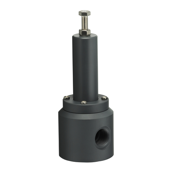
SERIES "RVT" RELIEF VALVES
determination
of
material
MAXIMUM INLET PRESSURES for WATER*
COLOR
at 77ºF (25ºC)
DARK GRAY
150 PSI 10 Bar
LIGHT GRAY
150 PSI 10 Bar
TRANSLUC. WHITE
150 PSI 10 Bar
TRANSLUC. WHITE
150 PSI 10 Bar
OPAQUE WHITE
150 PSI 10 Bar
PTFE tape will "string" as
INSTRUCTIONS
CAUTION: Series RVT is not a pop safety relief valve. It is not
intended for air or gas service. It does not regulate pressure
downstream of the valve. Connecting the outlet to a suction line
may cause air to be drawn into the line. Connecting the outlet to
a pressurized line or vessel may cause valve malfunction.
Plastic materials will degrade in ultraviolet (UV) light or sunlight.
Polypropylene and PVDF often look similar. Do not install in your
system if you are not sure.
at 104ºF (40ºC)
at MAX TEMP.
106 PSI 7 Bar
34 PSI @ 140ºF 2 Bar @ 60ºC
120 PSI 8 Bar
37 PSI @ 180ºF 2 Bar @ 80ºC
125 PSI 8 Bar
40 PSI @ 180ºF 2 Bar @ 80ºC
120 PSI 8 Bar
22 PSI @ 280ºF 1 Bar @ 140ºC
140 PSI 9 Bar
10 PSI @ 280ºF 69 Kpa @ 140ºC
CAUTION:
Connect to plastic pipe and fittings only; when using
metal pipe, install an intervening plastic fitting. Metal pipe and
straight threaded pipe tends to cut, stretch, and distort the
plastic bodies, resulting in cracking or leaking over time.
NON-THREADED CONNECTIONS
or heat fusion, follow the instructions supplied with the cement
or fusion equipment, of contact your distributor.
MOUNTING:
These valves are designed to be supported by
the piping. The piping must be properly supported, taking into
account the weight of the valve, piping, and process liquid.
– For solvent cementing
RVT-0219-I-1
Advertisement
Table of Contents

Summary of Contents for PLASTOMATIC RVT Series
- Page 1 INSTRUCTIONS SERIES “RVT” RELIEF VALVES INSTALLATION AND MAINTENANCE INSTRUCTIONS I. IMPORTANT – BEFORE INSTALLING Series RVT relief valves will open when inlet pressure exceeds CAUTION: Series RVT is not a pop safety relief valve. It is not the set pressure, when properly installed and used within the intended for air or gas service.
- Page 2 INSTRUCTIONS SERIES “RVT” RELIEF VALVES III. OPERATION IV. PRESSURE SETTING INSTRUCTIONS RELIEF OPERATION Series RVT pressure relief valves sense inlet pressure; The function of a relief valve is to protect a pressurized therefore it may be helpful to install a pressure gauge at the pipeline, vessel, or other similar system from excessive inlet of the valve for setting.
- Page 3 NEED HELP? Hold the shaft with a rubber sheet Call 1-973-256-3000, fax to 1-973-256-4745, or glove, and screw on until tight. or e-mail to info@plastomatic.com, Do not overtighten or use any material which may scratch the for Tech Support. teflon shaft.
- Page 4 INSTRUCTIONS SERIES “RVT” RELIEF VALVES INSTALLATION AND MAINTENANCE INSTRUCTIONS RVT050 SEAL KIT Item Qty. Description SEAT GASKET 1 or 2 SEAT RETAINER O-RING U-CUP SEAL SPREADER SEAL* BODY O-RING * The “spreader seal” is the o-ring that is nicked or cut to permit expansion. RVT075, RVT100, RVT125, RVT150, RVT200 SEAL KIT *NOTE: 1"...
Need help?
Do you have a question about the RVT Series and is the answer not in the manual?
Questions and answers