Advertisement
Quick Links
Advertisement

Summary of Contents for Whadda WSEDU02
- Page 1 ASSEMBLY MANUAL SOLAR ENERGY EXPERIMENT KIT WSEDU02 whadda.com AGE 12+...
- Page 3 10 exciting solar projects which you can actually use. PROJECTS FEATURED IN THIS BOX: (pag.8) Solar - Powered LED ................. As long as the sun shines, the LED will light (pag.10) Flashing Solar LED ..................Solar-powered attention grabber Solar - Powered Cricket. (pag.12) ........
- Page 4 PARTS SUPPLIED WITH THIS KIT: 4V / 30mA solar cell This device will convert sunlight into electricity, which we will use in all projects. More light means (Velleman part# YH-39X35) more electricity. Point the black surface towards the sun. Breadboard Will hold all your experiments.
- Page 5 Ultrabright yellow & red LED Wire jumper Just a piece of bare wire to connect two points in a circuit. Flat side Shortest leg = (-) The yellow & red LED provide a lot of light and require a very low current to operate.
-
Page 6: Battery Holder
Diode Diodes allow the current to flow in only one direction, from (+) to (–). Current flow in the opposite direction is blocked. (Velleman part# BAT85) A special case: Zener diodes Zener diodes allow the current to flow from (+) to (-), as regular diodes do. If you invert the polarity, they drop a certain voltage, which can be found on the body of the zener diode, e.g. -
Page 7: Microcontroller (Μc)
A transistor is an amplification device. By means of a small current, Transistors a much larger current is controlled. Transistors come in two flavours, NPN and PNP-types, depending on the polarity. With this C B E kit, you receive a BC557 (PNP) transistor. A transistor has 3 pins: Base, Emitter and Collector. - Page 8 PROJECT 1: SOLAR POWERED LED As long as the sun shines, the led will light...
- Page 9 Required parts: Solar cell, 100 ohm resistor (brown black brown gold), yellow led How it works: A closed circuit is required to make the current flow. Current flows from the (+) of the solar cell trough resistor to the (+) of the led and via the (-) of the led back to the solar cell.
- Page 10 PROJECT 2: SOLAR FLASHING LED Solar powered attention grabber µC Jumper wire...
- Page 11 Required parts: Solar cell, 100 ohm resistor (brown black brown gold), yellow led, microcontroller (µC), wire jumper. How it works: The controller requires 2-5V to operate. This PIC10 F20 0-I/PG voltage is supplied by the solar panel. The microcontroller is pre-programmed with software GP0 /ICSPDAT that turns the output on and off...
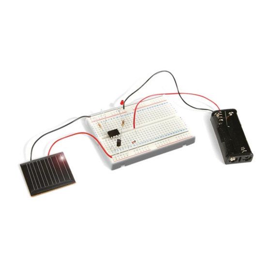
- Page 12 PROJECT 3: SOLAR POWERED CRICKET As long as the sun shines, the circket will Jumper wire µC Jumper wire...
- Page 13 Required parts: Solar cell, microcontroller (µC), piezo sounder, wire jumpers How it works: The controller µC requires 2-5V to operate. This voltage is supplied by the solar panel. The microcontroller is pre-programmed with software that generates a realistic cricket chirp. The chirp signal is output PIC10 F20 0-I/PG via pin 4.
- Page 14 PROJECT 4: SIMPLE SOLAR BATTERY CHARGER Insert two AAA 1.2V rechargeable batteries* Free energy to keep your batteries in *Not included...
- Page 15 Required parts: Solar cell, BAT85 diode, battery holder for two AAA batteries, two AAA 1.2V rechargeable batteries. How it works: As long as the solar cell is exposed to light, a BAT8 5 current will flow from the solar cell via the diode trough the batteries and back to the solar cell.
- Page 16 PROJECT 5: SOLAR BATTERY CHARGER WITH ‘CHARGE’-INDICATOR A led turns on when the batteries are charging... Insert two AAA 1.2V rechargeable batteries* *Not included...
- Page 17 Required parts: Solar cell, BC557 transistor, 4K7 resistor (yellow, purple, red, gold), yellow led, battery holder for two AAA batteries, How it works: When the sun shines, a current flows from the (+) of the solar cell via the Emitter/Base of the transistor trough the batteries and back to the solar cell.
- Page 18 PROJECT 6: SOLAR MUSICAL INSTRUMENT More light = higher note Wire Jumper wire µC...
- Page 19 Required parts: Solar cell, microcontroller (µC), 2x 4K7 resistor (yellow, purple, red, gold), 470 ohm resistor (yellow, purple, brown, gold), 2V4 zener diode, piezo sounder, wire jumpers, wire. How it works: The solar cell provides the supply voltage for the PIC10 F22 0 microcontroller.
- Page 20 PROJECT 7: IR REMOTE CONTROL TESTER ‘Listen’ to your IR remote +/- 5cm...
- Page 21 Required parts: Solar cell, piezo sounder, IR remote control (option). How it works: Solar cells are sensitive to infrared light. When hit by infrared light, they generate a voltage, like they do with sunlight. IR remote controls generate a beam of BUZ1 infrared light when they are operated.
- Page 22 PROJECT 8: SOLAR GARDEN LIGHT Led turns on at dusk and turns off at dawn, fully automatic Insert two AAA 1.2V Jumper wire rechargeable batteries* *Not included...
- Page 23 Required parts: Solar cell, BC557 transistor, 4K7 resistor (yellow, purple, red, gold), 470 ohm resistor (yellow, purple, brown, gold), BAT85 diode, yellow led, battery holder for two AAA batteries, two AAA 1.2V rechargeable batteries, jumper wire. Led current How it works: When the sun shines, the (only at night) voltage generated by the solar cell will be higher than the voltage of the batteries, so a...
- Page 24 PROJECT 9: SOLAR MOTION DETECTOR / BEAM BREAK DETECTOR Announce wanted or unwanted guests Jumper wire µC Wire...
- Page 25 Required parts: Solar cell, microcontroller (µC), 2x 4K7 resistor (yellow, purple, red, gold), 470 ohm resistor, (yellow, purple, brown, gold), 2V4 zener diode, piezo sounder, wire. How it works: The solar cell provides the PIC10 F22 0 supply voltage for the microcontroller. Once the 47 0 controller receives 2VDC it starts running its internal program.
- Page 26 PROJECT 10: SOLAR POWERED ‘ALARM ARMED’-LED Insert two AAA 1.2V rechargeable batteries* Charges during the day, scares burglars at night Jumper wire µC *Not included Jumper wire...
- Page 27 Required parts: Solar cell, microcontroller (µC), 4K7 resistor (yellow, purple, red, gold), 100 ohm resistor, (brown, black, brown, gold), BAT85 diode, BC557 transistor, battery How it works: When the sun shines, the voltage generated by the solar cell will be higher than the voltage of the batteries, so a current will flow from the solar cell to the BAT8 5...
- Page 28 Whadda.com Modifications and typographical errors reserved. © Velleman Group nv, Legen Heirweg 33 - 9890 Gavere (België) WSEDU02 - 02082021...
Need help?
Do you have a question about the WSEDU02 and is the answer not in the manual?
Questions and answers