Table of Contents
Advertisement
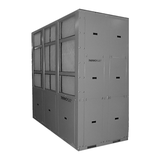
WATER COOLED HEAT PUMPS
VERTICAL MODELS
SIZE 160 TO 720
INSTALLATION, OPERATION AND MAINTENANCE
SERIES
KHPE-160 / KHP-720
Each heat pump has been operated and
verified out prior to shipment. Failure to
operate after installation indicates damage in
transit or improper installation.
INSPECTION
Check packaging during unloading. Note
transit damage on all copies of bill of lading.
Inspect heat pumps for hidden shipping
damage after packaging is removed.
Purchaser must file transit damage claims
promptly with Freight Company.
HANDLING
Always handle units upright on their base.
Moving a vertical unit on its side may
damage internal parts and displace oil from
the compressor's crankcase.
STORAGE
If job site storage is necessary, place the unit
in a clean, warm, dry area. Follow
instructions under Handling.
PLACEMENT
Install heat pumps in a level plane and locate unit to ensure that proper access is available to all
service panels including that of filter removal.
For Vertical Units: Install the heat pump with a piece of sound insulating material between unit and
floor to avoid possible transmission of noise into the building structure. (rubber backed carpeting
will suffice for vertical models). For units installed in closets adjacent to conditioned space,
provide insulated return air ducting with at least one 90o elbow or provide a sound baffle between
the return air grill and unit filter.
Advertisement
Table of Contents

Summary of Contents for ThermoPlus Air KHPE Series
- Page 1 WATER COOLED HEAT PUMPS VERTICAL MODELS SIZE 160 TO 720 INSTALLATION, OPERATION AND MAINTENANCE SERIES KHPE-160 / KHP-720 Each heat pump has been operated and verified out prior to shipment. Failure to operate after installation indicates damage in transit or improper installation. INSPECTION Check packaging during unloading.
-
Page 2: Condensate Drainage
WIRING All wiring should conform to the CEC and/or local code requirements. Power disconnect shall be field provided (by others). The wiring diagram is located on electrical box cover. Make certain the line voltage and the 24 volt control circuit are properly identified and wired in accordance with the unit wiring diagram. -
Page 3: Water Supply
WATER SUPPLY (UNIT CONNECTED ON OPEN WATER CIRCUIT) The source of water for heat pump operation is the responsibility of the owner and/or the installing contractor. The heat pump must not function without water, and predetermined flow rates (l/s or USGPM) must be maintained for the unit to operate at rated capacity. - Page 4 WIRING - LINE VOLTAGE Check main power voltage. Refer to unit wiring diagram and make changes (if required) to permit the unit to operate on the available supply voltage. Connect power as per the unit-wiring diagram, conforming to the local and national electrical code requirements CONNECTION AND LOCATION OF THERMOSTAT Wiring the thermostat to the unit should be done as per the wiring diagram (inside the panel of the electrical box on the vertical units and on the inside of the service panel for horizontal units).
-
Page 5: Start-Up Instructions
START UP INSTRUCTIONS After installation of unit and the ductwork, water and condensate connections, the wiring in accordance with preceding instructions, the unit is ready for start-up. Check all wire connections to the unit and to external control devices for tightness. ... -
Page 6: Operation
OPERATION These units c/w multiple compressors and independent refrigeration circuits. (4 compressors and 4 circuits for a KAC- 720.) If the demand requires more than one compressor to operate, a time delay relay prevents them from starting at the same time. -
Page 7: Thermostatic Expansion Valves
units only) Each refrigeration circuit consists of an adjustable direct acting water regulating valve. The valve is a pressure actuated modulating valve that is suitable for either closed or open systems. This valve is primarily used to regulate the flow of water or glycol to the water-cooled condenser in each refrigerant circuit. -
Page 8: Economizer Control
OPTIONS WATERSIDE ECONOMISER A waterside economizer can be used where the unit’s entering water temperature is between 45 and 55° F. The economizer coil will act as the first stage of cooling if the water is cold enough. If the economizer is unable to maintain the zone or supply air temperature set point, one stage of DX cooling will also come on to meet the required set point.
Need help?
Do you have a question about the KHPE Series and is the answer not in the manual?
Questions and answers