
Summary of Contents for Grin V4
- Page 1 Baserunner Controller User Manual Rev 1.0 The V4 Baserunner Motor Controller User Manual – Rev 1.0 Grin Technologies Ltd Vancouver, BC, Canada (604) 569-0902 email: info@ebikes.ca web: www.ebikes.ca Copyright © 2021...
-
Page 2: Table Of Contents
Baserunner Controller User Manual Rev 1.0 Table of Contents 1 Introduction.................3 2 Connectors................4 2.1 Battery Leads....................4 2.2 Motor Cable.....................4 2.3 Cycle Analyst WP8 Plug.................5 2.4 Mains Signals Plug..................5 2.5 PAS / Torque Plug...................5 2.6 Communication Port..................6 3 Wiring Strategies..............6 3.1 Cycle Analyst Based Hookup.................6 3.2 3rd Party Display Hookup................7 3.3 Headless System....................8 4 Controller Mounting............9... -
Page 3: Introduction
(FOC). We’ve worked hard to make this a versatile after-market device that can pair with a wide range of ebike systems. This manual covers the V4 models of our Baserunner_Z9 and Baserunner_L10 controllers, first released in 2021. -
Page 4: Connectors
Rev 1.0 2 Connectors The V4 Baserunners achieve maximum versatility with minimal wiring. A pair of +- battery leads supply power, a single overmolded cable carries all motor signals, and three waterproof signal plugs support a range of hookup strategies. -
Page 5: Cycle Analyst Wp8 Plug
WP8 Pinout 2.4 Mains Signals Plug New to the V4 devices is a Cusmade Signal D 1109 Connector that supports conventional ebike wiring strategies for 3 party display consoles. -
Page 6: Communication Port
Micro USB or USB-C port. 3 Wiring Strategies The V4 Baserunners can be hooked up to to the controls of an ebike system in one of three ways. Either under the control of a V3 Cycle Anlayst, under the control of a 3 party display, or headless with no display at all. -
Page 7: 3Rd Party Display Hookup
6 pin PAS plug on the controller, with the Baserunner controller specially configured to respond to PAS signals. At present Grin only provides support for this hookup to OEM customers purchasing complete systems with Third party displays using the KM5s protocol, and does not offer support or the components for this at the retail level. -
Page 8: Headless System
Baserunner Controller User Manual Rev 1.0 3.3 Headless System Finally, the Baserunner can be run with only a PAS / Torque sensor wired up to the 6 pin PAS plug, or just a throttle on the Mains plug. In this arrangement, it is essential to wire up the on/off power switch on either the WP8 plug or the Mains connector for the controller to turn on. -
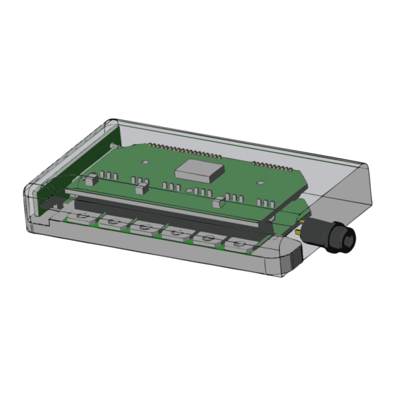
Page 9: Controller Mounting
Reention and Hailong downtube battery casings. Grin supplies these modified controller housings with their pockets milled out to fit the Baserunner. For use in other applications, Grin also produces mounts to secure the Baserunner to a flanged plate, a round tube, and the fender bolt of a Brompton bicycle fork. -
Page 10: Parameter Tuning
With the Baserunner powered on, plug in the TTL->USB cable from your computer to the Baserunner. When you launch the Phaserunner software, it should open to the “Basic Setup” tab and indicate “V4 Baserunner connected” on the top If you see “Controller is not connected,” check that the selected serial port is correct and that the USB->TTL device shows up in your device manager as a... -
Page 11: Importing Default Parameters
“Battery Limits.” If your motor is not listed on the “Import Defaults” window, try choosing “Download Latest Defaults from Grin” and follow the prompts. If default settings for your motor are still not available, proceed to the “Motor Autotune” section that follows. - Page 12 Crystalyte 400, Wilderness Energy BionX PL350 Crystalyte 5300, 5400 TDCM IGH Crysatlyte NSM, SAW Grin All Axle, Crysatlyte H, Nine Continent, MXUS and Other 205mm DD Motors Magic Pie 3, Other 273mm DD Motors, RH212 Bafang BPM, Bafang CST Bafang G01, MXUS XF07...
- Page 13 Baserunner Controller User Manual Rev 1.0 Once the “kV” and the “Number of Pole Pair” values are entered, launch the “Static Test.” This test will produce three short buzzing sounds, and determine the inductance and resistance of the motor windings. The resulting values will be shown on the screen.
-
Page 14: Battery Limits
Baserunner Controller User Manual Rev 1.0 During the spinning test, the Baserunner will start the motor in sensorless mode. If the motor fails to spin and just starts and stutters a few times, adjust the sensorless starting parameters as described in section 5.5, “Tuning the Sensorless Self Start,”... -
Page 15: Motor Phase Current And Power Settings
Baserunner Controller User Manual Rev 1.0 The “Low Voltage Cutoff (Start)” and “Low Voltage Cutoff (End)” values can be set just above the BMS cutoff point of your battery. If you are using a V3 Cycle Analyst, we recommend leaving these values at the default 19.5/19.0 volts and use the CA3’s low voltage cutoff feature instead. -
Page 16: Tuning The Sensorless Self Start
Baserunner Controller User Manual Rev 1.0 5.5 Tuning the Sensorless Self Start Advanced Setup If you are running in sensorless mode, then you may need to tweak the sensorless self start behaviour. When the brushless motor is run without hall sensors and started from a complete stop, the motor controller attempts to ramp up the motor’s rpm to a minimum speed so that it can latch onto the rotation (closed loop). -
Page 17: Throttle And Regen Voltage Maps
Baserunner Controller User Manual Rev 1.0 while a much longer ramp is required if you need to start moving without pedaling. If you feel the motor repeatedly trying to start when applying throttle, the “Autostart Ramp” may be too aggressive, or the “Autostart Max RPM” may be too low. -
Page 18: Field Weakening For Speed Boost
Baserunner Controller User Manual Rev 1.0 The regen voltage is mapped by default so that regenerative braking starts at 0.8V and reaches maximum intensity at 0.0V. This way there is no overlap between the throttle region and the braking region and a single wire can control both ranges. -
Page 19: Virtual Electronics Freewheeling
Baserunner Controller User Manual Rev 1.0 The following graph shows a large direct drive hub motor’s rpm as a function of field weakening current. The upper black line is the motor’s measured rpm, while the initially lower yellow line is the no-load current draw, reflecting the amount of extra power lost due to field weakening. -
Page 20: Additional Details
Baserunner Controller User Manual Rev 1.0 unloaded motor current. The “Motor Stall Timeout” setting determines when this injection current will stop once the motor comes to a stop. Once the values for “Virtual Electronic Freewheeling” are set, the controller will draw about 10-40 watts in order to overcome the motor’s drag. -
Page 21: Demux Circuitry
6.4 Wheel Speed Sensing The V4 Baserunner will automatically select the source of the wheel speed signal for vehicle speed measurement. If there are speed pulses present on the wheel speed sensor pin then these will be mapped automatically to the Cycle Analyst plug. -
Page 22: Motor Thermal Rollback Via Baserunner
Baserunner Controller User Manual Rev 1.0 6.5 Motor Thermal Rollback via Baserunner To use the controller's built in motor temperature rollback, it is necessary to create a voltage / temperature map of this signal by putting appropriate values in address 93-98 from the “edit parameters”... -
Page 23: Cycle Analyst Settings
Baserunner Controller User Manual Rev 1.0 Throttle + Brake Map for Shorted Signals Example Map with Separate Regen Throttle 7 Cycle Analyst Settings Current Sensing [ Cal->RShunt ] The Baserunner uses a 1.00 +- 0.02 mW shunt resistor for current sensing. The exact calibrated value is laser engraved on the controller heatsink. -
Page 24: Led Flash Codes
Baserunner Controller User Manual Rev 1.0 8 LED Flash Codes The embedded LED on the side of the controller provides a useful status indicator. It will flash according to the following table if the controller detects any faults. Some faults will clear automatically once the condition clears, such as “Throttle Voltage Outside of Range,”... - Page 25 Baserunner Controller User Manual Rev 1.0 The LED may also flash several different warning codes. These warnings do not stop the controller from running and will appear as various limits are reached in normal operation, they are not usually a cause for any concern. Table 3: Baserunner LED Warning Flash Codes Communication Timeout Hall Sensor...
-
Page 26: Specifications
Baserunner Controller User Manual Rev 1.0 9 Specifications 9.1.1 Electrical Peak Battery Current Programmable up to 55A (Z9) or 80A (L10)* Peak Phase Current Programmable up to 55A (Z9) or 80A (L10)* Peak Regen Phase Current Programmable up to 55A (Z9) or 80A (L10)* Continuous Phase Current Approximately 35A (Z9), 50A (L10) at thermal rollback, varies with air flow and heat sinking...
Need help?
Do you have a question about the V4 and is the answer not in the manual?
Questions and answers