
Summary of Contents for Sanken LeaderSamco NS
- Page 1 Vector Control Drive Technical Manual Three Phase 400V Input: 0.75kW~18.5kW Single Phase 200V Input: 0.4kW ~0.75kW...
-
Page 2: Table Of Contents
1. Safety ......................... 7 1-1 Important notes ....................7 1-2 Instructions for use ..................7 1-3 Instructions for installation ................8 1-4 Instructions for transportation and relocation ..........8 1-5 Instructions for wiring ..................7 1-6 Instructions for operation ................10 1-7 Instructions for maintenance and examination .......... - Page 3 4-4 External braking resistor selection suggestions: ..........32 4-5 Control circuit terminal configuration ............. 33 4-5-1 Wire size ................33 4-5-2 Arrangement of control circuit terminals ........ 33 4-6 Connection to peripheric equipment ............. 35 4-6-1 Peripheric equipment connection diagram ........... 35 4-6-2 Connection instructions for peripheric equipment .........
- Page 4 7-2-1 Basic operation functions F10xx~F13xx ..........51 7-2-2 Input/output related functions F14xx~F16xx ........58 7-2-3 System related functions F16xx~F18xx ..........64 7-2-4 Special functions F19xx~F20xx ............67 7-2-5 Pattern movement functions F21xx~F22xx ........66 7-2-6 Display functions F23xx ..............71 7-2-7 PID functions F30xx~F33xx ...............
- Page 5 11-3 Communication function specification ......103 11-4 Storage Environment ........104 11-5 Overall dimensions ........105 12 Peripheric equipment and optional parts.............. 100...
- Page 6 Thank you for choosing NS vector control inverter of SankenLD. [For safety purposes] Please read carefully this manual before using this device. Please place this manual near the device for reference after finishing reading. Use and meanings of safety warnings and notes Meanings of graphic symbols...
-
Page 8: Safety
1. Safety Important notes Instructions for use... -
Page 9: Instructions For Installation
Instructions for installation Instructions for transportation and relocation... - Page 10 Instructions for wiring...
-
Page 11: Instructions For Operation
Instructions for operation Instructions for maintenance and examination -10-... -
Page 12: Instructions For Disposal
Instructions for disposal other notes -11-... -
Page 13: Product Confirmation And Notes
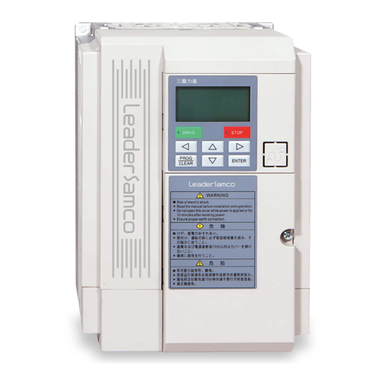
2. Product confirmation and notes Product confirmation ■ Appearance of the inverter: Illustration of then main body of NS vector control inverter (NS-4A017-B for instance) ■ After unpacking, please confirm: Whether the outer case is damaged. If in doubt, please contact your local sales representative. You may find one copy of this manual in the packing case, please conserve it appropriately in order to better leverage the functions of the inverter. -
Page 14: Type Code
Type code Label Please refer to this label and Standard Specifications for product model and capacity against order. -13-... -
Page 15: Notes Before Use
2-4 Notes before use: ■Failure to observe the following warnings may cause serious damage to the inverter: ◆Never connect the power cable (input) to the output port of the motor! Otherwise, serious damages may be casued to the inverter! ◆Do not connect the power input cable to any terminal other than R, S, T! Otherwise, serious damages may be caused to the inverter! ◆The output port of the inverter should never be connected to capactive loads! Otherwise, damages may be caused! -
Page 16: Installation
3. Installation Installation lacation and storage Table 3-1 Working environment parameters Ambient temperature -10℃~+50℃(ice free); heavy overload, -10℃~+40℃(ice free); light overload Storage temperature -20℃~+65℃ (short-term storage in transportation)※4 Relative humidity Below 95%RH (no dewing) Altitude Below altitude of 3000m (lower current when over 1000m) Vibration Below 5.9m/s (0.6G) (JIS C 60068-2-6 standard;... - Page 17 ■ Installation of inverters in horizontally parallel spots: When installing inverters side by side, please ensure a distance of at least 5cm between side covers of the inverter and inner walls of the cabinet, between one inverter and another. Otherwise, heat dissipation of inverters may be insufficient.
- Page 18 ■ Installation of inverters in vertically parallel spots: Whenn installing inverters in vertically parallel spots, please ensure a distance of at least 20cm between side covers of the inverter and inner walls of the cabinet, between one inverter and another. Ensure as well efficient ventilation and cooling for each inverter.
- Page 19 ■ Installation location of ventilators in the cabinet: ■ Special notes: ◆ When several inverters are installed in the control cabinet, ventilators must be set up in proper spots inside the cabinet. ◆ Make sure the air brought from outside of the cabinet flows through the heating dissipation passage of the inverter, efficiently taking away the heat generated while the inverter is running.
-
Page 20: Mount And Remove The
Mount and remove the front cover (1) Remove front cover Remove the M4 screw, follow the diagram below to proceed the removing. ◆ Remove the front cover only while main circuit wiring or control circuit wiring. -19-... - Page 21 (2) Change ventilator Only proceed when it is necessary to change ventilator. (3) Mounting For mounting, proceed in reverse order of disassembling. -20-...
-
Page 22: Connection Layout
4. Connection layout Terminal power connection diagram -21-... -
Page 23: Main Circuit Terminal Structure
Main circuit terminal structure 4-2-1 Description of main circuit terminals Terminal symbol Name Description R,S,T Power input terminal Terminal connected three-phase AC, no particular requirement for phase sequence U,V,W Inverter output terminal Terminal connected to three-phase induction motor P,P1 reactor connection Terminal connected to DC reactor (while connecting to terminal... -
Page 24: Main Circuit Terminal Layout
4-2-2 Main circuit terminal layout 1.NS-4A003-B、NS-4A004-B、NS-4A006-B NS-2A003-A、NS-2A004-A -23-... - Page 25 2.NS-4A009-B、NS-4A013-B、NS-4A017-B -24-...
- Page 26 3.NS-4A024-B、NS-4A032-B、NS-4A038-B、NS-4A046-B -25-...
-
Page 27: Main Circuit Terminal Connection Diagram
4-2-3 Main circuit terminal connection diagram 400V series connection diagram: NS-4A003-B,NS-4A004-B,NS-4A006-B NS-4A009-B,NS-4A013-B,NS-4A017-B,NS-4A024-B,NS-4A032-B,NS-4A038-B NS-4A046-B -26-... - Page 28 200V series connection diagram: NS-2A003-A,NS-2A004-A ◆Note: Input power cable L and N of single-phase 200V series are connected to R/L and S/L1 terminals, while T/L2 terminals remain vacant. -27-...
- Page 29 ◎Please refer to 4-5-4 for capacity and cable diameter of MCCB and MC. For terminals of power cable and motor cable, apply crimped cable with conduit. MC (Magnetic contactor) MCCB Model (circuit breaker) Current rating Working current rating[A] NS-4A003-B NS-4A004-B NS-4A006-B NS-4A009-B NS-4A013-B...
-
Page 30: Recommended Wire Size
4-2-4 Recommended wire size Main circuit Recommended wire size [mm Tightening Maximum Screw torque size Terminal P, P1 Ground diameter R, S, T U, V, W N·m symbol PR, X wire NS-4A003-B 2.0 (2.0) 2.0 (2.0) 2.0 (2.0) 2.0 (2.0) 2.0 (2.0) 2.0 (2.0) NS-4A004-B... -
Page 31: Wiring
Wiring 4-3-1 Notes for wiring: ◆The input power of the inverter must be disconnected and there must be no applied voltage on the input port while wiring! ◆Make sure no chip of wires enters inside the inverter while wiring. ◆Circuit breakers must be installed between the power source and input power terminals (R, S, T). To ensure system safety, please install a magnetic contactor between the circuit breaker and input power. - Page 32 ◆Please do not share the ground wire with welder or power unit. Otherwise, disturbance or other abnormality may be caused. ◆When several inverter are running at the same time, please make sure the ground wire is not a closed loop. (a) Correct (b) correct (c) wrong...
-
Page 33: External Braking Resistor Selection Suggestions
External braking resistor selection suggestions: External braking resistor (recommended) External braking resistor (limit value) Model Capacity ※1 Capacity ※1 Resistance value Resistance value NS-4A003-B Above 700Ω 100W Above 420Ω 300W NS-4A004-B Above 700Ω 100W Above 420Ω 300W NS-4A006-B Above 320Ω 200W Above 190Ω... -
Page 34: Control Circuit Terminal Configuration
Control circuit terminal configuration 4-5-1 Wire size Terminal screw diameter: M3 Recommended wire size: 0.75[mm Tightening torque: 0.5[N•m] 4-5-2 Arrangement of control circuit terminals ■ Special notes: ▲ never connect strong-voltage power to control terminal! Otherwise, the main control panel will be burned. ▲... - Page 35 4-5-3 Functions of control circuit terminal (jumper wire) Terminal Type Terminal name Function description Nominal specifications symbol Digital signal ground Digital signal ground Total current consumption below 100mA 24V power ground Multi-function Signal effective in case input nput resistance: around 6.6kΩ Multi-function input of short circuit of DIX and ~...
-
Page 36: Connection To Peripheric Equipment
4-6 Connection to peripheric equipment 4-6-1 Peripheric equipment connection diagram -35-... -
Page 37: Connection Instructions For Peripheric Equipment
4-6-2 Connection instructions for peripheric equipment Objective and configuration conditions of peripheric equipment: Name Objective of usage and detailed description When the power system voltage does not match the inverter’s nominal input voltage, please use the input power inverter to convert it. Input transformer When several inverters are functioning at the same time, installing an input power transformer helps decrease impacts caused by current of higher harmonics on other load... -
Page 38: Operation Panel
5. Operation panel Names and functions of each part of the operation panel Instructions for operation panel: LCD display can present rich content to allow a full understanding of the inverter’s status. The 5-digit 7-segment LCD display of the main screen can show segment codes. Through left/right button switching over or parameter setting, segment codes can clearly present current operating frequency, output current, rotating speed, load rate, output voltage, pressure value, set value and alarm content. -
Page 39: Instructions For Operation Panel Buttons
direct operation of increasing and decreasing. 5-2 Instructions for operation panel buttons Mentioned in this Button name Button symbol Function overview manual as RUN botton ●Start forward/reverse rotation 【DRIVE】 ●stop running STOP button ●In case of alarm, it can be used to clear the 【STOP】... -
Page 40: Operation Panel Display Mode
Operation panel display mode The main and secondary screens of the operation panel have two modes 【status display】 and 【function code display】. These two modes can be switched over by 【PROG】 button. Display mode Display content Status display Status of the inverter while RUN and STOP <frequency>... -
Page 41: Alarm Display
Table 5-2 Content of function mode display Function status Display content STOP RUN indicator light, STOP indicator light RUN indicator light, STOP indicator light malfunction RUN indicator light, STOP indicator light Light on flashing light off Monitor mode display indicates content of segment code display of 7-segment LCD on the main screen Table 5-3 Content display of monitor mode Display content... -
Page 42: Basic Operations
Operation demonstration: switch from 5Hz to 45Hz Operation Display Description Status monitoring display (frequency display) The entered value shows at the rightmost digit (this digit flashes, which indicates this digit is modifiable) (※1) 【ENTER】 Each time the 【<】 button is pushed,the flash moves one digit leftwards. -
Page 43: Operation Confirmation
Push of 【∧】 button can modify the parameter set number into 14, and the parameter set number 14 flashes on the secondary screen. 【∧】*4 This number is modifiable. Push of 【>】 button leads to the mode of parameter number modification, and the parameter number 01 flashes. This number is modifiable. -
Page 44: Special Functions
Push 【∧】 button and modify the value to 10. 【∧】 Push 【ENTER】 button, the main screen will show the set value and the secondary screen will show flashing 【ENTER】 , which indicates the set value is under confirmation (※1) Push 【∧】 button again, the new setting is confirmed and the interface switches back to function code selection 【∧】... - Page 45 When the indexing is finished, on the secondary screen flashes the modified function code If there is no modification, the word “End” flashes on the secondary screen, and the current value of the After the completionof related parameter shows on the secondary screen. 或...
- Page 46 5-5-2 Alarm status confirmation Alarm status confirmation is a function that shows the status of the inverter at alarm. This function can make confirmation on 5 latest alarm status through function codes F1806~F1810. In case of new alarm, the earliest alarm will be deleted. F1806 stands for the latest alarm and F1810 stands for the earliest alarm.
-
Page 47: List Of Monitor Display
When the function code is set as F1805=9, alarm record can be deleted. At this point, all alarm records from F1806 to F1810 will be deleted. ※1: Denotations Denotation Meaning Unit of measurement Alarm name Output frequency Output current Output voltage DC voltage Output power Heat sink... -
Page 48: Functioning
Functioning Examination before functioning 6-1-1 Confirmation before connection to power supply After wiring and before connection to power supply, please examine following items. Table 6-1 Items to be examined before connection to power supply Item Content power voltage confirmation Whether the power voltage is consistent with the capacity and ... -
Page 49: Test Run Of The Inverter
6-1-3 Test run of the inverter In order to confirm basic functioning specifications of the inverter, it is recommended to run tests and confirm all the codes in factory settings. This operation relies on the LCD operation panel included in the inverter, so please refer to instructions on LCD operation panel usage in Chapiter 5. - Page 50 Step 5: Power off: When confirmations are complete, please cut off the power supply. Since there is electric energy stored in the internal electrolytic capacitor, the LCD of the inverter will go out in a certain time. However, there is still some remaining voltage inside, so please do not start connecting or disconnecting wires right after the power is cut off, and wait until CHAGE light is completely off.
-
Page 51: Function Codes
Function codes Instructions on application partition by function codes By changing function codes, the action of the inverter can be modified. Function codes can be partitioned by functions into “functional application blocks”. Function category Functional application code Functional application block name F10xx Basic functions F11xx... -
Page 52: Table Of Function Codes
7-2 Table of function codes 7-2-1 Basic operation functions F10xx~F13xx Basic operation functions F10xx~F13xx Minimum Factory Function name Data content Code unit value 1001 Motor control mode options 1: V∕f control mode 2: speed control (speed sensorless vector control) 10: motor parameter automatic measurement mode 1 11: motor constant automatic measurement mode 2 40: V•f separation control 1002... - Page 53 Minimum Factory Code Function name Data content unit value 5~600Hz 1007 Maximum frequency 0.01Hz 0.05~200Hz 1008 Minimum frequency 0.01Hz 0.05 ※1 1009 Carrier frequency adjustment 1: arbitrary soft carrier method 1 2: arbitrary soft carrier method 2 3: arbitrary soft carrier method 3 4: arbitrary soft carrier method 4 5~130 1010...
- Page 54 Minimum Factory Code Function name Data content unit value Start of S-shaped 0~200% 1028 acceleration End of S-shaped 0~200% 1029 acceleration Gradient of middle of 2 0~100% 1030 S-shaped Acceleration Start of S-shaped 0~200% 1031 deceleration End of S-shaped 0~200% 1032 deceleration Gradient of middle of 2nd...
- Page 55 Minimum Factory Code Function name Data content unit value 0.05~60Hz 1103 Startup frequency 0.01Hz 0~20Hz 1104 Frequency of operation starting 0.01Hz 0~5 seconds 1105 Startup lag time second 0~120 seconds 1106 Startup timeout second 0.05~60Hz 1107 Startup timeout frequency 0.01Hz 1108 restart after Instantaneous stop 0: no restart...
- Page 56 Minimum Factory Code Function name Data content unit value 0.05~60Hz 1118 DC braking completion frequency 0.01Hz to stop 0.1~6500.0 seconds 1119 DC braking time T1 second 0.1~6500.0 seconds 1120 DC braking time T2 second 0.1~6500.0 seconds 1121 DC braking time T3 second 1~10 1122...
- Page 57 Minimum Factory Code Function name Data content unit value 1: unit free (magnification of F1203) 1202 Content options of status display 2: output voltage [V] 3: DC voltage [V] 4: active power [kW] 5: apparent power [kVA]. 6: heat Sink Temperature [℃] 7: instructed rotation speed [rpm] 8: PID1 feedback variable [Hz] 9: PID2 feedback variable [Hz]...
- Page 58 Minimum Factory Code Function name Data content unit value 1309 Movement direction switch 0: restart in reverse direction after breaking off controlled by V/f 1: continuous movement 0~99.99 seconds 1315 Minimum working time 0.01 second 5~600Hz [Hz] 1316 Second maximum frequency 0.01 [Hz] 5~600Hz [Hz] 1317...
-
Page 59: Input/Output Related Functions F14Xx~F16Xx
7-2-2 Input/output related functions F14xx~F16xx Input/output related functions F14xx~F16xx Code Minimum Factory Function name Data content unit value 0~± 600 [Hz] 1401 Offset frequency (VRF) 0.1 [Hz] (0V frequency) 0~± 600 [Hz] 1402 Gain frequency (VRF) 0.1 [Hz] (frequency of 5V or 10V) 0~±... - Page 60 Minimu Factory Code Function name Data content m unit value 1414 Input terminal DI1 definition 0: unused 1; FR, 2: RR, 3: 2DF, 1415 Input terminal DI2 definition 4: 3DF 5: MBS, 6: ES, 7: RST, 1416 Input terminal DI3 definition 8: AD2, 9: AD3, 10: JOG,...
- Page 61 Minimu Factory Code Function name Data content m unit value 1422 Reference frequency of pulse 1000 1000~60000 train input (corresponding to maximum frequency) 1423 VRF effective number of bits 1bit 7~10bit determination 1424 V/I effective number of bits 7~10bit 1bit determination 1426 Time constant of pulse train...
- Page 62 Code Minimum Factory Function name Data content unit value 1504 Built-in analog output 0: null function 2 1: set frequency [Hz] 2: output frequency [Hz] 3: PID1 feedback value [Hz] 4: PID2 feedback value [Hz] 5: output current [A] 6: output voltage [V] 7: DC voltage [V] 8: heat sink temperature [℃] 9: load rate [%] (electronic heat sensor accumulated value)
- Page 63 Minimum Factory Code Function name Data content unit value 0: unused, 1509 Options of output terminal DO1 1: running 1 2: undervoltage, 3: termination of pattern operation cycle, 4: running 2, 5: frequency consistency (Speed 1 frequency), 6: frequency consistency (Speed 1~16 frequency), 7: frequency completion, 8: overload warning signal (value of F1704), 9: electronic heat sensor warning signal (electronic heat...
- Page 64 Minimum Factory Code Function name Data content unit value 0: alarm contact, 1513 Options of relay 1: running 1, contact output 2: undervoltage, 3: termination of pattern operation cycle, 4: running 2, 5: frequency consistency (Speed 1 frequency), 6: frequency consistency (Speed 1~16 frequency), 7: frequency completion, 8: overload warning signal (value of F1704), 9: electronic heat sensor warning signal (electronic heat sensor...
-
Page 65: System Related Functions F16Xx~F18Xx
7-2-3 System related functions F16xx~F18xx System related functions F16xx~F18xx Minimu Factory Code Function name Data content m unit value 1601 Replication function 0: null (optional parts) 1: transmission of current code data to operation panel 2: transmission of content stored in operation panel to the main body (except for motor parameter determination) 3: transmission of content stored in operation panel to the main body (including motor parameter determination) - Page 66 Minimum Factory Code Function name Data content unit value 1703 constant-speed output current 0: null limiting 1: granted, V/f, (current acceleration/deceleration time) 2: granted, V/f, (first acceleration/deceleration time) 3: granted, V/f, (second acceleration/deceleration time) 4: granted, V/f, (third acceleration/deceleration time) 5: granted, V/f, (forth acceleration/deceleration time) 6: granted, V/f and vector control of speed (first acceleration/deceleration time)
- Page 67 Minimum Factory Code Function name Data content unit value 1710 Carrier frequency modifiable if 0: null temperature drops (only effective 1: function granted when Method A selected) 1801 Query of software version of Only for reading version inverter host 1802 Query of version of data stored in Only for reading version...
-
Page 68: Special Functions F19Xx~F20Xx
7-2-4 Special functions F19xx~F20xx Special functions F19xx~F20xx Minimu Factory Code Function name Data content m unit value 1901 Options of energy-saving modes 0: null 1: simple energy-saving mode (V/f mode) 2: automatic energy-saving mode 0~50% 1902 Simple energy-saving ratio 0~65000 seconds 1903 Simp0le energy-saving time 1 sec... -
Page 69: Pattern Movement Functions F21Xx~F22Xx
7-2-5 Pattern movement functions F21xx~F22xx Pattern movement functions F21xx~F22xx Minimum Factory Code Function name Data content unit value 0~600Hz 2101 Speed 1 frequency 0.01Hz 0~600Hz 2102 Speed 2 frequency 0.01Hz 0~600Hz 2103 Speed 3 frequency 0.01Hz 0~600Hz 2104 Speed 4 frequency 0.01Hz 0~600Hz 2105... - Page 70 Minimum Factory Code Function name Data content unit value 0~65000 seconds Movement timer T12 1 sec 2214 0~65000 seconds Movement timer T13 1 sec 2215 0~65000 seconds Movement timer T14 1 sec 2216 0~65000 seconds Movement timer T15 1 sec 2217 0~65000 seconds 1 sec...
- Page 71 Minimum Factory Code Function name Data content unit value 2231 Forward/reverse movement·accelration/deceleration in T11 2232 Forward/reverse movement·accelration/deceleration in T12 2233 Forward/reverse movement·accelration/deceleration in T13 2234 Forward/reverse movement·accelration/deceleration in T14 2235 Forward/reverse movement·accelration/deceleration in T15 2236 Analog input switch perturbation 0: no analog input 1: external analog VRF voltage (0~5V) modulation 2: external analog VRF voltage (0~10V or...
-
Page 72: Display Functions F23Xx
7-2-6 Display functions F23xx Display functions F23xx Minimum Factory Code Function name Data content unit value 1~16 2301 LCD contrast ratio adjustment 2303 LCD monitor 1 display options 0: no dispaly (main screen) (1-6) 1: frequency [Hz] 2: output current [A] 3: rotation speed [rpm] 4: load rate [%] 5: output voltage [V]... - Page 73 Minimum Factory Code Function name Data content unit value 2304 LCD monitor 2 display options 1: no unit (magnification of F1203) (secondary screen) 2: output voltage [V] 3: DC voltage [V] 4: active power [kW] 5: apperant power [kVA]. 6: heat sink temperature [℃] 7: command rotation speed [rpm] 8: PID1 feedback value [Hz] 9: PID2 feedback value [Hz]...
-
Page 74: Pid Functions F30Xx~F33Xx
7-2-7 PID functions F30xx~F33xx PID functions F30xx~F33xx Minimum Factory Code Function name Data content unit value 3001 PID1 command value input 1: frequency 2: external analog VRF voltage (0~5V) switch 3: external analog VRF voltage (0~10Vorpotentiometer) 4: external analog V/I voltage (0~5V) 5: external analog V/I voltage (0~10Vorpotentiometer) 9: external analog V/I current (4~20mA) 11: function code setting (F3017) - Page 75 Minimum Factory Code Function name Data content unit value 3011 PID1 calculus of polarity switching 1: command value-feedback value 2: feedback value- command value 3012 PID1 gain polarity switching 1: same gain for positive and negative deviations 2: different gain for positive and negative deviations 0~50 3013...
- Page 76 Minimum Factory Code Function name Data content unit value 3102 PID2 feedback 0: no input 1: external analog VRF voltage (0~5V) input switch 2: external analog VRF voltage (0~10V or potentiometer) 3: external analog V/I voltage (0~5V) 4: external analog V/I voltage (0~10V or potentiometer) 8: external analog V/I current (4~20mA) 10: communication method -75-...
- Page 77 Minimum Factory Code Function name Data content unit value 0~100 3103 PID2 control of proportional gain 0.01 0.01~100 seconds 3104 PID2 control of integration time 0.01 second 0~100 seconds 3105 PID2 control of differentiation 0.01 second time 5~100% (maximum frequency reference) 3106 PID2 control of reference value 0.1%...
- Page 78 Minimum Factory Code Function name Data content unit value 0~400Hz 3119 PID2 control of corresponding 0.01Hz frequency of maximum command value 3123 PID starting method options 1: direct launching method 2: launching method by conditions 3124 PID termination method options 1: direct termination method 2: termination method by conditions 1~100% (maximum frequency standard)
- Page 79 Minimum Factory Code Function name Data content unit value 3201 PID control of action 0: open-loop control options 1: PID1 control 2: PID2 control 4: PID control of external terminal switching 5: PID control of timed swicthing 3203 External control 0: no external PID control options 1: PID1 external control...
- Page 80 Minimum Factory Code Function name Data content unit value Only for reading 3303 Reading of PID1 input deviation Only for reading 3304 Reading of PID1 output deviation Only for reading 3305 Reading of PID2 command value Only for reading 3306 Reading of PID2 feedback value Only for reading 3307...
-
Page 81: Water Supply Functions F34Xx
7-2-8 Water supply functions F34xx Water supply functions F34xx Minimum Factory Code Function name Data content unit value 3401 Water supply mode options 0: water supply function invalid; 1: single-pump mode 0.1~10 minutes 3402 Continuation time of lower limit T1 0.1 minute 30~95%... -
Page 82: Communication Functions F40Xx~F41Xx
7-2-9 Communication functions F40xx~F41xx Communication functions F40xx~F41xx Code Minimum Factory Function name Data content unit value 4001 Existance of electronic text 0: no checksum 1: yes 4003 Options of amplification and 0: no attenuation functions 1: yes 10~6000ms 4004 communication return time 4005 Serial communication function 0: null... -
Page 83: Motor Parameters F5Xxx
7-2-10 Motor parameters F5xxx Motor parameters F5xxx Factory Minimum unit Code Function name Data content value ※ 1 5001 Pole number of motor·voltage·capacity X Y ZZZ — X: number of poles Y: rated voltage Z: motor capacity ※ 1 0.1~999.9A 5002 Rated current of motor 0.1A... -
Page 84: Vector Control F60Xx
7-2-11 Vector control F60xx Vector control F60xx Minimum Factory Code Function name Data content unit value 0~200% 6001 Torque limiter (motor running) Mode A 150.0 0~150% Mode B 120.0 6002 Analog input function of 0: F6001 1: external analog VRF voltage (0~5V) torque limiter (motor running) 2: external analog VRF voltage (0~10V or potentiometer) 3: external analog V/I voltage (0~5V) - Page 85 Minimum Factory Function name Data content Code unit value 6013 Detected torque filtering cutoff frequency 0: null 0.1Hz 0.1~5000 6014 Rate of motor vibration reduction 0: null 1: 75% 2: 50% 3: 25% 0~240Hz 6015 Minimum frequency of motor vibration reduction function 0.01Hz 0~240Hz 6016...
- Page 86 8 Conflicts and interferences 8-1 Table of errors due to Conflicts and interferences Table 8-1 Table of errors due to Conflicts and interferences Function code setting Wrong Wrong content Name Numb number value motor control mode All but E5001 The set motor cannot be used under vector control 1001 selection 1,40...
-
Page 87: Warning Status
1304 jump top frequency E1303 This frequency cannot be set below the second jump bottom frequency. 1305 jump bottom frequency E1306 This frequency cannot be set above the third jump top frequency. 1306 jump top frequency E1305 This frequency cannot be set below the third jump bottom frequency. -
Page 88: Alarm Status
3201 PID control action selection Other E1001 PID control actions can only work under V/f control or than 0 speed control mode E1901 Simple energy saving mode cannot be used at the same time with PID control operation E3203 The same PID control cannot be used internally and externally at the same time. - Page 89 6104 Minimum value of the E6103 This value cannot be set above the maximum value of forward rotation side of the forward rotation side of torque command. torque command 6105 Maximum value of the E6106 This value cannot be set below the minimum value of the reverse rotation side of reverse rotation side of torque command.
-
Page 90: Table Of Warnings
8-2-1 Table of warnings Table 8-2-1 Table of warnings Warning Content of warning Description Current limitation the acceleration/deceleration time is too short acceleration/deceleration Current limitation in constant The load is too big and the output frequency is too high speed Prevention of over-voltage The deceleration time is too short Warning of overload... -
Page 91: Table Of Alarms
8-4 Table of alarms Table 8-4-1 Table of alarm 7-segment Alarm Items to check Measures monitoring display content Memory Cut off the power, wait for the Please consult the shop where the abnormal CHARGE (charging) indicator light product was purchased to go out, reconnect the power, and then confirm the alarm System... - Page 92 7-segment Alarm content Items to check Measures monitoring display Abnormality of the heat If the ventilator has stopped Check the working capability of the sink temperature If the ambient temperature is too high ventilator Increase the ventilation volume Under-voltage in If the conditions of power voltage are good Check and improve the power acceleration...
- Page 93 7-segment Alarm content Items to check Measures monitoring display GAL 2 Overspeed Did overshooting or undershooting Confirm the speed command value happen? or torque command value GAL 3 Modbus Is the communication cable Confirm the communoication cable is communication disconnected? credibly connected overtime PonG...
-
Page 94: Fault Analysis
9. Malfunction analysis phenomenon Key points of examination Is the voltage of input terminals R, S, T normal? Main circuit Is the wiring to the motor correct? Is the load too heavy? Load side Is the motor locked? ... -
Page 95: Maintenance & Inspection
10. Maintenance and examination Strictly prohibited to touch the interior Danger of electric shock and personal injury In order to keep the inverter in a normal status for a long lifecycle, it is necessary to caary out proper maintenance and regular examinations. 10-1 Notes on maintenance and checkups ◆In a short time after the power is cut off, there is remaining high voltage in the capacitor. -
Page 96: Table Of Items Of Regualr Checkups
10-3 Table of items of regualr checkups Table 10-1 Table of items of regular checkups Examination method and Examination item Examination content Standard of jugement instrument of measurement Ambient temperature and Vision and measurement Meet requirements Surrounding relative humidity meter of the standard environment Confirm the working... - Page 97 Examination method and Standard of Examination item Examination content instrument of measurement jugement If there is burned or Terminal block Through sight observation No abnormality damaged part No liquid If there is liquid leakage leakage, deformation ...
-
Page 98: Part Replacement
Table 10-2 Examination method for power module of the main circuit terminal Input/output Detected value Universal meter+ Universal meter- R, S, T Conduction R, S, T No conduction Input (R, S, T) R, S, T No conduction R, S, T Conduction U, V, W Conduction... -
Page 99: Megger Test
10-5 Maggermeter measurement ◆Before the test, please do follow the test circuit schema of the maggermeter in Illustration 10-6 to short circuit the input terminal and the output terminal! ◆When maggermeter is used to test the motor or logic circuit, please do not apply the test voltage on the inverter. - Page 100 电机 Illustration 10-7 power measurement circuit of the main circuit Table 10-5 Measurement instruments of the main circuit Symbol Measurement item Measurement instrument Current on the power Electomagnetic AC current meter side Power voltage Electromagnetic AC voltmeter Power on the power Electric single-phase power meter supply side Digital wattmeter...
-
Page 101: Specification Parameters
11. Specifications and sizes 11-1 Standard specifications Three-phase 400V series Item Specifications Model(NS-4A□□□-B) Standard applicable motor [kW] 0.75 18.5 ※1 Rated capacity [kVA] 11.8 16.6 22.2 26.3 ※2 Rated current [A] 12.6 mode ※3 Overload current rating 120%-1min ※4 Output frequency range 0.05~240Hz(starting frequency 0.05~60Hz variable)... - Page 102 ※1 Rated capacity is the capacity at the output voltage of 400V ※2 When input voltage is 400VAC and above, the rated current will be decreased according to the output power ※3 One minute is allowed every 10 minutes ※4 The output frequency range will reduce during vector control, refer to Inverter General Specification for details.
-
Page 103: Inverter General Specification
11-2 Common specifications ※5 Control mode V/f control/speed-sensorless vector control ※2 Control range No PG sensor Drive 0.25~240Hz (1: 200/50Hz reference) properties※1 responsiveness/precision No PG sensor Response characteristic: 100rad/sec precision: ± 0.5% Frequency Digital setting 0.01Hz 0.2% (10bit 0~10V,4~20mA), Setting Analog setting Resolution ratio 0.4% (9bit 0~5V) under the maximum output frequency... - Page 104 ※1 They vary with different environments, conditions, motors in use. ※2 The maximum value of the range of frequency setting is 120Hz when it is a 2-pole motor. ※3 So-called maximum output frequency indicates the frequency of 5V, 10V, 20mA ※4 Applicable to the temperature of short-time storage in transportation ※5...
- Page 105 11-4 Storage environment Item Content Remark Storage temperature -20~65℃ Short time during transportation Relative humidity Below 95%RH Gaseous medium No erosive gas, oil mist, water drop, dust, direct sunlight, vibration, etc. 86~106Pa Atmospheric pressure ■ Notes for temporary storage: ◆Please do not place directly on the ground. ◆If the equipment needs to be placed in an environment harsher than described above, it should be sealed with plastic film made of vinyl resins with desiccant inside to avoid moisture regain.
- Page 106 11-5 Overall dimensions Model NS-4A003-B NS-4A004-B NS-4A006-B NS-2A003-A NS-2A004-A Model NS-4A009-B NS-4A013-B NS-4A017-B -105-...
- Page 107 Model NS-4A024-B NS-4A032-B NS-4A038-B NS-4A046-B -106-...
- Page 108 12. Peripheric equipment and optional parts Name Detailed description of purposes For following purposes ●To improve the input power factor of the inverter ●To reduce the impact on the inverter generated by the imbalance between phases of the power voltage ●To prevent the inverter from tripping caused by switching motions of the phase-lead AC reactor/DC ①...
- Page 109 SANKEN L.D. ELECTRIC CO.,LTD. Published in March 2021 Corresponding software version:VER0105 or later TEXC-NS-001AEN...
Need help?
Do you have a question about the LeaderSamco NS and is the answer not in the manual?
Questions and answers