
Related Manuals for CTR Electronics CANdle

Summary of Contents for CTR Electronics CANdle
- Page 1 CANdle User’s Guide www.ctr-electronics.com 1/17/2022 CANdle User’s Guide Revision 1.0 Cross The Road Electronics www.ctr-electronics.com Cross The Road Electronics Page 1 1/17/2022...
-
Page 2: Table Of Contents
7.1. Is there a way to tell if the device is present/powered? ..................... 20 7.2. How do I control LEDs? ............................... 20 7.3. How many LEDs can I drive from the CANdle? ........................20 7.3.1. Software limiting LED count ............................20 7.3.2. - Page 3 1/17/2022 7.5. Do I need to set the RGB type for the onboard eight LEDs? ....................20 7.6. Can I power my Raspberry Pi or Jetson Nano from the CANdle? ..................20 8. Mechanical Drawings .................................. 21 9. Revision History ..................................22...
- Page 4 CANdle User’s Guide www.ctr-electronics.com 1/17/2022 TO OUR VALUED CUSTOMERS It is our intention to provide our valued customers with the best documentation possible to ensure successful use of your CTRE products. To this end, we will continue to improve our publications, examples, and support to better suit your needs.
-
Page 5: Device Description
Daisy-chain multiple CANdles using a single source of power. Note 1: Not available without field-upgrade. With all these use cases and features, the CANdle will likely find a place in a variety of your LED and voltage control applications. Cross The Road Electronics... -
Page 6: Features
CANdle User’s Guide www.ctr-electronics.com 1/17/2022 1.2. Features • Eight onboard individually addressable LEDs – CANdle can be used without wiring additional LEDs. • Supports multiple kinds of external addressable LEDs • Works with 12V RGB(W) LED strips (when +V is ~12V) •... -
Page 7: Kit Contents
NOTE 1: This is the maximum expected temperature CANdle can reach when sourcing 5 amps continuously, without any additional heat sink attached NOTE 2: This is the maximum expected temperature CANdle can reach when sourcing 5 amps continuously, while attached to a heat sink via the provided spacers, shown in Section 4.1 Using the... -
Page 8: Led States
1.7. LED States The CANdle features a tri-color LED that indicates CAN bus health and general status (similar to other CTR- Electronics CAN devices). This feature can be used to confirm proper CAN bus and power wiring. The table below shows the possible color patterns and their respective CANdle states. -
Page 9: Wiring
Due to the sealed nature of the CANdle, all wires leads are pre-installed. Because of this, customers can use whatever connector solution is required for the application. The wiring details will be determined by the desired use case of the CANdle. As a result this section documents several wiring diagrams for each use-case. -
Page 10: Individually Addressable Leds
CANdle User’s Guide www.ctr-electronics.com 1/17/2022 2.3. Individually Addressable LEDs The output leads must be used to control individually addressable LEDs. 5V addressable LEDs must use the rail. 12V addressable LEDs must use the +Vout rail. Ground return must use Do not connect or -V to the LED strip. -
Page 11: Powering A Raspberry Pi
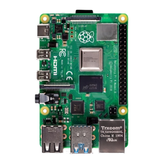
2.4. Powering a Raspberry Pi CANdle can be used to power custom 5V devices such development boards. This allows customers to leverage the power control and monitoring features of CANdle when using a Raspberry Pi subsystem. Do not connect or -V to the load. -
Page 12: Controlling A Single-Color Led
1/17/2022 2.5. Controlling a single-color LED Single-color non-addressable LED strips that simply take direct voltage are also supported with CANdle. These LEDs are not individually addressable – meaning all LEDs will increase with brightness as the output intensifies. For such LEDs, connect to the LEDs. -
Page 13: Pixel Pulse Train Control - Separate Controller
However, CANdle can also auto-detect a WS2812B-compliant pulse-train from common generators such as the Arduino. No software configuration is required by CANdle for this, simply wire CANH to the pulse-train signal, and CANL to the logic ground of the signal generator. -
Page 14: Daisy Chain From Single Power Source
CANdle User’s Guide www.ctr-electronics.com 1/17/2022 2.7. Daisy Chain from Single Power Source Additionally, a supplemental CANdle can be powered “down-stream” of another CANdle. Note that this will increase the current draw of the “up-stream” CANdle. Cross The Road Electronics Page 14... -
Page 15: Control Methods
Individually addressable LEDs can also be controlled by a WS2812B-compliant pulse-train. Connect the pulse train signal to CANH (yellow) and connect the signal generator’s ground reference to CANL (green). The CANdle will still provide power to the downstream LEDs, allowing system developers to only be concerned about color control. -
Page 16: Mounting
The CANdle can be mounted using the provided spacers. This allows clearance for the wires to travel out under the heatsink. This is a particularly convenient method of mounting the CANdle, as it only requires a flat surface to drill holes into and subsequently mount against. -
Page 17: Panel Mounting
CANdle User’s Guide www.ctr-electronics.com 1/17/2022 4.2. Panel Mounting CANdle can also be panel mounted. This requires milling out a hole so that the front face (LED side) can be fitted through. Refer to Section 8 for mechanical dimensions. Cross The Road Electronics... -
Page 18: External Led Strip Types
If requesting a solid color produces several colors to appear on the LEDs, then the LED strip likely uses 32 bit pixels (with separate white component) whereas CANdle is configured for three colors (no white component) or vice versa. Cross The Road Electronics... -
Page 19: Phoenix Tuner / Phoenix Framework
CANdle User’s Guide www.ctr-electronics.com 1/17/2022 6. Phoenix Tuner / Phoenix Framework Like all CAN bus devices from CTR-Electronics, CANdle is supported in Phoenix Framework. CANdle is supported in Phoenix Tuner. This allows for fast and efficient debugging of your robot platform... -
Page 20: Faq
7.4. Is the CANdle an LED strip or LED controller? The CANdle is both an LED strip and an LED controller. The first eight addressable LEDs are onboard and integrated. The first extern LED added via the wire leads is considered the “ninth” addressable LED. This will be references as index ‘8’ in software. -
Page 21: Mechanical Drawings
CANdle User’s Guide www.ctr-electronics.com 1/17/2022 8. Mechanical Drawings Cross The Road Electronics Page 21 1/17/2022... -
Page 22: Revision History
CANdle User’s Guide www.ctr-electronics.com 1/17/2022 9. Revision History Revision Date Description 17-Jan-2022 Initial Creation. Cross The Road Electronics Page 22 1/17/2022...
Need help?
Do you have a question about the CANdle and is the answer not in the manual?
Questions and answers