Fröling SPS 4000 Operating Instructions Manual
Boiler controller
Hide thumbs
Also See for SPS 4000:
- Service manual (144 pages) ,
- Operating instructions manual (212 pages)
Table of Contents
Advertisement
Quick Links
Operating Instructions
Boiler controller SPS 4000
Version 01.06
Translation of the original German operating instructions for technicians
Read and follow the instructions and safety information!
Technical changes, typographical errors and omissions reserved!
B0960417_en | Edition 16/02/2018
Fröling GesmbH | A-4710 Grieskirchen, Industriestraße 12 | www.froeling.com
Advertisement
Table of Contents

Subscribe to Our Youtube Channel
Related Manuals for Fröling SPS 4000


Summary of Contents for Fröling SPS 4000
- Page 1 Operating Instructions Boiler controller SPS 4000 Version 01.06 Translation of the original German operating instructions for technicians Read and follow the instructions and safety information! Technical changes, typographical errors and omissions reserved! B0960417_en | Edition 16/02/2018 Fröling GesmbH | A-4710 Grieskirchen, Industriestraße 12 | www.froeling.com...
-
Page 2: Table Of Contents
Table of Contents 4.5 Perform hardware detection manually 1 General 4.6 Configuring the boiler 1.1 Safety information 4.6.1 Setting the boiler type 4.6.2 Setting the boiler-specific parameters 2 Electric components and wiring List of possible parameters 2.1 SPS 4.7 Configure fuel feed 2.1.1 Display 4.7.1 Chamber discharge system Ports and displays... - Page 3 6.6.9 Backup 6.2.16 External boiler control Save configuration 6.2.17 Control parameters Load configuration 6.6.10 Specification values 6.3 Fuel feed Boiler specifications 6.3.1 Stoker Fuel specifications Own templates 6.3.2 Feed screw/feeder Factory setting 6.3.3 Hopper Operating Instructions SPS 4000 | B0960417_en...
- Page 4 7.1 Fault handling 8.1.4 Performing a software update 8.1.5 Connecting to the SPS with PC 7.2 Fault message list Connection via a local network (LAN) Direct connection to SPS 4000 8 Appendix SPS 4000 network settings PC network settings 8.1 FAQ 8.1.6 System Diagnostic Manager (SDM)
-
Page 5: General
Subject to technical change. About these instructions The range of functions of the SPS 4000 depends on the user level currently set. These instructions show all the parameters that are available with full functionality in the "Service" user level (maximum configuration with all possible system components). -
Page 6: Safety Information
General Safety information 1.1 Safety information DANGER When working on electrical components: Risk of electrocution! When work is carried out on electrical components: ❒ Only have work carried out by a qualified electrician ❒ Observe the applicable standards and regulations ➥... -
Page 7: Electric Components And Wiring
Electric components and wiring 2 Electric components and wiring 2.1 SPS The controller consists of two main components. The CPU/display unit and the input/output rack. In addition, the frequency converters are connected to the controller by modbus. Operating Instructions SPS 4000 | B0960417_en... -
Page 8: Display
Electric components and wiring 2.1.1 Display Power Panel PP65, 5.7" QVGA colour TFT display with touch screen (resistive), 128 MByte DRAM, 232 kByte SRAM, CompactFlash slot, Ethernet 10/100, 1x X2X link, 2x USB, protection class IP65 (front) Ports and displays Power supply Ethernet port (RJ45 shielded, transfer rate 10/100 MBit/s) Two USB ports (type A, USB 1.1, USB 2.0) - Page 9 33 dec (33 / 16 -> 2 + 1 remainder) = 21 hex (x16 = 2, x1 = 1) e.g. 180 dec (180/16 -> 11 + 4 remainder) = B4 hex (x16 = B, x1 = 4) Operating Instructions SPS 4000 | B0960417_en...
-
Page 10: Changing The Compact Flash
Electric components and wiring Status displays The following status LEDs are below the node number switches: Colour Status Description Status Error/reset Orange Boot / ready mode User Green On/off LED being operated by the application Orange The module is sending data via the X2X interface Orange Access to the Compact Flash medium Changing the Compact Flash... -
Page 11: Replacing The Battery
➥ Only handle the battery by the faces ➥ When inserting the battery, ensure that the ribbon for removing it again is correctly positioned ❒ Replace the battery cover and switch on the power supply Operating Instructions SPS 4000 | B0960417_en... -
Page 12: X20 - Module Layout
Electric components and wiring 2.1.2 X20 – module layout The X20 input/output rack is a modular system, consisting of several modules, which in turn are made up of three components. Bus module Electronic module Terminal block Assembling the module Top view Front view ❒... - Page 13 ❒ Position the electronic modules beside the bus module as shown and push in until they engage ❒ Hook the terminal block onto the electronic module ❒ Push the terminal block into the electronic module until it engages Operating Instructions SPS 4000 | B0960417_en...
- Page 14 Electric components and wiring Fitting the modules to the top hat rail Top hat rail lever unlocked Top hat rail lever locked (module fixed to top hat rail) (module can be removed) ❒ Tilt up the top rail lever of all modules in the rack ❒...
-
Page 15: X20 Module Types
▪ Input voltage for X2X link supply too low Red illuminated (e) Incorrect firmware Green flashing (r) Orange No communication at X2X link Communication at X2X link OK X2X link supply OK Power supply unit overloaded (additional supply modules required) Operating Instructions SPS 4000 | B0960417_en... - Page 16 Electric components and wiring NOTICE! Connection 1-5 does not have to be wired as there is an internal jumper between terminal 1-4 and terminal 1-5. The connection diagram below shows how the module is wired: Wire jumper for supplying the X2X link Fröling GesmbH | A-4710 Grieskirchen, Industriestraße 12 | www.froeling.com...
-
Page 17: Ps2100
No error / no supply to module Double flashing LED indicates one of the following operating statuses: ▪ I/O supply too low ▪ Input voltage for X2X link supply too low Red illuminated (e) Incorrect firmware Green flashing (r) Operating Instructions SPS 4000 | B0960417_en... - Page 18 Electric components and wiring For this module, you will need to decide whether it is to be used as an additional supply or as a separate feed from the rest (e.g. to create interlocking voltages). It is mainly used with the SPS4000 to create interlocking voltages.
- Page 19 A PS2100 module needs to be inserted here to supply the subsequent inputs/outputs with 24V up to point 3. This setup could, for example, be a locking unit. A PS2100 module is inserted again here to supply the remaining inputs/outputs with 24V. This setup could, for example, be another locking unit. Operating Instructions SPS 4000 | B0960417_en...
-
Page 20: Bt9100
Electric components and wiring BT9100 The BT9100 is a bus transmitter module and is used to seamlessly expand the X20 system. The stations can be up to 100 metres apart. NOTICE! The bus transmitter module must only be operated with the BM11 bus module! If the feed for the internal I/O supply is used, this potential group must not be powered by any other module. - Page 21 The connection diagram below shows how the module is wired without a feed for the internal I/O power supply: The connection diagram below shows how the module is wired with a feed for the internal I/O power supply: Operating Instructions SPS 4000 | B0960417_en...
-
Page 22: Cs1012
Electric components and wiring CS1012 Module for use as an M-Bus master. Heat meters approved by Froling can be read out on the M-Bus. Colour Status Description Green Not in operation (no power supply) Single Flash Unlink mode Double flash Boot mode (during firmware update) Flashing Preoperative mode... - Page 23 Electric components and wiring CS1012 The connection diagram below shows how the module is wired: NOTICE! The maximum permissible line resistance (longest loop) is 250Ω. The maximum permissible line capacitance for the entire bus is 500 nF. Operating Instructions SPS 4000 | B0960417_en...
-
Page 24: Cs1030
Electric components and wiring CS1030 Module for communicating with the frequency converters and for communicating in cascades and Modbus systems. A X2X link cable is required for custom assembly. ⇨ See "Cascade / Modbus" [page 54] Colour Status Description Green Not in operation (no power supply) Quick flashes Reset mode... -
Page 25: Di2377
Quick flashes Reset mode Flashing Preoperative mode Module in operation No error / no supply to module Red illuminated (e) Incorrect firmware Green flashing (r) 1 - 2 Green Input status of the corresponding input Operating Instructions SPS 4000 | B0960417_en... -
Page 26: Di9371
Electric components and wiring DI9371 Module with twelve digital inputs. The inputs feature sink wiring and 1 line terminal. Colour Status Description Green Not in operation (no power supply) Quick flashes Reset mode Flashing Preoperative mode Module in operation No error / no supply to module Red illuminated (e) Incorrect firmware Green flashing (r) - Page 27 Electric components and wiring The connection diagram below shows how the module is wired: Operating Instructions SPS 4000 | B0960417_en...
-
Page 28: Do9322
Electric components and wiring DO9322 Module with twelve digital outputs. The outputs feature source wiring and 1 line terminal. Colour Status Description Green Not in operation (no power supply) Quick flashes Reset mode Flashing Preoperative mode Module in operation No error / no supply to module Quick flashes Warning/error at an output. - Page 29 Electric components and wiring Operating Instructions SPS 4000 | B0960417_en...
-
Page 30: Do8332
Electric components and wiring DO8332 Module with eight outputs. The outputs feature source wiring and 1 wire technology. Maximum rated output current 2A Colour Status Description Green Not in operation (no power supply) Single Flash Reset mode Flashing Preoperative mode Module in operation No error / no supply to module Single Flash... - Page 31 Electric components and wiring The connection diagram below shows how the module is wired: Operating Instructions SPS 4000 | B0960417_en...
-
Page 32: Do6639
Electric components and wiring DO6639 Module with six relay outputs (230 VAC / 2 A). The outputs are normally open and isolated as single channels. Colour Status Description Green Not in operation (no power supply) Single Flash Reset mode Flashing Preoperative mode Module in operation No error / no supply to module... - Page 33 Electric components and wiring Operating Instructions SPS 4000 | B0960417_en...
-
Page 34: Do2633
Electric components and wiring DO2633 The module has 2 Triac outputs (2x phase control), 2/3 line terminal. The power supply (L and N) are fed directly to the module. NOTICE! This module must only be used with a BM32 bus module. Colour Status Description... - Page 35 Electric components and wiring The connection diagram below shows how the module is wired in two-wire technique: The connection diagram below shows how the module is wired in three-wire technique: Operating Instructions SPS 4000 | B0960417_en...
-
Page 36: Ai4622
Electric components and wiring AI4622 Module with four analogue inputs. Colour Status Description Green Not in operation (no power supply) Quick flashes Reset mode Flashing Preoperative mode Module in operation No error / no supply to module Error or reset status Red illuminated (e) Incorrect firmware Green flashing (r) - Page 37 Electric components and wiring The connection diagram below shows how the module is wired: Operating Instructions SPS 4000 | B0960417_en...
-
Page 38: Ai4222
Electric components and wiring AI4222 Module with four analogue inputs. Colour Status Description Green Not in operation (no power supply) Quick flashes Reset mode Flashing Preoperative mode Module in operation No error / no supply to module Error or reset status Red illuminated (e) Incorrect firmware Green flashing (r) - Page 39 Electric components and wiring The connection diagram below shows how the module is wired: Operating Instructions SPS 4000 | B0960417_en...
-
Page 40: Ao4622
Electric components and wiring AO4622 Module with four analogue outputs. Colour Status Description Green Not in operation (no power supply) Quick flashes Reset mode Flashing Preoperative mode Module in operation No error / no supply to module Error or reset status Red illuminated (e) Incorrect firmware Green flashing (r) - Page 41 Electric components and wiring The connection diagram below shows how the module is wired: Operating Instructions SPS 4000 | B0960417_en...
-
Page 42: Ao2622
Electric components and wiring AO2622 Module with two analogue outputs. Colour Status Description Green Not in operation (no power supply) Quick flashes Reset mode Double flash Modbus BOOT (during firmware update) Flashing Preoperative mode Module in operation No error / no supply to module Error or reset status Red illuminated (e) / Green flashing (r) Incorrect firmware... - Page 43 Electric components and wiring The connection diagram below shows how the module is wired: Operating Instructions SPS 4000 | B0960417_en...
-
Page 44: At6402
Electric components and wiring AT6402 Module with six temperature inputs for thermocouples (e.g. flue gas temperature sensor, combustion chamber sensor). Colour Status Description Green Not in operation (no power supply) Quick flashes Reset mode Flashing Preoperative mode Module in operation No error / no supply to module Error or reset status Single Flash... - Page 45 Electric components and wiring For type K thermocouples, the following applies: Plus (+) = green, minus (-) = white Operating Instructions SPS 4000 | B0960417_en...
-
Page 46: At4222
Electric components and wiring AT4222 Module with four temperature inputs for the measurement of PT100 and PT1000 sensors (e.g. boiler temperature sensor, store sensor,...). Colour Status Description Green Not in operation (no power supply) Quick flashes Reset mode Flashing Preoperative mode Module in operation No error / no supply to module Error or reset status... - Page 47 The left-hand side shows the connection of a 3-wire sensor. On the right-hand side, the connection of a 2-wire sensor is shown according to the 3-wire principle. In this case, the second and third terminals (both minus poles) are connected (bridged) directly on the field terminal. Operating Instructions SPS 4000 | B0960417_en...
-
Page 48: Sensor Characteristic Line Pt100
Electric components and wiring Sensor characteristic line PT100 2.2 Sensor characteristic line PT100 The table below shows the resistance [Ω] of the temperature sensor at a certain temperature. The temperature in a table cell is determined by the start temperature of the line plus the value of the column: Fröling GesmbH | A-4710 Grieskirchen, Industriestraße 12 | www.froeling.com... -
Page 49: Sensor Characteristic Line Type K
The table below shows the thermoelectric voltage [mV] of the temperature sensor at the specified temperature difference. The temperature in a table cell is determined by the start temperature of the line plus the value of the column: Operating Instructions SPS 4000 | B0960417_en... - Page 50 Electric components and wiring Sensor characteristic line type K Fröling GesmbH | A-4710 Grieskirchen, Industriestraße 12 | www.froeling.com...
-
Page 51: Frequency Converter
Up arrow Scroll down through groups and parameters. Increase/reduce the value of a flashing digit Down arrow Enter Go forward one step in the program menu. Save a change to a parameter value Operating Instructions SPS 4000 | B0960417_en... -
Page 52: Changing Parameters
Electric components and wiring Frequency converter 2.4.2 Changing parameters Step Description Connecting the power supply 3x escape until “0.0” appears in the display The group menu letter flashes when you press the Enter button Press the arrow buttons to select the relevant group menu (d,P,t,C,A) Enter the previously selected group menu. - Page 53 You can restore the factory settings by setting parameter P 112 to 1. The parameter then automatically returns to the value 0 and the frequency converter displays the message "F048". Operating Instructions SPS 4000 | B0960417_en...
-
Page 54: Cascade / Modbus
Electric components and wiring Cascade / Modbus 2.5 Cascade / Modbus The CS1030 communication module must be used for cabling in a cascade or for integration into a ModBus system. ⇨ See "CS1030" [page 24] In addition, the following wiring diagrams and connection instructions must be observed. Wiring the cascade When wiring the cascade, make sure that the terminating resistor is activated for the communication module on the master boiler and the last slave boiler. - Page 55 In addition, a terminating resistor must be ensured by the higher-level system. Superordinate Modbus system (Terminating resistor 120 Ohm) Data - Data + Terminating Terminating Terminating Terminating resistor ON resistor OFF resistor OFF resistor ON Operating Instructions SPS 4000 | B0960417_en...
-
Page 56: Terminating Resistor At Communication Module
The CS1012 communication module must be used for cabling the M-bus (meter bus). ⇨ See "CS1012" [page 22] A maximum of three heat meters can be evaluated on the SPS 4000. There are no specific limitations for cabling the M-bus. User can be connected in either a star or line structure. -
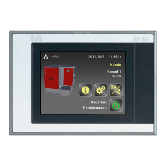
Page 57: Overview Of The Basic Functions
System menu icon for opening the system settings. All parameters can be displayed/edited depending on the user level Quick menu icon for viewing the available quick functions Info menu icon for viewing all system information Mode icon for switching the boiler on/off Mode display Operating status display Operating Instructions SPS 4000 | B0960417_en... -
Page 58: Control Icons
Overview of the basic functions Control icons 3.2 Control icons Cancel icon Discards any values entered without saving and closes messages. Confirm icon Confirms any values entered and activates parameters. Home icon Tapping the Home icon takes you back to the basic display from any menu. Info menu icon To access all system information. -
Page 59: Initial Startup
➥ After the system start of the controller, the boiler type is set to the default “Turbomat TM 150” and the SPS hardware is not configured ❒ Before setting the boiler type, perform a software update and start the hardware detection Operating Instructions SPS 4000 | B0960417_en... -
Page 60: Changing The Language
Initial startup Changing the language 4.3 Changing the language ❒ Tap the quick select icon on the start screen ❒ Use the left and right arrows to navigate to the language icon ❒ Open the language selection by tapping the language icon ❒... -
Page 61: Performing A Software Update
❒ Connect the USB stick with the update information to the USB interface of the SPS ❒ Go to the “Software” menu System menu Software ❒ Tap the update icon to start the procedure ➥ The controller will now restart several times Operating Instructions SPS 4000 | B0960417_en... -
Page 62: Perform Hardware Detection Manually
4.5 Perform hardware detection manually Automatic hardware detection is performed after a software update or a cold start of the SPS 4000. In case of an error or to perform a check, this procedure can also be done manually. The detection is carried out in four steps;... - Page 63 ➥ Configuration file is written to the system directory and the SPS restarts ❒ After the SPS has restarted, open the "Hardware list" menu from the start screen and check that the list of components found is correct. Operating Instructions SPS 4000 | B0960417_en...
-
Page 64: Configuring The Boiler
Initial startup Configuring the boiler 4.6 Configuring the boiler Once you have successfully updated the software and completed the hardware configuration, you need to set the boiler type and boiler-specific parameters: 4.6.1 Setting the boiler type To set the boiler type, go to the corresponding “Boiler type" menu: System menu System Boiler type... -
Page 65: Setting The Boiler-Specific Parameters
Joint ash removal installed? Specifies if there is a joint ash line section for multiple boilers. If the parameter is set to “Yes”, joint ash removal with ash removal for the boiler is activated. Operating Instructions SPS 4000 | B0960417_en... - Page 66 Initial startup Configuring the boiler Grate type Number of secondary air flaps Number of tertiary air flaps Specifies which grate design Only used as an indicator and depends on boiler type and is installed in the boiler and output. how the grate is operated. For boilers with retort Control of combustion air fan combustion, set the...
-
Page 67: Configure Fuel Feed
The following chamber discharge systems are available: Standard rotary agitator, pellet screw Separately powered rotary agitator Sliding floor / Sliding floor, controlled externally Oblique screw / Oblique screw, Horizontal screw / Horizontal screw, Suction system controlled externally controlled externally Operating Instructions SPS 4000 | B0960417_en... -
Page 68: Fuel Feed: General Information
Initial startup Configure fuel feed Sliding floor with interchangeable Chamber discharge system, controlled externally with/without container level container As for the sliding floor, the control is in Use with chamber discharge systems without setting the exact type. Request is a fuel store. However, to activate the made via a switch contact on the SPS. - Page 69 Specifies if a hopper is used in the feed system to the boiler. Hopper Burn back protection system Back burn slide valve / cross feeder Burn back flap Coupled rotary valve Separate rotary valve Rotary valve, coupled + separate 2x separate rotary valve Operating Instructions SPS 4000 | B0960417_en...
-
Page 70: Configure Hydraulic System
Initial startup Configure hydraulic system Determine maximum fuel feed-in above grate differential pressure Prerequisite: The required differential pressure transmitter must be installed on the boiler! Activates the calculation of the fuel infeed quantity by evaluating the differential pressure above the combustion grate. -
Page 71: Sample Configuration
Initial startup Configure hydraulic system 4.8.1 Sample configuration Operating Instructions SPS 4000 | B0960417_en... - Page 72 Initial startup Configure hydraulic system Procedure for configuring the sample hydraulic system In the “System menu” => “System configuration” => “Hydraulic system”: ❒ Number of additional distributors: 4 ❒ Number of storage tanks: 4 ❒ Number of heating circuits: 8 ❒...
-
Page 73: Configure Additional System Options
Specifies if a flue gas heat exchanger is used with regard line. to using the energy in the flue gas. Filter type Spark trap installed Specifies if a filter is used and defines the design of the Specifies if spark trap is used. filter. Operating Instructions SPS 4000 | B0960417_en... -
Page 74: I/O Configuration
Initial startup I/O configuration 4.10 I/O configuration During the I/O configuration the parameters for inputs and outputs are assigned to the ports of the I/O cards in the SPS rack. Please refer to the section entitled “Electrical connection and wiring" for instructions on how to connect and a description of the different card types. - Page 75 The speed of the units controlled by the phase angle modules is monitored by the counter inputs of the same name. 3. Duplicate assignment Duplicate assignment of the outputs is not permitted! Duplicate assignment of inputs is possible and required on a case-by-case basis. Operating Instructions SPS 4000 | B0960417_en...
-
Page 76: I/O Configuration According To Circuit
The system-specific circuit diagram which has been used for wiring the system components is stored in the control cabinet of the boiler. All the necessary information for the configuration of the individual inputs and outputs of the SPS 4000 are shown in the circuit diagram. Example: Digital output for boiler loading pump ❒... -
Page 77: Setting The Parameters Of The Frequency Converter
➥ If fuel is visible on the edge of the ejection area in the gravity shaft, the discharge screw(s) is (are) completely filled with fuel ➥ If no fuel is visible, the manual operation function must be restarted Operating Instructions SPS 4000 | B0960417_en... - Page 78 Initial startup Performing the first start / Checking the settings Step 3 – Start the boiler / Check parameter settings ❒ Switch the boiler on by tapping “Boiler ON” ➥ If a request is pending, the boiler starts and runs through the following operating statuses up to the heating status: - Preparation - Fill stoker...
-
Page 79: Operation
The system menu shows the menu items available depending on the user level and the system configuration. Tap the icon to open the corresponding menu item. The system menu is structured in a circular buffer, which can be navigated using the right and left arrows. Operating Instructions SPS 4000 | B0960417_en... -
Page 80: Navigating Within Submenus
Operation Navigation within the system menu 5.2.1 Navigating within submenus After you open a menu item, the corresponding status display with current values will appear. If, for example, several heating circuits are installed, you can use the right and left arrows to navigate to the desired heating circuit. -
Page 81: Displaying/Changing Parameters
It is only possible to view or edit parameter details if there is a pen icon beside the parameter value: ❒ Tap the relevant parameter ➥ The detailed view of the parameter will open Operating Instructions SPS 4000 | B0960417_en... -
Page 82: Displaying Parameter Info
Operation Displaying/changing parameters Parameter name Displays the changed value Current parameter value setting. Parameter is reset to this value if you cancel the entry Specified values for quick selection of standard, minimum and maximum (equals the setting range for the parameter) 5.3.1 Displaying parameter info ❒... -
Page 83: Changing The Parameter Value
❒ You can also tap “Minimum", “Default" or “Maximum" to set to the respective value displayed below ❒ Tap the confirm icon to save the set value ➥ The parameter value is saved and the setting dialogue closes Operating Instructions SPS 4000 | B0960417_en... - Page 84 Operation Displaying/changing parameters Entering a value If a numeric keypad icon appears beside the parameter value in the display field, you can enter the value directly: ❒ Tap the numeric keypad icon ➥ The Enter values window for parameters will appear ❒...
-
Page 85: Quick Menu
➥ The unit will be regulated to the value specification set in the respective menu ➥ The function will remain active until the process is ended by tapping "Auto" or the Manual switch menu is closed Operating Instructions SPS 4000 | B0960417_en... -
Page 86: Setting The Date And Time
Operation Setting the date and time 5.6 Setting the date and time ❒ Tap the date and time area on the start screen ➥ The menu for setting the date and time will appear ❒ Tap the relevant value to change it ❒... -
Page 87: Setting Times
❒ Set the start and end time for the time window using the up and down arrows ➥ The hours and minutes are set separately for each time ❒ Apply the set time window by tapping the confirm icon Operating Instructions SPS 4000 | B0960417_en... -
Page 88: Applying The Time Setting For Several Days
Operation Setting times 5.7.1 Applying the time setting for several days The heating times set for a certain day can be applied to other days: ❒ Use the left or right arrow to navigate to the day of the week with the desired heating times ❒... -
Page 89: Switching User Level
❒ Open the input field for the user code by tapping the User level icon ❒ Enter the user code using the numeric keypad and confirm by tapping the confirm icon ➥ The functions in the selected user level are available Operating Instructions SPS 4000 | B0960417_en... -
Page 90: Menus And Parameters
Menus and parameters Heating circuits & system 6 Menus and parameters 6.1 Heating circuits & system 6.1.1 Backup boiler / Swivel burner Backup boiler – Configuration System menu Heating circuits & Backup boiler system Backup boiler 1 name Release backup boiler 2 depending on storage tank minimum Freely definable name of backup boiler. -
Page 91: Swivel Burner - Configuration
If the startup criteria is fulfilled for this duration, Swivel burner: 0% demand during storage tank loading the second stage of the oil burner is activated. Storage tank charge at which the oil burner is requested with 0%. Operating Instructions SPS 4000 | B0960417_en... -
Page 92: Cascade
Menus and parameters Heating circuits & system 6.1.2 Cascade Cascade - Temperatures System menu Heating circuits & Cascade system 0% power demand stage 1 during power requirement 0% power demand stage 3 during power requirement 0% power demand stage 1 during power requirement. 0% power demand stage 3 during power requirement. -
Page 93: Cascade - Configuration
Use lime injection? Repeat reminder after days If the “lime deficiency" warning has been acknowledged, it is activated again after the time set here if the lime deficiency has not been rectified in the meantime. Operating Instructions SPS 4000 | B0960417_en... -
Page 94: Configuration For Flue Gas Heat Exchanger
Menus and parameters Heating circuits & system Configuration for flue gas heat exchanger System menu Heating circuits & Flue gas Flue gas system treatment Max. runtime of FGHE bypass flap FGHE cleaning interval If the FGHE bypass flap could not be moved within this Operating time of FGHE after which cleaning should take time, a fault is issued. -
Page 95: Hydraulics: General Information
Active with DHW tank 1 Active with DHW tank 4 The running performance of the feeder pump depends on the respective DHW tank and is switched on and off in parallel with the DHW loading pump. Operating Instructions SPS 4000 | B0960417_en... -
Page 96: Boiler Distributor
Menus and parameters Heating circuits & system Hysteresis Speed control based on return temperature Prerequisite: The “Use temperature sensor” Specifies if the speed of the feeder pump should be dependent on a return sensor. If this parameter is active, parameter must be active the associated setting parameters (return temperature Defines the temperature hysteresis for switching off the setpoint, minimum and maximum speed) are displayed. -
Page 97: Assigned Components
Adjustment of the minimum speed to the pump type. (Set tank from which the boiler loading pumps are released. the pump mode according to pump manufacturer’s The value applies for all DHW tanks assigned to the instructions) distributor. Operating Instructions SPS 4000 | B0960417_en... -
Page 98: Assigned Components
Menus and parameters Heating circuits & system Maximum distributor pump speed Distributor pump 1 - 4 Kp Prerequisite: Distributor without storage tank. Defines the gain factor of the PI controller. The higher the value is set, the more sensitive the controller reacts. The speed control of the distributor pump is limited by this value (e.g. -
Page 99: Heating Circuits - Times
Calculated flow temperatures, which according to the set heating curve are higher, are reduced to this value. Heating circuits - Times System menu Heating circuits Heating circuits & system ⇨ See "Setting times" [page 87] Operating Instructions SPS 4000 | B0960417_en... -
Page 100: Heating Circuits - Configuration
Menus and parameters Heating circuits & system Heating circuits - Configuration System menu Heating circuits Heating circuits & system Name heating circuit 1 Heating circuit mixer Kp Freely selectable name for this heating circuit. A maximum Specifies the gain of the stepped controller for the heating of 32 characters can be used for the description. -
Page 101: Dhw Tank - Times
Menus and parameters Heating circuits & system DHW tank - Times System menu Heating circuits DHW tank & system ⇨ See "Setting times" [page 87] Operating Instructions SPS 4000 | B0960417_en... -
Page 102: Dhw Tank - Configuration
Menus and parameters Heating circuits & system DHW tank - Configuration System menu Heating circuits DHW tank & system Name of DHW tank 1 Legionella heating start time Freely selectable name for this DHW tank. A maximum of Specifies the time at which the DHW tank starts to heat up 32 characters can be used for the description. -
Page 103: Storage Tank
If the storage tank temperature falls below this value by the set hysteresis, the heating circuit controller is Operating Instructions SPS 4000 | B0960417_en... - Page 104 Menus and parameters Heating circuits & system Heating circuit release from top storage tank temperature Storage tank loading when outdoor temperature +10°C stopped. Defines the required storage tank charge in percent when the external temperature is -10°C. The Lambdatronic DHW tank release from storage tank top temperature calculates the current storage tank charge setpoint in conjunction with the “storage tank loading at +10°C”...
-
Page 105: Buffer Tank - Times
Storage tank delay Setting for whether storage tank management should be Specifies the delay time in seconds, when the internal used with more than two sensors. storage tank demand changes from 0 to 100%. Operating Instructions SPS 4000 | B0960417_en... -
Page 106: Boiler
Menus and parameters Boiler 6.2 Boiler 6.2.1 Mode System menu Boiler Mode Boiler mode ▪ Cascade: To activate cascade mode. This mode is only available if the boiler is set as the master or slave The current operation mode of the boiler is shown under boiler. -
Page 107: Boiler Settings
Above the set value, the boiler operates in nominal load. Temperature rise in return feed for start of quick regulation The quick regulation responds to this temperature increase within the set monitoring time. Operating Instructions SPS 4000 | B0960417_en... -
Page 108: Water Temperatures
Menus and parameters Boiler 6.2.4 Water temperatures System menu Boiler Water temperatures Pumps start at Minimum boiler temperature setpoint Specifies the boiler temperature in °C from which the boiler Minimum setting value of the boiler temperature setpoint. loading pump and the heating circuit pumps can be switched on by the controller. - Page 109 Boiler pump manual operation return setpoint value. The parameter applies exclusively Defines the speed of the boiler pump in case of manual activation in the "Manual operation" menu. Operating Instructions SPS 4000 | B0960417_en...
-
Page 110: Ignite
Menus and parameters Boiler 6.2.5 Ignite System menu Boiler Ignition Infeed time without ignition Maximum temperature drop during heating During this time the boiler attempts to go to “heating” If the CCT decreases by this value when heating starts, status by feeding material without activating the ignition. If the ignition fan is activated again. -
Page 111: Air Flaps/Blower Fan
If the combustion chamber temperature reaches the start value of the CCT Operating Instructions SPS 4000 | B0960417_en... - Page 112 Menus and parameters Boiler Secondary air delay Speed monitor delay Specifies the time delay for the secondary air in seconds. The speed is only monitored (startup) after the delay has 67% of the required air flap position is reached within this elapsed period.
- Page 113 Air flap secondary1 stop 100% opening If the value is above this, the flap is detected as being open. Due to tolerances in the return signal, an open flap may return an opening of just under 100%. Operating Instructions SPS 4000 | B0960417_en...
-
Page 114: Frequency Converter
Menus and parameters Boiler Frequency converter System menu Boiler Air flap blower fan ID fan nominal motor voltage (P101) Combustion air nominal motor voltage (P101) Nominal voltage of motor according to identification plate. Nominal voltage of motor according to identification plate. ID fan nominal motor frequency (P102) Combustion air nominal motor frequency (P102) ID fan nominal motor current (P103) -
Page 115: Test
“safety time expired" error will appear temperature” parameter -> "100% power at flue gas after a safety time (“safety time” parameter). temperature” parameter). This prevents the cold fire clay from heating up too quickly. Operating Instructions SPS 4000 | B0960417_en... -
Page 116: Combustion Chamber
Menus and parameters Boiler Ignition power at flue gas temperature No infeed below residual oxygen content Specifies the flue gas temperature that must be reached, If the residual oxygen content falls below this value, infeed so that power can be increased. Below this temperature is stopped. - Page 117 FGR system reduces the infeed when the combustion Reduce output combustion chamber temperature 2 Kp chamber temperatures are too high. Reduce output combustion chamber temperature 2 Tn Reduce output combustion chamber temperature 2 Tn Operating Instructions SPS 4000 | B0960417_en...
-
Page 118: Heat Exchanger Cleaning
Menus and parameters Boiler 6.2.9 Heat exchanger cleaning System menu Boiler cleaning Heat exchanger cleaning activated from Heat exchanger cleaning interval Starting point of the time window during which the heat Specifies how long the feed screw must feed until the exchanger cleaner (WOS or compressed air) can switch WOS drive is activated (“heat exchanger cleaning runtime"... -
Page 119: Fgr
Defines the maximum opening of the FGR primary air flap and serves to limit the proportion of FGR primary air. Residual oxygen reduction in FGR mode Specifies the maximum reduction to the residual oxygen content in percent that can be made FGR mode. Operating Instructions SPS 4000 | B0960417_en... - Page 120 Menus and parameters Boiler Max. reduction of primary air in FGR mode FGR secondary air delay Specifies the amount by which the primary air (fresh air) Specifies the time delay for the FGR secondary air in can be reduced at maximum FGR primary air. Please note seconds.
-
Page 121: Frequency Converter
Manual grate control extended so that it does not fall short of this time. Manual specification of grate activation Operating Instructions SPS 4000 | B0960417_en... -
Page 122: Ash Removal
Menus and parameters Boiler Grate running during heating up Duration of infeed reduction when max. temp. under grate exceeded When activated the grate is also active during heating up. Time the boiler delivers minimum output to cool the grate Max. time grate to end position Duration till shutdown when max. -
Page 123: Joint Ash Removal
When the temperature in the slide-on duct rises by the set value, a warning message appears on the display. When the criteria for switching off is reached, the slide-on duct cooling continues to remain active for the set time. Operating Instructions SPS 4000 | B0960417_en... -
Page 124: Special Mode
Menus and parameters Boiler 6.2.15 Special mode System menu Boiler Spec. operation Extra heating duration Relative reduction of primary air during chimney sweep mode The time set here specifies how long Extra Heating lasts. Relative reduction of primary air (FGR and fresh air) in Extra heating minimum runtime chimney sweep mode from the current setpoint value specification. -
Page 125: Control Parameters
(similar to winter mode). Please note that the parameter should be Boiler-Tn disabled again after the measurement has been carried out (= set to “0”) Reset time of the PI controller for the boiler controller Operating Instructions SPS 4000 | B0960417_en... -
Page 126: Fuel Feed
Menus and parameters Fuel feed 6.3 Fuel feed 6.3.1 Stoker System menu Fuel Stoker feed Stoker filling time Delay overfilling rotary value 2 This is the time the empty stoker screw requires to feed The time by which an error message is delayed when the material from the gravity shaft to the combustion chamber. -
Page 127: Feed Screw/Feeder
Operating Instructions SPS 4000 | B0960417_en... - Page 128 Menus and parameters Fuel feed Feed screw runtime automatic run Feeder shutdown delay Specifies how long the discharge or oblique screw is If the level sensor in the gravity shaft detects material for switched on in override. this time period, the special feeder is stopped. With the cross feeder the current stroke can be ended and the cross feeder can be returned to the end position Feed screw 2 always active?
-
Page 129: Hopper
Hopper rotary agitator runtime in % Refill hopper timeout The hopper rotary agitator runtime equals this percentage If the hopper is not filled within this period of time, an error interval value. is triggered. Operating Instructions SPS 4000 | B0960417_en... -
Page 130: Chamber Discharge System
Menus and parameters Fuel feed 6.3.4 Chamber discharge system System menu Fuel Chamber feed discharge system Rotary agitator operating mode Oblique screw time for change of direction Operating mode of rotary agitator. Time from oblique screw discharge until change of direction of rotation Rotary agitator runtime at interval Oblique screw return according to overcurrent... -
Page 131: Sliding Floor
Sliding floor automatic run runtime Specifies how long the sliding floor is activated for in override. Operating Instructions SPS 4000 | B0960417_en... -
Page 132: Suction System
Menus and parameters Fuel feed 6.3.6 Suction system System menu Fuel Suction system feed Minimum time for empty status detection Cyclone 1 Cyclone 1 active Suction turbine run-on Cyclone is active Run-on time of suction turbine, if cyclone full. Cyclone 1 loaded with Vibration available? ▪... -
Page 133: Rotary Valves
Delay error overfilling rotary valve 1 after chamber Delay error overfilling rotary valve 2 after chamber discharge system discharge system Delay error overfilling rotary valve 1 after chamber Delay error overfilling rotary valve 2 after chamber discharge system discharge system Operating Instructions SPS 4000 | B0960417_en... -
Page 134: Plc
Menus and parameters 6.4 PLC 6.4.1 Software System menu Software Displays the current software version and execution of software updates Performing a software update 6.4.2 Connections Network Shows the current status and offers an opportunity to reset in the event of connection problems: ❒... -
Page 135: Field Bus
Field bus Modbus cascade Modbus cascade socket Modbus cascade slave ID Socket of the modbus card used for the cascade Unique slave identification in cascade network communication M-bus System menu Connections Field bus M-bus Operating Instructions SPS 4000 | B0960417_en... - Page 136 Menus and parameters NOTICE! Menu is only displayed if the associated interface Heat meter 1 address card CS1012 was detected. Heat meter 2 address Number of heat meters Heat meter 3 address Specifies how many heat meters are to be read. The Defines a unique address for the respective heat meter.
-
Page 137: Display
Backlight switched off if no entries are made during this time. Calibrate touchscreen System menu Control system Touchscreen Calibrate Calibrate touchscreen touchscreen NOTICE Inaccurate calibration! If you do not tap the indicated points accurately, the control may stop working properly Operating Instructions SPS 4000 | B0960417_en... -
Page 138: Hardware
Menus and parameters 6.4.4 Hardware System menu Control system Hardware ⇨ See "Perform hardware detection manually" [page 62] 6.4.5 SPS restart System menu Control system SPS restart Restart control (hot start) Restart and re-initialise control (cold start) The control is restarted but the current status is saved. The control is restarted and reinitialised After the restart After the control has restarted, the previously set status is the boiler is in boiler OFF status. -
Page 139: Diagnosis
If all 250 entries are in use and there is another fault message entry, the oldest entry in the list is overwritten. Operating Instructions SPS 4000 | B0960417_en... -
Page 140: Clear Error
Menus and parameters Diagnosis Clear error System menu Diagnosis Error Current faults Acknowledge and clear all errors Tapping the icon deletes all messages in the fault log 6.5.2 Inputs and outputs System menu Diagnosis Inputs and outputs Digital inputs Temperature inputs PT 100 Used to test the digital inputs and intended only for service Used to test the temperature inputs for PT100 sensors and technicians. -
Page 141: System
External error messages for this time are suppressed on Defines the text of the freely assignable message shown startup, in order to give the remote station also enough on the display. time to be able to start. Operating Instructions SPS 4000 | B0960417_en... -
Page 142: Diagnostic Data
Menus and parameters Diagnosis Message 1/2/3 type Message 1/2/3 delay Defines the type of message that affects the behaviour of Defines the delay in seconds until the message is the boiler. triggered after the event occurs. ▪ Info: Message is displayed only once ▪... -
Page 143: Usb Recording Configuration
The “Current value” menu shows all system-specific values. The number of values depends on the specified boiler type and the configured components in the boiler system. 6.5.8 Operating times System menu Diagnosis Operating times Boiler ON since Boiler active since Operating Instructions SPS 4000 | B0960417_en... - Page 144 Menus and parameters Diagnosis Boiler HEATING since Fröling GesmbH | A-4710 Grieskirchen, Industriestraße 12 | www.froeling.com...
-
Page 145: System Configuration
Heating circuit “Heating circuit 4” associated to Heating circuit “Heating circuit 8” associated to To which heat distribution nodes is the heating circuit To which heat distribution nodes is the heating circuit associated? associated? Operating Instructions SPS 4000 | B0960417_en... -
Page 146: Dhw Tank
Menus and parameters System configuration DHW tank System menu System Heating circuits DHW tank configuration & system DHW tank “DHW tank 1” associated to DHW tank “DHW tank 3” associated to To which heat distribution nodes is the DHW tank To which heat distribution nodes is the DHW tank associated? associated? -
Page 147: Backup Boiler
Flue gas configuration & system treatment Multicyclone installed? Flue gas heat exchanger installed? Multicyclone installed? Flue gas heat exchanger installed? Filter type Spark trap installed? What type of filter is used? Spark trap installed? Operating Instructions SPS 4000 | B0960417_en... -
Page 148: Pumps
Menus and parameters System configuration Pumps System menu System Heating circuits Pumps configuration & system - general Number of feeder pumps Number of feeder pumps used. 6.6.3 Boiler type System menu System Boiler type configuration Boiler type Boiler type 6.6.4 Boiler System menu System Boiler... -
Page 149: Fuel Feed
Star-delta switching time Discharge type ▪ Screw: pellet screw, jointly powered rotary agitator, rotary agitator with separate rotary agitator drive, sliding floor with cross feeder screw Stoker type ▪ Hydraulic conveyor Stoker screw or hydraulic stoker Operating Instructions SPS 4000 | B0960417_en... -
Page 150: Inputs And Outputs
Menus and parameters System configuration Discharge type Number of chamber discharge system rotary valves ▪ Raking chain / band Number of chamber discharge system rotary valves Number of feed screws Determine maximum fuel feed-in above grate differential pressure Number of feed screws Determine maximum fuel feed-in above grate differential Hoppers installed? pressure... -
Page 151: Operating Times
Defines the boiler number according to identification plate. Automatic user logout System name Return to customer operating level if no entries are made Freely definable system name. Maximum 32 characters. during this time. Name / Company First name Operating Instructions SPS 4000 | B0960417_en... -
Page 152: Backup
Menus and parameters System configuration 6.6.9 Backup NOTICE! There are two USB ports available, which can be used simultaneously. However, only one USB storage device may be connected at a time! Save configuration System menu System Backup Save configuration configuration Save error log to file This function is used to save the system configuration. -
Page 153: Specification Values
In this menu, specified fuel values can be saved and loaded. Load template ❒ Select template ❒ Tapping the icon accepts the specifications for the selected fuel Save / Manage templates The service code must be entered to manage or save current settings! Operating Instructions SPS 4000 | B0960417_en... -
Page 154: Factory Setting
Set all parameters to factory default Set all parameters and configurations to factory default (Urinit) Tap the icon to reset the SPS 4000 to the factory default settings. All the settings for the boiler and the boiler system, as well as the customer-specific parameters will be lost. -
Page 155: Troubleshooting
Troubleshooting Fault handling 7 Troubleshooting 7.1 Fault handling Fault Preparation Pre-heat phase Fire present Heating Empty stoker run-on Restart cleaning run-on Operating Instructions SPS 4000 | B0960417_en... -
Page 156: Fault Message List
Troubleshooting Fault message list 7.2 Fault message list Error text An internal error has occurred. Please check log. A system error has occurred. Please check log. Control restarted by reset Power failure XXX Initialisation error parameter. Battery dead Read error parameter. Write error parameter. - Page 157 The motor protection of the combustion chamber ash screw 2 has activated. The thermal contact of the combustion chamber ash screw has activated The thermal contact of the heat exchanger ash screw has activated The thermal contact of the grate motor has activated Operating Instructions SPS 4000 | B0960417_en...
- Page 158 Troubleshooting Fault message list Error text Lambda probe faulty Excess pressure in combustion chamber Ignition attempt unsuccessful - Check combustion chamber and ignition Fire safety time expired -> fire has gone out Combustion chamber temperature too low for too long during heating, check sensor! Flue gas temperature too low for too long during heating, check sensor! Boiler sensor fault Boiler return temperature not OK...
- Page 159 Primary air flap error Secondary air flap 1 timeout Secondary air flap 1 error Secondary air flap 2 timeout Secondary air flap 2 error Tertiary air flap 1 timeout Tertiary air flap 1 error Operating Instructions SPS 4000 | B0960417_en...
- Page 160 Troubleshooting Fault message list Error text Tertiary air flap 2 timeout Tertiary air flap 2 error Primary air flap FGR timeout Primary air flap FGR error Secondary air flap FGR timeout Secondary air flap FGR error FGR flap timeout Air vane timeout Boiler ventilation timeout - the set temperature was not reached Low combustion chamber temperature reached, cleaning possible The safety switch of the combustion chamber ash box has activated...
- Page 161 Unable to close filter cutoff flap Filter cleaning timeout Filter fault Lime deficiency filter: Please check fill level of limestone container Rotary valve filter fault Ash box filter not connected Filter cleaning compressed air fault Operating Instructions SPS 4000 | B0960417_en...
- Page 162 Troubleshooting Fault message list Error text Spark trap not active Spark trap: Alarm 1, spark trap activated Spark trap: Alarm 2, too many sparks Spark trap malfunction Filter limestone feed fault Chimney sweep mode terminated due to filter (bypass or fault) Filter not active Casing cooling bypass flap not configured.
- Page 163 The gravity shaft of the joint ash removal is open. The ash container of the joint ash removal is not connected. External fault with the joint ash removal. Fault with the joint ash removal. Operating Instructions SPS 4000 | B0960417_en...
- Page 164 Troubleshooting Fault message list Error text The motor protection switch of feed screw 5 has activated. Feed screw 5 overcurrent Feed screw 5 level switch timeout The motor protection switch of feed screw 6 has activated. Feed screw 6 overcurrent Feed screw 6 level switch timeout Cyclone 1 suction system timeout Cyclone 1 gate valve timeout...
- Page 165 Ground fault at FGR frequency converter (Error XXX) Error in the supply to the frequency converter (Error XXX) General error at FGR frequency converter (Error XXX) Communication problem with FGR frequency converter (Error code XXX). Check MODBUS settings. Operating Instructions SPS 4000 | B0960417_en...
- Page 166 Troubleshooting Fault message list Error text Parameter XXX at FGR frequency converter outside of permitted FC limits (Error code XXX). Error in the connection to the FGR frequency converter (Error code XXX). FGR frequency converter not ready. Overload at combustion air frequency converter (Error XXX) Short circuit at combustion air frequency converter (Error XXX) Ground fault at combustion air frequency converter (Error XXX) Error in the supply to the combustion air frequency converter (Error XXX)
- Page 167 The temperature sensor ‘Storage tank 3 sensor 4’ is not connected / incorrectly connected or defective. The temperature sensor ‘Storage tank 3 sensor 5’ is not connected / incorrectly connected or defective. The temperature sensor ‘Storage tank 3 sensor 6’ is not connected / incorrectly connected or defective. Operating Instructions SPS 4000 | B0960417_en...
- Page 168 Troubleshooting Fault message list Error text The temperature sensor ‘Storage tank 3 sensor 7’ is not connected / incorrectly connected or defective. The temperature sensor ‘Storage tank 3 sensor 8’ is not connected / incorrectly connected or defective. The temperature sensor ‘Storage tank 3 sensor 9’ is not connected / incorrectly connected or defective. The temperature sensor ‘Storage tank 3 sensor 10’...
- Page 169 The temperature sensor ‘Storage tank 5 sensor bottom’ is not connected / incorrectly connected or defective. The temperature sensor ‘Storage tank 6 sensor top’ is not connected / incorrectly connected or defective. The temperature sensor ‘Storage tank 6 sensor bottom’ is not connected / incorrectly connected or defective. Operating Instructions SPS 4000 | B0960417_en...
-
Page 170: Appendix
None of the PT100 store sensors are connected any more using a Rinck element; instead they are connected directly to the SPS 4000. There is no longer an analysis via averager, as all temperatures can be read off directly on the SPS 4000. -
Page 171: Lambda Probe 0-10V
Appendix Lambda probe 0-10V The residual oxygen is measured on the SPS 4000 using the broadband probe and the 0-10V signal of the sensor box. Operating Instructions SPS 4000 | B0960417_en... -
Page 172: Boiler Program (Start-Shut Down)
Appendix 8.1.2 Boiler program (Start-shut down) The diagram below illustrates a possible boiler program sequence without the occurrence of a fault: FIRE DETECTED Standby For fire to be detected the following must apply: ▪ the minimum combustion chamber temperature has been reached ▪... -
Page 173: Back Up/Restore Memory Card
The installation package is available as a compressed file “PVI_4.2.4.102_CD.zip”. ❒ Extract the installation package to any folder ❒ Go to that folder and run "Install.exe" ❒ Select the relevant language on the start screen Operating Instructions SPS 4000 | B0960417_en... - Page 174 Appendix ❒ In the menu tree on the left, select "PVI Development" ❒ Click “Start installation" to run ➥ Follow the instructions of the installation wizard ➥ Once the software has been successfully installed, "B&R Automation" will appear in the start menu Step 2 - Runtime Utility Center ❒...
- Page 175 ❒ To back up and restore memory cards, click the third menu item “Create / restore a drive image" ❒ Insert the CompactFlash card into the relevant slot in the computer or use an appropriate card reader Operating Instructions SPS 4000 | B0960417_en...
- Page 176 Appendix ❒ Click the “Update” button to browse the available drives ❒ Select the drive with the memory card from the dropdown menu and confirm Fröling GesmbH | A-4710 Grieskirchen, Industriestraße 12 | www.froeling.com...
- Page 177 ➥ For better traceability, the filename should contain the name of the system/customer and the current date ➥ When creating the name, do not use any spaces, full stops or special characters (underscores "_" are allowed) ➥ The special data format "zp2" must not be changed Operating Instructions SPS 4000 | B0960417_en...
- Page 178 Appendix ❒ Confirm current file settings with “Save" The process can take some time depending on the amount of data. The progress bar shows the current status while the image file is being created. Once the backup has been created, a message appears stating that the process has been successfully completed Step 4 - Restore memory card Once again, the memory card must be recognised and correctly assigned.
- Page 179 ❒ If you do not want to delete the data on the memory card, you can cancel the process here ❒ To start, confirm the warning message with “Yes" ➥ All the data on partitions on the memory card will be deleted and overwritten with the backup data Operating Instructions SPS 4000 | B0960417_en...
-
Page 180: Performing A Software Update
Appendix 8.1.4 Performing a software update Requirements for a software update: ▪ Froling-approved USB stick (max. 2GB!) ▪ Update .zip file ❒ Open the update file (.zip file) saved on the computer ➥ Zip file contains a folder, an .xml file and the version information as a .txt file ❒... - Page 181 Appendix ❒ Following the update, check the software version on the “System” tab in the info menu Operating Instructions SPS 4000 | B0960417_en...
-
Page 182: Connecting To The Sps With Pc
8.1.5 Connecting to the SPS with PC A PC connection to the SPS 4000 is required for the data exchange via the Froling visualisation software or for analysis via the System Diagnostic Manager. For a connection to the SPS 4000, the Ethernet interface integrated on the back of the display is used. -
Page 183: Direct Connection To Sps 4000
If the system is not integrated into a local area network, the PC is connected directly to the Ethernet interface of the SPS 4000 with a cross-over cable. A cross-over cable is used for direct connections between two network- compatible devices. The difference compared to a conventional network cable is that the signals for sending and receiving data are crossed. -
Page 184: Sps 4000 Network Settings
DHCP switched on If the DHCP function is activated on the SPS 4000, the network settings are automatically retrieved from the server/router and the system integrated in the local network. ADVANTAGE: There must be no incorrect network settings present, for example, a duplicate assignment of a network address. - Page 185 DISADVANTAGE: If the boiler is integrated in a local network, the settings on the SPS 4000 must be checked in the event of a change and adjusted, if necessary. If there are several devices on your network with manual setting of the IP address, there is the risk of incorrect network settings through a duplicate assignment.
-
Page 186: Pc Network Settings
255.255.0.0 gives a maximum of 65,534 usable IP addresses). Importantly, unlike the IP address the subnet mask must be the same in the respective network for all devices. For the manual assignment of the subnet mask to the SPS 4000, DHCP must be deactivated. ⇨ See "DHCP settings" [page 184] ❒... - Page 187 ➥ The properties window for the LAN connection will open ❒ In the properties window, select the "Internet protocol (TCP/IP)" element and click on "Properties" ➥ The properties for the internet protocol (TCP/IP) will appear Operating Instructions SPS 4000 | B0960417_en...
- Page 188 A gateway is a kind of transition point from one network to the other (e.g. Internet). In most local networks the default gateway is usually the IP address of the router. For the data exchange between PC and SPS 4000 within the local network or with direct connections, the default gateway is not required.
- Page 189 ➥ The properties window for the LAN connection will open ❒ In the properties window, select "Internet protocol version 4 (TCP/IPv4)" and click on "Properties" ➥ The properties for the internet protocol (TCP/IP) will appear Operating Instructions SPS 4000 | B0960417_en...
- Page 190 A gateway is a kind of transition point from one network to the other (e.g. Internet). In most local networks the default gateway is usually the IP address of the router. For the data exchange between PC and SPS 4000 within the local network or with direct connections, the default gateway is not required.
-
Page 191: System Diagnostic Manager (Sdm)
⇨ See "Connecting to the SPS with PC" [page 182] ❒ Open Internet browser (Microsoft Internet Explorer, Mozilla Firefox, Google Chrome, ...) ❒ In the address line of your internet browser enter the network address of the SPS 4000 followed by “/sdm” (for example: 192.168.0.1/sdm) ➥... -
Page 192: Saving Log File To Data Medium
Appendix Saving log file to data medium ❒ In the navigation area select the "Logger" category ❒ Select the desired logger module and click on "Upload from target" ➥ The window for saving the logger file is displayed. ❒ Select the desired directory and start the save process by clicking on “OK” Fröling GesmbH | A-4710 Grieskirchen, Industriestraße 12 | www.froeling.com... -
Page 193: Create System Dump
❒ Select menu item “Parameters + Data Files” and continue with “OK” ➥ Confirm the security prompt ❒ To save the data, select the function “Upload form target”, select the desired directory and start the save process Operating Instructions SPS 4000 | B0960417_en... -
Page 194: Addresses
Appendix Addresses 8.2 Addresses 8.2.1 Address of manufacturer FRÖLING Heizkessel- und Behälterbau GesmbH Industriestraße 12 A-4710 Grieskirchen AUSTRIA TEL 0043 (0)7248 606 0 FAX 0043 (0)7248 606 600 EMAIL info@froeling.com INTERNET www.froeling.com Customer service Austria 0043 (0)7248 606 7000 Germany 0049 (0)89 927 926 400 Worldwide 0043 (0)7248 606 0...
Need help?
Do you have a question about the SPS 4000 and is the answer not in the manual?
Questions and answers