
Summary of Contents for PRECITEC CHRocodile CLS0.2
- Page 1 CHRocodile CLS Optical line sensor for non-contact distance and thickness measurement Operation Manual...
- Page 2 It may not be reproduced or used in a manner contrary to the company’s legal interests without prior written approval of Precitec Optronik GmbH. It is strictly intended for use in the context of service operations. Any other use is impermissible. Any sharing of this documentation with third parties requires the prior, expressed written approval of Precitec Optronik GmbH.
- Page 3 Version Control Version – Date Type of Change Manual 1.0.0.0 2014/01/29 Original edition 1.0.0.1 2014/03/13 Updated Mechanical plans and specifications 1.0.0.2 2014/05/12 Auto Reference procedure 1.0.0.3 2014/05/22 Specifications correction 1.0.0.4 2014/09/09 EMC compatibility + Jumbo packet + Medical or safety-relevant usage 1.0.0.5 2014/11/06 Ethernet connection + Status LED + Optical head specifications Optical head specifications + Sync In additional information + CLS...
-
Page 4: Table Of Contents
Table of Contents Table of Contents ......................4 Basic Safety Instructions ....................8 Warranty and Liability ..................8 Safety Symbols ....................8 Proper Use ......................9 Duty of Operator and Personnel ..............10 Safety Measurements in Normal Operation ........... 10 Protection from Electronic Shock .................. - Page 5 2.6.2 Power supply jack ........................20 2.6.3 USB port RS232 serial communication................... 21 2.6.4 Ethernet connector ......................... 21 2.6.5 Encoder-input .......................... 21 2.6.6 Trigger Input/Output / RS422 serial communication ............22 Status LED ..........................24 2.6.7 Sensor Characteristics ..................25 2.7.1 Sensor unit characteristics .....................
- Page 6 Detailed Commands Description ..............43 5.2.1 DNLD Command ........................43 ETR Command ........................43 5.2.2 IPCN Command ........................44 5.2.3 LAI Command........................45 5.2.4 NOP Command ........................46 5.2.5 5.2.6 SCA Command ........................47 5.2.7 SHZ Command ........................48 5.2.8 SODX Command ........................
- Page 7 Distance Measurement: ................... 71 Thickness measurement: ................72 Technical support ......................74...
-
Page 8: Basic Safety Instructions
Precitec Optronik GmbH apply to all of our products. We reserve the right to make any changes to the device’s construction for reasons of improving quality or expanding the possible applications as well as any made for production-related reasons. -
Page 9: Proper Use
ARNING Do not touch – indicates that touching the contact/optics surface can cause damage/destruction of the component. MPORTANT Information which the user must pay attention to/ be aware of in order to avoid disruptions in the course of processing/ in product use. Provides information that the user needs in order to achieve the intended result of an action most directly and without difficulty. -
Page 10: Duty Of Operator And Personnel
use the original devices and replacement parts and observe the instructions for EMC-compliant installation in the handbooks that come with them. If the optical sensor is operated inside a facility with other devices, the entire facility must comply with the provisions in the EC-Guidelines in the demands of the general operating permit. -
Page 11: Grounding The Device
do not look directly into the LED’s light. The light can harm your eyes. 1.5.3 Grounding the device Make sure that the device is grounded in compliance with regulations. Please make sure that the optical sensor is supplied with power via a grounded main power input line (cold device plug). -
Page 12: Product Description
PRECITEC is the first company to propose a confocal chromatic device, with all elements embedded in one Optoelectronic unit (no apparent optical cables) in order to adapt to industrial changing requirement. -
Page 13: Measuring Principle
2.2 Measuring principle 2.2.1 Optical principle For most industrial applications the chromatically coded distance detection method turned out to be very well suited. CHRocodile CLS is based on this method and more precisely on the Confocal Chromatic principle. This principle combines the properties of confocality and axial chromatism. Axial Chromatism: That method takes advantage from a lens optical error commonly known as axial chromatic aberration: the axial position of the focal point depends on the wavelength (color) of the light to be focused. -
Page 14: Principle Applied To Multiple Points Sensor
Fig. 2-2: Chromatic Confocal Imaging principle (point sensor) 2.2.2 Principle applied to multiple points sensor Applying Confocal Chromatic Imaging to multipoint sensor consists in increasing the number of illumination point’s source and the number of pinhole in front of the detector spectrometer. In this configuration, the spectrometer is preferably bidimensionnal. -
Page 15: Sensor Functionalities
2.3 Sensor Functionalities The CHRocodile CLS has two different measuring mode: Distance and Thickness measurement. The principle of these two measuring mode are explained hereafter. Mode 1 Chromatic Distance Measurement Topographic, profile or roughness measurements are performed in Mode 1 (confocal distance measurement). In this process, 192 points along a white light line are focused on the surface of the measured object using an optic with a known chromatic aberration. - Page 16 Mode 2 Chromatic Thickness Measurement Thickness measurements are performed in Mode 2 (confocal thickness measurement). If a transparent material is within the measurement volume of the Chromatic Optical Head, 192 points along a white light line are focused on both the two surfaces of the measured object. The reflected light is more intense for the two wavelengths in focus on the two surfaces.
-
Page 17: Typical Applications (Overview)
It could be used both on various reflecting and scattering surfaces. The PRECITEC confocal chromatic line sensor is very well adapted to industrial environment, as no optical cable are connected to the CHRocodile CLS unit. The absence of optical cables, promotes robustness and compactness of the measuring device, and also facilitates the integration and use on a motorized moving system, such as a coordinate measuring machine (CMM). -
Page 18: List Of Deliverables
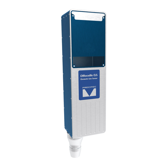
2.5 List of Deliverables One operational Confocal Chromatic Line Sensor unit (see Fig. 2-6), One operational Optical Head (see Fig. 2-7), One set of electric cables (power supply) (see Fig. 2-8), Power Supply Adapter (100-240V to 24V +/-10%) (see Fig. 2-8), A CD with DLL and firmware, Software user guide, Operation Manual,... - Page 19 Fig 2-6: CHRocodile CLS unit 3D view: a- Straight version b- Right angled version Fig 2-7: Optical Head 3D view: a- CLS0.2 b- CLS1 c- CLS2.3 d- CLS4 Fig 2-8: Set of electrical cables: a- Power supply b- Adapter...
-
Page 20: Connections And Interfaces
2.6 Connections and Interfaces All of the connection ports for the sensor unit are located at the rear of the system (see Fig 2-9): 1. ON / OFF Switch button, 5. Encoder-Input, Sub-D26 male connector 2. Power supply jack 6. Trigger Input/Output + RS422, Sub-D15 female 3. -
Page 21: Usb Port Rs232 Serial Communication
2.6.3 USB port RS232 serial communication The serial RS232 is interfaced on the USB port. Serial communication are mostly used for sending command as a hyper-terminal. As the number of channel is high with a huge amount of data, serial communication port cannot support data transfer. -
Page 22: Trigger Input/Output / Rs422 Serial Communication
Differential encoder input 120 Ohm terminated ground Differential encoder input 120 Ohm terminated Differential encoder input 120 Ohm terminated Differential encoder input 120 Ohm terminated Differential encoder input 120 Ohm terminated ground Not connected Differential encoder input with switchable 120 Ohm Differential encoder input with switchable 120 Ohm Differential encoder input with switchable 120 Ohm Differential encoder input with switchable 120 Ohm... - Page 23 Signal SyncIn SyncOut Isolated-GND [A] RS422 (CTS) [A] RS422 (RTS) [A] RS422 (RXD) [A] RS422 (TXD) Isolated-GND Isolated-GND Isolated-GND [B] RS422 (CTS) [B] RS422 (RTS) [B] RS422 (RXD) [B] RS422 (TXD) Table 2.3: Interface (pin configuration) Signal Function Description RS432 RS422 Isolated (Isolated-GND) RS422 Interface Interface...
-
Page 24: Status Led
but the edge can also be inverted by software command) on the rising edge, that means when the external pulldown transistor releases the input or when the pushpull drives to 5V. Wait for trigger – signal characteristics to Analog Out The sensor stops after the current data telegram is transmitted and goes into a standby mode. -
Page 25: Sensor Characteristics
2.7 Sensor Characteristics 2.7.1 Sensor unit characteristics Optical sensor Measuring principle Confocal Chromatic Measuring data Distance, Thickness Number of Channel Light source Dimensions (sensor unit) 391 x 100 x 114 mm (L x H x T) Weight 4 kg Data Transmission Measuring rate 100 –... -
Page 26: High Frequency Mode
2.7.2 High Frequency Mode A high frequency mode is now available. This optional mode gives access to frequencies measurements above the 2KHz nominal frequency and allows to measure up to 6KHz. Using this measurement mode has several impacts: Reduction of the measuring range based on the selected frequency, Decrease the number of transmitted data, Change the center of the measuring range depending on the frequency, Need for a DARK procedure when changing frequency. -
Page 27: Optical Heads Characteristics
2.7.3 Optical Heads characteristics Optical Head CLS0.2 CLS1 CLS2.3 CLS4 Specifications 0.96mm +/- 1.91mm +/- 1.53mm +/- 4.78mm +/- Line Length 0.01mm 0.02mm 0.02mm 0.04mm 5.3mm +/- 18.5mm +/- 15.6mm +/- 36.4mm +/- (1) (2) Working Distance 0.4mm 0.5mm 0.5mm 0.6mm Pitch along the line 5 +/- 0.05µm... -
Page 28: Optical Head Specifications Definitions
Optical Heads are interchangeable: the same CHRocodile CLS unit can store up to 5 different calibration tables corresponding to different Optical Heads. The Optical Head is totally passive, only the CHRocodile CLS unit has an internal Light Source and Electronic board which can be considered as heat and electrical sources. -
Page 29: Chrocodile Cls Performance Specifications
2.9 CHRocodile CLS performance specifications: Axial Resolution: Axial resolution corresponds to the static noise (standard deviation 1) on altitude or thickness measurements. It is an experimental specification. It is measured on 1000 continuous points along the measuring range for each channel along the line. Axial resolution as a function of object position inside measuring range is calculated for each channel along the line. - Page 30 Minimum and Maximum Measurable Thicknesses: The minimum and maximum measurable thickness specification is given for n=1.5 refractive index. It is measured on a standard sample in the center of measuring range for each channel. T=n.(D Fig 2-13: Minimum and Maximum measurable thicknesses...
-
Page 31: Operational Start Up
Operational Start up 3.1 Connections and Interfaces All of the connection ports are located at the rear of the CHRocodile CLS (Cf. section 2.6 Connections and Interfaces): the connection ports for the serial interfaces RS232/RS422 the connection for the encoder ... - Page 32 If the encoder-signals are fed through the sensor and additional other devices are connected (e.g. for axis control), the 100 Ohm termination can also be deactivated. Since the device has to be opened to do this, you should contact Precitec Optronik before beginning any work of this kind. Trigger Input/Output The trigger options make the lighting cycle externally controllable and the synchronization between e.g.
-
Page 33: Chrocodile Cls Explorer And Drivers Installations
An interface DLL allowing to interpret the standard commands of your 2-axis system (move, free run etc…). This slight DLL has to be written by the customer following interface specifications given by PRECITEC (Cf. CHRocodile_CLS_Explorer_User_Manual), A non-free license (USB key). -
Page 34: Cls Explorer Library
3.3.2 Via CHRocodile CLS DLL: DLL may be used to interface the sensor with a general-purpose user program. The CHRocodile CLS DLL is intended for .NET compatible language. A new DLL intended for C++ compatible language is now available and allows to use most of CLS functionalities. Refer to C++ DLL documentation. A CD containing the DLLs, some code examples and the operating Manual is delivered with the CHRocodile CLS. - Page 35 our products into your applications. A ClsExplorerLibrary DLL ultimate license will be available in September 2016 with the possibility to integrate sample scanning functionalities. Please refer to CLS Explorer Library Manual.
-
Page 36: Measurements Start Up
Measurements Start Up 4.1 Calibration Table The CHRocodile CLS unit can store up to 5 different calibration tables corresponding to different Optical Heads. In order to start measurement you need to download or select the calibration which correspond to the used Optical Head (Cf. section 5.2 in user manual). Calibration table consists in a Look Up Table which give the correspondence between the peak position (Barycenter data) and the Altitude data. -
Page 37: Auto Reference Procedure
Explorer version 1.0.1.1. The use of this procedure can modify the calibration of your sensor, consequently if required, this procedure must be done by PRECITEC, as a maintenance operation. 4.4 Mechanical interfacing After completing the operational startup, i.e. connecting with the power supply, proceed with initializing, then communication is ready and mechanical interfacing should be done. -
Page 38: Basic Settings Configuration
4.5 Basic Settings Configuration In order the CHRocodile CLS to be operational for startup some basic parameters should be set up. Basic setting configuration consists in selection of: • Measuring Range: The CHRocodile CLS could accept 5 calibration tables, and each calibration table corresponds to a unique Optical Head. - Page 39 Adjusting the axial position of the target in order the target is centered inside the optical sensor measuring range. To do this, one can move the optical head or the target along the optical axis. Thus, it is recommended to fix the optical head or the target on a translation plate. Adjusting the Line on the area to be measured.
- Page 40 to assign precisely each measurement points along the line and axis positions. To do so, one need to connect the incremental encoder-input. The CHRocodile CLS can manage with 5-axis Encoders.
-
Page 41: Advanced Configuration
Advanced Configuration 5.1 Commands List command arguments answer on query comments Continue (Measuring) <n>(<x>) “Dark reference” n: Index of the lowest measuring take dark reference and save to flash rate x: lowest frequency in Hz, floating point <1..3> DNLD Download spectrum. Currently for packet connections only. “Encoder Position“... - Page 42 <0 .. 15, ?> <optical probe Index> „optical probe“ index of used optical probe <32 .. 2000, ?> <x>Hz “Set sample rate in Hz”. x meaning the exact sample rate in Hz in floating point format <0..17> <0..17> <0..17> <0..17> … <0..17> (max 16 “Set output data extended”...
-
Page 43: Detailed Commands Description
5.2 Detailed Commands Description 5.2.1 DNLD Command Short description: Clients use this command to request a spectrum from the device. Since acquiring spectra can take up several sample periods, a DNLD request from the client causes the device to first respond with a DNLD response that does not contain any spectrum data. -
Page 44: Ipcn Command
5.2.3 IPCN Command Short description: This command allows to configure TCP/IP address and subnet mask. Command syntax: $IPCN <DHCP> <IPA> <IPB> <IPC> <IPC> <MA> <MB> <MC> <MD> <MTU> Command Description Client.Network.DhcpMode = true; $IPCN 1 Configured as DHCP client $IPCN <DHCP> $IPCN 0 192 168 170 2 255 255 255 0 0 Client.Network.DhcpMode = false;... -
Page 45: Lai Command
5.2.4 LAI Command Short description: This command allows to adjust LED intensity in order i.e. to remove saturation. Command syntax: $LAI <I> Param: <I> is Led intensity (0...100%) Command Description $LAI 95 Write Led intensity 95% Client.LedIntensity = 90; Response: $LAI 95[CR]ready[CR/LF]. $LAI ? Read Led Intensity float Led = Client.LedIntensity;... -
Page 46: Nop Command
5.2.5 NOP Command Short description: This command allows to set the number of peak to evaluate. WARNING: In confocal mode, if less than NOP peeks are detected, all thicknesses signals will be invalidated because peek identification is not possible. Command syntax: $NOP <I>... -
Page 47: Sca Command
5.2.6 SCA Command Short description: The command Scale allows to query of Full Scale in micrometers. A distance value of 32768 on the serial interface would mean a distance in (Full Scale) micrometers. To convert the integer distance value (d) received from the serial interface to a value in micrometers (D), use the formula: D[µm] = d[integer] / 32768 * Full Scale. -
Page 48: Shz Command
5.2.7 SHZ Command Short description: The command SHZ set sample rate in Hz It is possible with this command to realize any sample rates between 100Hz and 2000Hz. If the value is not accepted, the sensor responds with the string "not valid". Due to the nature of the internal time base, not every sample rate can be realized exactly. -
Page 49: Sodx Command
5.2.8 SODX Command Short description: Select Output Data (extended) SODX directly selects data words that will included output telegram specifying their indices. For example SODX 83, 16640, 16641 will output the sample counter, the distance and the intensity. Command syntax: $SODX [A0] [A1]…[AN] [Ax] is optional parameters Signal ID's scheme... - Page 50 Global Exposure Information: Definition: Bit 8 = 0 (Bit 8 to 15 = 0) Type: Float Command Description $SODX 64 sodx.GlobalSignalStartTime = true; StartTime (in nanoseconds) (Acquisition Format : UInt32) Response: $SODX 64[CR]ready[CR/LF]. sodx.GlobalSignalStartPositionX = true; $SODX 65 StartPositionX(X encoder position on (Acquisition Format : UInt32) beginning of exposure) Response: $SODX 65[CR]ready[CR/LF].
- Page 51 $SODX 72 sodx.GlobalSignalStopPositionZ = true; StopPositionZ(Z encoder position on (Acquisition Format : UInt32) end of exposure) Response: $SODX 72[CR]ready[CR/LF]. sodx.GlobalSignalStopPositionU = true; $SODX 73 StopPositionU(U encoder position on (Acquisition Format : UInt32) end of exposure) Response: $SODX 73[CR]ready[CR/LF]. $SODX 74 sodx.GlobalSignalStopPositionV = true;...
- Page 52 Peak Signal: Definition: Bit 8 = 1 (Bit 8 and 14 = 1) Type: For geometrical quantities like thickness or distance Integer 16bit, scaled as fraction of measurement range, without refractive index (optical thickness) Distance and thickness values are given as: d[µm] = value * $SCA[µm] / 32768.
- Page 53 Example: Command Description $SODX 28840 sodx.Altitude = true; Altitude, 2 peak sodx.AltitudePeak2 = true; Response: $SODX 28840[CR]ready[CR/LF]. sodx.AltitudePeakSignalOffset1 = eSodxPeakSignalOffset.Average;...
- Page 54 Additional information: Peak Signal Offset (Bits 0 to 2) Signal ID Offset Signal Name Remarks Peak Value Scaled peak distance PeakIntensity Intensity of peak CCDSaturation max. CCD illumination of related spectrum PeakPos CCD pixel pos PeakValue Median median of peak value (CHRocodile 2 only) PeakWidth confocal mode only: given in CCD pixels reserved...
- Page 55 Measuring Mode (Bit 9) Thickness: If bit 9 is set to 1, then the resulting value is thickness corresponding to the difference of the peak as defined in bits 3 and 4 and the next peak. This facility is used to request thicknesses directly. This difference value is not corrected for the index of refraction.
-
Page 56: Ssu Command
5.2.9 SSU Command Short description: The command SSU saves Setup Saves current setup to non-volatile memory (EEPROM). The Setup will be restored upon next power up. Command syntax: $SSU Command Description Client.SaveSetup(); $SSU Saves current setup Response: $SSU [CR]ready[CR/LF]. -
Page 57: Sta Command
5.2.10 STA Command Short description: The command STA starts serial data output This mode can be stored in the EEPROM. If stored, the CHRocodile CLS will begin immediately to output data telegrams on the next power-up Command syntax: $STA Command Description $STA Starts serial data output... -
Page 58: Sto Command
5.2.11 STO Command Short description: The command STO stops serial data output This mode can be stored in the EEPROM, so on the next power up the CHRocodile CLS will not begin to send measurement data until the output is restarted by the "STA"... -
Page 59: Thr Command
5.2.12 THR Command Short description: The command THR lets you specify an intensity threshold for the distance detection. It may be useful to specify a high threshold to reject all noise spikes during a measurement or to specify a low threshold to get a (noisy) result from very black surfaces. -
Page 60: Tre Command
5.2.13 TRE Command Short description: The command TRE is a Trigger each. Trigger each mode. Every exposure will be started by a rising edge of the sync-in-input. The exposure time of the detector is determined by the selected sample rate ($SHZ). Command syntax: $TRE Command... -
Page 61: Trg Command
5.2.14 TRG Command Short description: The command TRG is a Wait For Trigger. The command enables an exact alignment of the sensors sampling intervals with the movement of a scanning axis. It stops the sensor after completion of the current data telegram and puts it in a waiting state. This state is left by a trigger event (rising edge on the Sync in, Encoder Trigger). -
Page 62: Ver Command
5.2.15 VER Command Short description: The command VER give the Version of CHRocodile CLS. The command sends back an ASCII string which gives information on the serial number of the CHRocodile CLS (SN: ...), the DSP software (DSPsoft: ...) and the microcontroller software (C: ...). Command syntax: $VER Command... -
Page 63: Mechanical Plans
Mechanical Plans 6.1 Optical Head Mechanical plans a- CLS02 18.5 b- CLS1 36.4 c- CLS4... - Page 64 d- CLS2.3 Fig 6-1: Optical Head Mechanical plans: a- CLS0.2 b- CLS1 c- CLS4 d- CLS2.3...
-
Page 65: Chrocodile Cls Unit Mechanical Plans
CHRocodile CLS unit mechanical plans a- Straight version b- Right angled version Fig 6-2: CHRocodile sensor unit mechanical plans: a- Straight version b- Right angled version... -
Page 66: Chrocodile Cls Unit Mechanical Interface Plans
6.3 CHRocodile CLS unit mechanical interface plans Fig 6-3: Line sensor mechanical interface: Soleplate The two version of the CHRocodile CLS unit (straight version and right angled version) have a common soleplate. Consequently mechanical interfaces are the same for both versions. -
Page 67: Maintenance
Maintenance 7.1 How to change fans The goal of this document is to explain how to change the heat sink’s fans as a replacement. Inside the CHRocodile CLS, there are two fans which allow to dissipate heat induce by light source and electronic boards. - Page 68 1. Remove the 2 FHC M2 screws on the top of the box on the fan side 2. Pull the fan support. You will see some wire connected. Fig 7-13: Steps 3 to 5 3. Disconnect the two fans for an easier access 4.
-
Page 69: Optional Accessories
Fig 7-15: Steps 8 and 9 8. Connect back the fan wires to the body 9. Install back the fan support in the body. Check, and readjust the fan wire (if necessary), they still must be in the room between the 2 fans. Then fix the support with 2 FHC M2 screws. The fan replacement is done. -
Page 70: Cables
7.2.2 Cables The following list of cables are available at your PRECITEC vendor site. Sub-D-15 cables (for trigger in/out) Sub-D26 cables (for encoders input) Ethernet cables (Use shielded cable) Power supply cables... -
Page 71: Trouble Shooting
Trouble Shooting 8.1 Power off: The Status LEDs are off when the power supply cable is connected: Check the CHRocodile CLS Switch button is ON. Check the power cordon. 8.2 Communication error: No possible Ethernet communication between CLS and your computer: Check the Ethernet cable is plugged correctly in RJ45 sensor unit connector. - Page 72 Then, check and store the raw signal (this file could be demanded by PRECITEC technical support team). The raw signal should show a peak for channels which contribute to the measurement. Case 2: The target is positioned in front of the sensor, and distance measurement is valid only for some channels: Set the measuring frequency to minimum ($SHZ100 or equivalent .NET DLL function).
- Page 73 Then, check and store the raw signal (this file could be demanded by PRECITEC technical support team). The raw signal should show two peaks for channels which contribute to the measurement. Case 2: The target is positioned in front of the sensor, and thickness measurement is valid only for some channels: Set the measuring frequency to minimum ($SHZ100 or equivalent .NET DLL function).
- Page 74 Technical support Technical Support Date : CUSTOMER : PRECITEC Number: PRODUCT IDENTIFICATION Sensor Unit Serial Number : Optical Head Serial Number : Firmware Serial Number : PROBLEM IDENTIFICATION Type : Software Optic Mechanic Electronic Description : Photos: Attached files :...
Need help?
Do you have a question about the CHRocodile CLS0.2 and is the answer not in the manual?
Questions and answers