
Related Manuals for Sprog IIv4

Summary of Contents for Sprog IIv4
- Page 1 SPROG IIv4 User Guide SPROG IIv4 DCC Decoder Programmer User Guide (Also applies to SPROG IIv3) Version 1.1 April 2021 © Copyright 2021 SPROG DCC Ltd...
-
Page 2: Table Of Contents
How Many Locos Can Be Controlled? ........30 Short (one byte) Versus Extended (two byte) Addressing ..31 Using an External Booster with SPROG II ......... 32 Connecting and Using Multiple SPROG IIs ........ 33 Determining the SPROG II Firmware Version ......34 The SPROG Console .............. - Page 3 Set ZTC Mode ................37 Set Blueline Mode..............37 Unlock Firmware ................ 37 Save .................... 38 Updates to the SPROG II Firmware ..........39 Returning Your SPROG for Update ......... 39 Firmware Update Using the Bootloader ........39 Troubleshooting ................42 Useful Links ..................
-
Page 4: Introduction
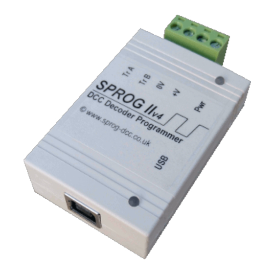
SPROG IIv4 User Guide Introduction SPROG II is a DCC decoder programmer for connection to the USB port of a personal computer or similar device. SPROG II is supported by DecoderPro and PanelPro, both part of the JMRI project (http://jmri.sourceforge.net/) which, by use of the java programming language, allows platform independent support of a wide range of DCC hardware. -
Page 5: Specification/Operating Conditions
2. SPROG II will remove track power if output current exceeds 250mA as measured 100ms after applying power. Surge current during decoder power-up may be considerably greater than this. -
Page 6: Installation
SPROG IIv4 User Guide Installation The following steps are required to install SPROG II before you can use it for the first time: Install the latest production version of JMRI (4.22 at the time of writing) Connect the Power Supply ... -
Page 7: Install The Usb Drivers (If Required)
The power LED will only illuminate steadily when power is connected to a SPROG IIv4 and the USB is connected to the host computer (next step). The power LED will only illuminate steadily when power is connected to a SPROG IIv3. -
Page 8: Setting The Jmri Connection Preferences
SPROG DCC. Then in the System connection field, select SPROG (not SPROG Command Station just yet!). This will create a connection for using the SPROG as a programmer. To use the SPROG as a command station you would select SPROG Command Station. -
Page 9: Connect The Programming Track
The programming track MUST be isolated from all other DC or DCC control systems and connected only to the SPROG II. Damage may result to the SPROG II or other equipment if this rule is not followed. Connect the SPROG II to the programming track using the “Track” terminals of the pluggable terminal block. -
Page 10: Getting Started With Decoderpro
Start DecoderPro. The main window will open and show the current connection status. In the following example “Service Mode Programmer SPROG Programmer Is Online” shows that the connection is setup to use the SPROG as a programmer, rather than a command station. In command station the Operations Mode Programmer would be available instead. - Page 11 In these cases it will be necessary to select the decoder type manually, often from several highlighted possibilities. Version 1.1 April 2021 © Copyright 2021 SPROG DCC Ltd...
- Page 12 DecoderPro once the decoder has been read or programmed. If you wish to use the Roster then you should make sure to click “Save” on the Roster Entry tab when you have finished programming the Version 1.1 April 2021 © Copyright 2021 SPROG DCC Ltd...
- Page 13 Ident button on the main DecoderPro window. Name these entries wisely! Many people use the loco type and number, or Operator/road name and number, but choose a system that will be meaningful to you. Version 1.1 April 2021 © Copyright 2021 SPROG DCC Ltd...
- Page 14 The exact look and layout of these programming panes may vary as versions of DecoderPro or the specific decoder types are updated, but the essential Version 1.1 April 2021 © Copyright 2021 SPROG DCC Ltd...
- Page 15 “Save to Roster” button. The other tabs work in a very similar way. You may find it useful to have the decoder documentation available when setting more complex or manufacturer specific features. Version 1.1 April 2021 © Copyright 2021 SPROG DCC Ltd...
- Page 16 “Constant ratio curve” will give little change in speed at low throttle settings, greater change at higher throttle. Remember to write the changes on each sheet before moving to a new one. Next, click on the “Function Map” tab. Version 1.1 April 2021 © Copyright 2021 SPROG DCC Ltd...
- Page 17 The Function Map allows you (in those decoders that support it) to control which throttle function key is mapped to each output wire or operation (e.g. sound effect) of the decoder. Version 1.1 April 2021 © Copyright 2021 SPROG DCC Ltd...
- Page 18 Clicking a Roster entry will highlight the Program button to allow the programmer to be opened again, populated with the previously save settings. Alternatively, click the Identify button and DecoderPro will try to match the Version 1.1 April 2021 © Copyright 2021 SPROG DCC Ltd...
- Page 19 SPROG IIv4 User Guide loco against one that is saved in the Roster. Version 1.1 April 2021 © Copyright 2021 SPROG DCC Ltd...
-
Page 20: Using The Decoderpro Throttle
“New Throttle” SPROG II, when used as a programmer, supports the use of one DecoderPro throttle. See “Layout Control with SPROG II” for details of how to use SPROG II as a command station with multiple throttles. When the throttle window opens, enter the loco address and click “Set”. - Page 21 The SPROG II power LED will flash when the track power is live.
-
Page 22: Measuring Loco Current
These two buttons have the same effect with SPROG II. Measuring Loco Current Loco current may be measured by using SPROG II in command station mode and using the slot monitor, see “Layout Control with SPROG II”. Version 1.1 April 2021... -
Page 23: Getting Started With Panelpro
SPROG IIv4 User Guide Getting Started With PanelPro The PanelPro tool included with JMRI allows SPROG II to be used for the control of DCC accessory decoders for point (turnout) control. The limited output voltage and current capability of SPROG II means that it is not suitable for use with accessory decoders that take power from DCC. - Page 24 To add a turnout, use the dropdown to select the type of icon to add to the panel. Version 1.1 April 2021 © Copyright 2021 SPROG DCC Ltd...
- Page 25 In the example below, a right-hand turnout has been added and moved. The pop-up menu shows the accessory address prefixed with “ST” for “SPROG Turnout”. The turnout may be rotated, disabled or removed using the same menu.
- Page 26 In the next step two straight line segments and a left hand turnout (address 2) have been added and aligned to represent the layout of a passing loop. Left clicking on a turnout icon will change the icon and send the appropriate Version 1.1 April 2021 © Copyright 2021 SPROG DCC Ltd...
- Page 27 The SPROG Console window shows the raw DCC packets that were sent to the layout. The track power must be on for any accessory commands generated from the panel to be effective.
-
Page 28: Layout Control With Sprog Ii
Layout Control with SPROG II SPROG Command Station Mode A feature in DecoderPro is the ability to use SPROG II as a command station with control of multiple locos through on screen throttles. When operating in this mode, SPROG II is no longer a service mode (programming track) programmer. - Page 29 The remainder of the slot monitor is the list of slots, at least one slot is associated with each throttle (see below). In this example, SPROG II is supplying 259mA to the layout. A loco with long address 997 is running forward at speed step 28 and a loco with short...
-
Page 30: How Many Locos Can Be Controlled
SPROG IIv4 User Guide How Many Locos Can Be Controlled? By default, sixteen slots are available, but SPROG II is not capable of powering sixteen locos without an external booster. Run each loco individually with a representative load and note the current reading. -
Page 31: Short (One Byte) Versus Extended (Two Byte) Addressing
Short (one byte) Versus Extended (two byte) Addressing In SPROG Command Station mode the allowable address ranges are: Short addresses in the range 1 – 127 Extended addresses in the range 1 – 10239 Version 1.1 April 2021... -
Page 32: Using An External Booster With Sprog Ii
SPROG IIv4 User Guide Using an External Booster with SPROG II Please consider the SPROG DCC SBOOST, a 2.5A booster that is designed specifically for use with the SPROG family of programmers. Version 1.1 April 2021 © Copyright 2021 SPROG DCC Ltd... -
Page 33: Connecting And Using Multiple Sprog Iis
(to allow locos to be driven on to it) or connected to the SPROG II programmer, not both at the same time. Never connect more than one SPROG II or a SPROG II and any other DCC booster or DC controller to the same section of track. -
Page 34: Determining The Sprog Ii Firmware Version
SPROG IIv4 User Guide Determining the SPROG II Firmware Version Select “Get SPROG Firmware Version” from the SPROG menu The SPROG firmware version will be displayed in a new window. Click “OK” to close the window. Version 1.1 April 2021... -
Page 35: The Sprog Console
SPROG IIv4 User Guide The SPROG Console The SPROG console allows optional SPROG features to be enabled and disabled. Select the SPROG Console from the SPROG menu Version 1.1 April 2021 © Copyright 2021 SPROG DCC Ltd... -
Page 36: Title Bar
The command history pane provides the same functionality as the basic Command Monitor (available on the SPROG menu) and captures commands to and replies from the SPROG. The history may be saved to a file on the computer by first choosing a log file and then selecting “Start logging”. The command history can be useful in diagnosing problems encountered in using the SPROG. -
Page 37: Selecting Sprog Operating Modes
After changing any of the following modes, you should use the “Save” button to store the changes in the SPROG. Speed Step Modes Choose the speed step mode to be used by the SPROG throttle. The default is 128 step, which is recommended for all recent DCC decoders. Current Limit Set the current limit for the SPROG track output when using a SPROG throttle, or when connected in Command Station mode. -
Page 38: Save
Always click this button after selecting a new mode. The selected modes (apart from “Unlock Firmware”) will be stored in the SPROG, so that they are effective each time you use your it, even after the power has been removed. -
Page 39: Updates To The Sprog Ii Firmware
The “firmware” is the small computer program that runs on the microprocessor at the heart of the SPROG. Occasionally it becomes necessary to update the SPROG firmware to add new features or fix bugs. The SPROG DCC philosophy is that all versions of SPROG, whether SPROG... - Page 40 SPROG IIv4 User Guide 3. Click “Save” and close the Console. 4. Select the “SPROG II/SPROG 3 Firmware Update” utility from the SPROG menu. Click “Update” if you have the new firmware file available and are ready to proceed. Click “Select hex file" and navigate to the directory where you saved the downloaded .hex file.
- Page 41 You may see a pause in activity with the message “Skip Bootloader”. This is normal, the software is skipping over (not reprogramming) the bootloader itself. When “Write Complete” is displayed, click “Set SPROG Mode”. Close the window and the firmware update is complete. Version 1.1 April 2021...
-
Page 42: Troubleshooting
Troubleshooting Before reporting any problems please check the SPROG II homepage for any bug reports or updates. There is a SPROG II FAQ page which will be updated to reflect the most common questions people have about SPROG. One common problem is the configuration of the “Virtual COM Port” for USB SPROGs. -
Page 43: Useful Links
SPROG IIv4 User Guide Useful Links SPROG homepage https://www.sprog-dcc.co.uk for the latest information, updates, downloads, etc., for SPROG II. North American distributor for SPROG II https://www.bbmgroup.com/sprog SPROG DCC group https://groups.io/g/sprog-dcc/topics for latest news and discussion of DecoderPro. Java Model railroad Interface https://www.jmri.org/...
Need help?
Do you have a question about the IIv4 and is the answer not in the manual?
Questions and answers