
Subscribe to Our Youtube Channel
Summary of Contents for RPS PRO Series
- Page 1 PRO SERIES INSTALLATION MANUAL Watch the full Watch the full Pro Series install Pro Series install video video...
- Page 2 That’s right, every single one of our customers is now successfully pumping water with an RPS system. This starts with making sure we supply you with the right pump for your land, and if issues do arise, we will immediately provide technical support and replacement parts so you can get up and pumping again as quickly as possible.
-
Page 3: Table Of Contents
USER MANUAL TABLE OF CONTENTS System Components………………………………………………… Things You Will Need…………………………………………..…… This manual System Overview..…………………………………………..……….. will... Controller Overview…………………………………………………. Mounting Solar Panels……………………………………..……… Answer your questions before you have them! Wiring Solar Panels………….……………………………………. 5HP Wiring Diagram………………………..………… Enable you to have the tools and equipment you need on the Using Existing Panels……………………………………….……. - Page 4 Be sure to ground the system for safety and to prevent damage to equipment. Remember, safety first! RPS is not liable for damage or injuries that result from improper installation technique. If you’re unsure about the safety aspects of any...
-
Page 5: System Components
NOTE: in some larger systems you may receive multiple. PRO SERIES ACCESSORY KIT— Every Pro Series kit will come with most of the accessories you need. In your accessory kit your will find: 7) Mounting & Grounding Kit 8) Pump Splice Kit 9) Tank Sensor Splice Kit 10) Electrical Tape & Teflon Tape 11) Keypad and wire for advanced use only 12) Plug connector for Pump Wires &... -
Page 6: Things You Will Need
● Solar panel mount: RPS offers 8-panel adjustable top-of-pole mount and Scalable Ground Mount kits that are compatible with 4.5”OD Schedule 40 Steel Pipe (for the 8-panel) the Scalable Ground Mount that mounts on a 2” substructure for up to 40+ panels (rpssolarpumps.com/mounting). -
Page 7: System Overview
USER MANUAL PRO TIP: RPS Systems are designed for a wide range of pump styles and sizes. At the top of each Some components are universal (like the Controller, Mounting, AC page you will see one or more colored dots, each of these... -
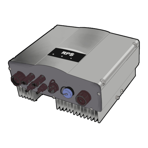
Page 8: Controller Overview
PUMP CONTROLLER OVERVIEW The RPS Pro Series Controller is the brains of your setup. This highly intelligent apparatus is pre programmed and will regulate the power coming from your panels and run your pump correctly. Each proseries controller is constructed of heavy duty metal and is water resistant. - Page 9 USER MANUAL PUMP CONTROLLER Specifications RPS22PRO RPS40PRO Pro 500, 750, 1000, 1500, 2000, 3000 Pro 5000, Pro 3000 1PH AC Conversion Compatible Systems (Well, Submersible, Irrigation, Effluent, and (Lakemakers, Well, Submersible, Irrigation, Sewage) Effluent, and Sewage) Solar Min Voltage 100VDC 200VDC Solar Max Voltage 450VDC...
-
Page 10: Mounting Solar Panels
MOUNTING YOUR SOLAR PANELS Solar panels should be mounted on a secure structure, ground mount or top of pole mount. Several ideas can be found at RPSsolarpumps.com/mounting Panels should face true South and at an angle appropriate for your latitude. If you are mounting your panels on an already built structure, try to get as close to the correct angle as possible. -
Page 11: Wiring Solar Panels
USER MANUAL WIRING YOUR SOLAR PANELS Your panels will have two MC4 connectors on the back, male and female. You will use these connectors to connect each panel as shown, as well as to connect them to the DC disconnect shut off switch. After that you will use the MC4 connectors from your DC Disconnect and connect into your controller. - Page 12 5 HP ONLY WIRING USE ALL 4 DIAGRAM CONNECTORS! Remember only use a maximum of 10 Solar Panels per pair of MC4 Connector Pairs *WIRES SHOWN RED AND BLACK FOR ILLUSTRATION PURPOSES ONLY, ACTUAL WIRES WILL BE BLACK...
-
Page 13: Using Existing Panels
USER MANUAL USING EXISTING SOLAR PANELS Are my existing solar panels compatible with RPS Solar Pumps? Example: RPS 100w “12v Panel” Solar Panel Sticker (on reverse side under junction box) Stats you’ll need from the sticker.. Total Power ( Pm, Watts ) - Page 14 40v // 40v = 40v 40v + 40v // 40v + 40v = 80v 40v +40v + 40v + 40v + 40v = 200v Rough Panel Specs Pro Series Voc Max 410V (Ideally 400v) Wired in Series 350 Watts 40 Vmp 1) Check Voc: 45v * 4 <...
-
Page 15: System Grounding
Be sure to ground the system for safety and to prevent damage to equipment. Remember, safety first! RPS is not liable for damage or injuries that result from improper installation technique. If you’re unsure about the safety aspects of any step in this... - Page 16 PUMP ASSEMBLY STEP 1 Remove the 4 nuts on the top of your pump motor. You will need a ½” wrench for this step. STEP 2 Remove the two screws on the wire protector located on the pump end. You will need a medium sized philips head screwdriver for this step.
- Page 17 USER MANUAL PUMP ASSEMBLY CONT. STEP 4 PRO TIP: To make the Run the wires from installation of the wire the pump motor up cover easier make sure the along the side of the wires lay flush along the pump end. pump end where the wire cover will go.
- Page 18 All safety rope to exit the well while preventing any debris from falling RPS pumps feature a filter screen that will prevent into the well. This can be installed last, after testing and final anything large from entering and clogging your pump.
-
Page 19: Plumbing & Safety Line
USER MANUAL PLUMBING & SAFETY LINE At this point in the process it is important to prep a few items for later steps. If you take these extra steps in preparation you will thank yourself later. Attach a safety rope through either of the two holes (or both) in the top of your Pro-Series pump. -
Page 20: Well Pump Plumbing
Your RPS Pro-Series submersible pump already has an internal Pro tip: use a socket set on the hose clamps instead of a check-valve installed, but it is recommended to install a dedicated screwdriver for a tighter fit. - Page 21 USER MANUAL EXAMPLE OF WELL HEAD PLUMBING After you install your hose barb you will need to attach your piping, but first you will need to figure out what your outlet will look like. We recommend using a well seal assembly. A WITH POLY PIPE AND WELL SEAL well seal is metal assembly with three holes on the top.
- Page 22 If your well has a very slow recharge rate, we recommend setting the pump as far as you can below the static water level (Pro series submersible pumps can be placed a maximum of 500ft below the water level).
- Page 23 USER MANUAL SUBMERSIBLE PLUMBING WITH POLY PIPE Outlet “T” Well Seal Male to Male threaded Coupler nipple Hose barb Hose clamps (covered by Poly Pipe electrical (actual tape) length will vary based on well depth) Hose Barb Electrical wire and Pump safety rope, taped every...
-
Page 24: Dewatering Plumbing
DEWATERING PLUMBING... -
Page 25: Booster Plumbing
USER MANUAL GB BOOSTER PLUMBING OPTIONS 1) Off the base of a surface tank (Positive pressure) Inlet Outlet 2) Using a Foot Valve and Suction from a tank * GB Booster Pumps are untraditional in that their inlet is in the common location of the outlet of most surface pumps. -
Page 26: Surface Irrigation Plumbing
SURFACE PUMP PLUMBING OPTIONS 1) Off the base of a surface tank - positive pressure makes priming Outlet easier Inlet Priming Screw 2) Using a Foot Valve * Be sure to prime and Suction from a tank pump fully before startup and prevent pump from deadheading or... -
Page 27: Priming Surface Pumps
USER MANUAL SURFACE PUMP INSTALL ** ALWAYS ** • Allow adequate space POSITIVE PRESSURE PRIMING for servicing and (Example: Above Ground Tank) ventilation. Protect the 1. Loosen Priming Screw unit from weather and 2. Create positive pressure in supply line to push water into water damage due to pump inlet or fill line with water rain or flooding or... -
Page 28: Pro Controller Wiring
WIRING YOUR PRO CONTROLLER Once your pump is assembled, it is time to set up your Pro controller. The back of your Pro-series controller has the following connections. An easy-to-connect pump wire port, an optional tank full sensor port, a keyboard input port, a standard set (or two sets for 5hp controllers) of MC4 solar panel connectors, and an AC backup port which can be connected to grid power or a generator for... - Page 29 USER MANUAL PUMP WIRING & CONNECTIONS STEP 1 You will need a spool of heavy duty submersible flat jacket pump wire. Remove about 6 inches of the outer black jacketing to expose the colored wiring inside, be sure to not cut through the inner wiring jackets. STEP 2 Strip both sets of wires ¼...
- Page 30 WIRING CONT. Start with the pump connector which has four terminals. NOTE: The connectors are indexed with grooves above ports 1 and 4 so they can only be inserted one way. If you are having issues inserting the connector, try rotating the connector. Start by unscrewing the base of the connector.
- Page 31 USER MANUAL WIRING CONT. STEP 1 When connecting the wires from your pump to your controller start by removing about 6 inches of the outer black jacketing of the heavy duty submersible flat jacket pump wire to expose the colored wiring inside. STEP 2 Srip the exposed colored wires ¼...
- Page 32 STEP 7 Finally when your pump wire is connected simply connect your adapter to your Pro Series pump controller! Your pump and controller are now connected!
-
Page 33: Connecting Ac Power
USER MANUAL CONNECTING THE SYSTEM TO AC POWER Your controller is capable of switching between solar power and 220v AC (Generator or Grid) automatically. This feature is optional, and most systems run exclusively on solar. You’ll be plugging into the AC Input Port on the bottom of your controller. - Page 34 Most Common Breaker Size Using Generators with RPS Systems Pump Model 220V Single Phase RPS Pro Series 500, 750, 1000, 220V Input 1500, 2000, 3000 6000W or greater recommended for Well Pumps, Surface Pumps, proper VFD functionality at full Hz.
-
Page 35: Dewatering Wiring
USER MANUAL WIRING YOUR DEWATERING PUMP The RPS Dewatering Pump is wired to the Pro controller using the wire coming off the pump. The pump wire splits into 4 colored wires: red, black, yellow, and green. Using a splice kit you can extend your pump wire if you need more length on your dewatering pump. - Page 36 WIRING BOOSTERS AND IRRIGATION The RPS Irrigation and GB Booster pumps are wired to the Pro controller using short wires and wire nuts. On the back of the pump is an access panel that can be opened with a flathead screwdriver and will reveal the wires inside.
- Page 37 USER MANUAL WIRING BOOSTERS AND IRRIGATION Open this panel On the back Of your system Grounding wire Connects to this screw...
-
Page 38: Bucket Test
DC Power STEP 4 All RPS pumps use a slow-start/ Slow-stop so the pump will begin to pump water within the next 20-30 seconds. If the pump does not begin to gush water, check the troubleshooting diagram. - Page 39 USER MANUAL CHECKLIST: Are you ready to lower your pump? Remember, DO NOT turn on the pump unless it’s completely under water! Watch at RPSsolarpumps/install You’ve read the manual and all the KEY STEPS in each section Pipe connected to pump with barb and hose clamps Length of drop pipe appropriate for setting pump.
- Page 40 Using Sensor Shut Off (Float or Pressure) When the water level in your tank rises it will lift the the Strip the outer jacket to expose the two 18 gauge float switch. Once it rises to a sufficient angle it sends wires and strip ¼”...
- Page 41 USER MANUAL Using a Float Switch for Pump Shut off on RPS Pro Series, Pro Irrigation, Pro Dewatering Tank Full Acts as an electrical signal that the tank is full Normally Open Open circuit to tell the controller to pump when float switch is hanging, and stop pumping when it is floating and circuit is closed (ie.
-
Page 42: Indicator Lights
If the fault occurs repeatedly you will need to connect your Keypad to the controller to read out the fault condition displayed on the red seven segment LED on the keypad. RPS Support Engineers can help troubleshoot in cases of repeated faults. -
Page 43: System Keypad
SHIFT button to The frequency your pump advance through the values. The various wants to run at. RPS systems run at 60HZ when there is indicator lights to the right will change to sufficient solar power. -
Page 44: How Pressure Switches Work
Connect the wire either of the terminals, ensuring they are on the same side of the OPEN = PUMP ON switch, and then connect your pigtail to the input on your Pro Series Controller. CLOSED = PUMP OFF ● Polarity of these wires does not matter. -
Page 45: Winterizing
USER MANUAL WINTERIZING / FREEZE PROTECTION RPS pumps are built to run year-round. However, if you only need to use your well pump during certain seasons, you may want to ‘winterize’ the system. To do this, simply switch the controller to OFF. If you have an adjustable mount, tilt the panels to achieve a steeper angle so snow doesn’t collect on the panels. -
Page 46: Warranty
But never fear, RPS Inc. has tens of thousands of customers across the USA who have successfully installed and, in those rare cases, troubleshoot their system with the help of RPS Inc. - Page 47 USER MANUAL TESTING/ TROUBLESHOOTING TEST 7 — CURRENT TO PUMP. Plug in keyboard, hit TEST 1 — CHECK SOLAR PANELS. May need solar shift key to cycle to the A setting. Reading should panel adjustment. Refer to ‘Tilt Angles’ in the manual for your season and latitude.
- Page 48 TROUBLESHOOTING FLOWCHART If you run into issues with your RPS Pro system don’t worry! Our engineers are available to take your call and help you get water moving. Before you get one on the phone there are some tests and checks you can do to find the root cause or obtain information the engineer may ask you to get started.
-
Page 49: Support
USER MANUAL ADDITIONAL SUPPORT Need additional help getting your system running? We’re here to help! If you're having issues getting your system pumping we have videos on each section of the setup, including a FULL pro-series install linked at For detailed videos on RPSsolarpumps.com/pro troubleshooting and a digital user manual you can share.. - Page 50 NOTES...
- Page 51 USER MANUAL NOTES...
- Page 52 RPS Solar Pumps 40250 County Rd 27 Woodland, CA, 95776 530.240.3825 Call or Text...
Need help?
Do you have a question about the PRO Series and is the answer not in the manual?
Questions and answers
What needs to be done to run the backup ac with generator?
To run the RPS Pro Series backup AC with a generator, connect the generator to the AC Input Port on the bottom of the controller. The controller can automatically switch between solar power and 220V AC power (from a generator or grid). The AC input plug has three pins: one for ground (between two alignment tabs) and two for Line 1 and Line 2. Make sure the generator provides 220V AC power.
This answer is automatically generated
What does a flashing MPPT light mean?