
Summary of Contents for Spanco RIGID ANCHOR TRACK
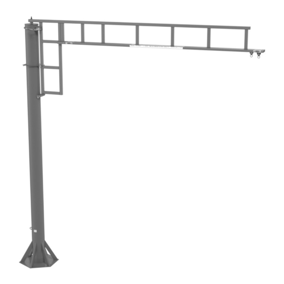
- Page 1 FREESTANDING SWING ARM ANCHOR TRACK SYSTEM ™ Assembly and Operation Instruction Manual Freestanding Swing Arm Portable Base Swing Arm ISO 9001:2015 Registered Manual 103-0070 Effective Date: March 2021...
- Page 2 RIGID LIFELINES CONDITIONS OF USE AND WARNING STATEMENT Read, understand, and follow the manual, assembly drawings, and warnings provided with your system before beginning installation. This manual, and any other instructions, must be provided to the users of this equipment. The user must understand the equipment’s proper use and limitations.
- Page 3 RIGID LIFELINES CONDITIONS OF USE AND WARNING STATEMENT 23. If supplied, all drive systems are chain driven, and as a result, will experience some backlash in the drive assembly. Although backlash cannot be fully eliminated, it can be reduced by tightening the drive chain. Torque limiters, if supplied, require special attention.
- Page 4 Follow the Inspection Checklists in this manual: review the Portable Base Swing Arm Only (Continued) first checklist before each use and the second checklist for Before moving system, use the boom lock to secure the after a fall event and annual inspections. track arm weldment to keep it from rotating.
-
Page 5: Table Of Contents
TABLE OF CONTENTS CONDITIONS OF USE AND WARNINGS STATEMENT ................i-iii SYSTEM APPLICATIONS ........................... 2 STANDARDS AND COMPLIANCE ........................2 REQUIRED TRAINING ............................2 ASSEMBLY INSTRUCTIONS ..........................3 1. Equipment Needed for Assembly ..........................2. Inventory ..................................3. Attaching the Mast Assembly to the Concrete Foundation ..................4. -
Page 6: System Applications
SYSTEM APPLICATIONS The Freestanding Swing Arm Anchor Track System is used for fall protection applications. This fall protection system is labeled ™ with maximum number of users and maximum arresting force; follow all limitations as noted on system label. Each user must attach to this system using a personal fall arrest system. -
Page 7: Assembly Instructions
ASSEMBLY INSTRUCTIONS 1. Equipment Needed for Assembly This manual b ) Applicable safety equipment for workers’ use during assembly, such as hard hats, safety shoes, etc. Telescoping fork truck or crane (minimum lifting height: 35 feet; recommended capacity: 8,000 pounds or larger depending on portable base size, if supplied) d ) Man lift/cherry picker (minimum height: 30 feet) Torque wrench... -
Page 8: Attaching The Mast Assembly To The Concrete Foundation
3. Attaching the Mast Assembly to the Concrete Foundation Refer to Freestanding Swing Arm Assembly Drawing for Steps A Through G Although there are several base plate leveling methods, this manual describes the method of using leveling nuts provided by others and grout as required on a concrete foundation. Regardless of which base plate leveling method you use, the finished installation requires full contact of the base plate on the foundation. -
Page 9: Portable Base Only: Attaching The Mast Assembly To The Foundation
4. Portable Base Only: Attaching the Mast Assembly to the Foundation Refer to Portable Base Swing Arm Assembly Drawing for Steps A Through G The finished installation requires full contact of the base plate on the foundation. All anchor bolts must have plate washers with standard clearance holes of adequate thickness for oversized base plate holes. -
Page 10: Attaching The Track Arm Weldment To The Mast
Figure 3 NOTE: Before continuing, using a Single or Top four-foot level, verify that the top Portable Base of the portable base is level both Bolt latitudinally and longitudinally on Mast Base Plate each side of the mast. Adjust the Mounting Holes Flat Washer mast and portable base as needed... -
Page 11: Attaching The Pivot Ring To The Mast And Track Arm Weldment
6. Attaching the Pivot Ring to the Mast and Track Arm Weldment Refer to Freestanding Swing Arm Assembly Drawing for Steps A Through E Per Detail “D,” insert bolts (B1) through the lined-up holes of both halves of the pivot ring (B) and securely tighten nuts (B2) to the bolts (B1) for now. - Page 12 Per Detail “A,” insert your Anchor Trolley ™ (E) into the track. For a multiple track system, install one Anchor Trolley per track. d ) Per Detail “A,” install the track’s end stops by inserting the bolts (F1) through the holes at both ends of the track arm weldment (D) and through the rubber sleeves (F2).
-
Page 13: Intermediate Bumper Installation (If Supplied)
INTERMEDIATE BUMPER INSTALLATION (IF SUPPLIED) NOTE: Follow the approval drawing, if provided, to prevent overloading of the track and system. Using a man or scissor lift, remove an end stop from the end of the track if end stop is present. Per Figure 4, slide the top plate (6) and attached components (2, 3, 4, and 5) into the track (1) and to the desired location in the track. -
Page 14: Correct System Usage And Operation
CORRECT SYSTEM USAGE AND OPERATION As shown in Figure 5, after installation, drop a plumb line from the end of the track arm weldment and rotate the swing arm 360 degrees to mark the safe and unsafe zones and obstructions. In Figure 5, one Freestanding Swing Arm Anchor Track System provides complete fall protection for almost the entire ™... -
Page 15: Maintenance
Figure 7 Never Use This System More Never Use This System Past the End Stops Than 30 Degrees Off Plumb Greater than 30 Degrees Off Plumb Incorrect Correct Incorrect Correct Per Figure 8, pull the rope down on the side of the rope closest to the locking pin to engage the boom lock assembly, if provided. -
Page 16: Labeling
LABELING The letters below correspond to the letters on the Freestanding Swing Arm Label Placement Drawing. All labeling must be legible and attached to the system. For replacement labels, contact Rigid Lifelines ® RIGID LIFELINES LABEL PLACEMENT DISCLAIMER If system is shipped unpainted or without properly secured labels, proper label placement is the sole responsibility of the end user. -
Page 17: Freestanding Swing Arm Inspection Checklists
FREESTANDING SWING ARM ANCHOR TRACK SYSTEM INSPECTION ™ CHECKLIST Before Each Use Inspector Name: __________________________________________________ Date:_____________________________________________________________ System Number: __________________________________________________ Model: ___________________________________________________________ Inspection Result (✔) INSPECTION POINTS PASS FAIL For Freestanding Swing Arm and Portable Base Swing Arm 1. Ensure that the grease fitting on top of the mast is properly lubricated. 2. -
Page 18: Annual Anchor Track ™ System
AFTER A FALL EVENT AND ANNUAL ANCHOR TRACK SYSTEM ™ INSPECTION CHECKLIST Inspector Name: __________________________________________________ Date:_____________________________________________________________ System Number: __________________________________________________ Model: ___________________________________________________________ Inspection Result (✔) INSPECTION POINTS PASS FAIL 1. Check that the beam clamps are installed horizontally within + / - five degrees. 2. -
Page 19: Product Warranty Coverage
PRODUCT WARRANTY COVERAGE Rigid Lifelines warrants its products to be free from defects in material and workmanship as follows: • Engineered Track Equipment, Wearable End Truck Wheels, and Anchor Trolley™ Wheels and Teeth: Ten Years • Motorized Products and Drive Components and Paint and Finishes for Non-Aluminum Components: Two Years •... -
Page 20: About Rigid Lifelines
ABOUT RIGID LIFELINES ® OUR MISSION: Rigid Lifelines is driven by passion for providing our customers with quality, user-friendly solutions to keep workers safer and more productive at elevation. OUR COMMITMENT Rigid Lifelines professionals are dedicated to designing and manufacturing a variety of fall protection systems that meet or exceed OSHA requirements and ANSI Z359 code.
Need help?
Do you have a question about the RIGID ANCHOR TRACK and is the answer not in the manual?
Questions and answers