Table of Contents
Advertisement
Quick Links
Advertisement
Table of Contents

Summary of Contents for SPINEA DRIVESPIN Series
- Page 1 OPERATION MANUAL FOR ELECTRIC ACTUATORS DRIVESPIN®...
-
Page 2: Table Of Contents
Table of contents General Instructions ..........................4 Documentation use ......................... 4 Structure of safety symbols ......................4 1.2.1 Interpretation of graphical symbols and marks in the document ............4 1.2.2 Safety symbols ............................ 5 1.2.3 Structure of inserted safety instructions .................... 5 Claims resulting from defects and warranty ................... - Page 3 5.2.2 Protection against overloading ......................19 5.2.3 Commissioning ..........................19 Maintenance and disposal ........................21 Maintenance ..........................22 6.1.1 Visual check ............................22 6.1.2 Cleaning ............................22 6.1.3 Maintenance schedule ........................22 6.1.4 Lubricant exchange .......................... 22 6.1.5 Disposal ............................23 Malfunction during operation .......................
-
Page 4: General Instructions
SPINEA, s.r.o. (in the following SPINEA), otherwise company SPINEA bears any liability for the consequences of their application. SPINEA is not legally liable for errors and modification of the documentation taken over from the manufacturers of electric actuator components. -
Page 5: Safety Symbols
1.2.2 Safety symbols General danger Potential of environmental threat Dangerously hot surface Danger of drag-in Magnetic field effects Risk electric shock Risk of mechanical damage Risk of injury – falling or movement at vertical/ horizontal load 1.2.3 Structure of inserted safety instructions ▪... -
Page 6: Claims Resulting From Defects And Warranty
DriveSpin® electric actuators and for achieving the required properties and performance parameters of the equipment. SPINEA shall not be legally liable for damages to the health and life of persons, material and other damages that have occurred, in whole or in part, as a result of a breach or non-compliance with the instructions given in this manual. -
Page 7: Safety Instructions
2 Safety instructions Introductory notes ▪ This operating manual contains, in particular, the safety instructions, rules, and procedures to prevent injuries and damages caused by improper handling, handling, use, and transport. Persons responsible for the equipment and its operation, and persons working with the equipment must observe all safety instructions stated in this document. -
Page 8: Danger Of Being Pulled In
2.1.3 Danger of being pulled in WARNING! • Rotating components of electric actuator connected to the device can lead to the danger of being pulled in. Stay in safe distance from the rotating machine parts. Secure the machine against unintentional switch-on and movement during assembly and maintenance. -
Page 9: Health Damage Hazard For Persons With Built-In Cardio Stimulator
People with built- in cardio stimulator should not perform maintenance, nor work with and operate the electric actuators. ▪ In case of any ambiguities or the need for further information, please contact company SPINEA, s.r.o. Transport and principles of correct and safe storage ▪... -
Page 10: Packing Specification
Follow instructions stated in the General Terms of Actuators Packaging and Storage available at: www.spinea.com. Perform these operations in an environment where there is no risk of explosion. The solvent must not come into contact with the sealing rings... -
Page 11: Compliance With Legislation Requirements
Compliance with legislation requirements ▪ Electric actuator has been constructed in compliance with the EU Parliament and EU Council Directive No. 2014/35/EU, dated Feb 26, 2014 on Harmonization of EU Member Countries´ Legal Regulations on Accessibility on the Market of Electric Equipment Intended for Use Within Certain Voltage Limits, and requirements of technical standard EN 60204-1:2006/A1:2009/Corr. -
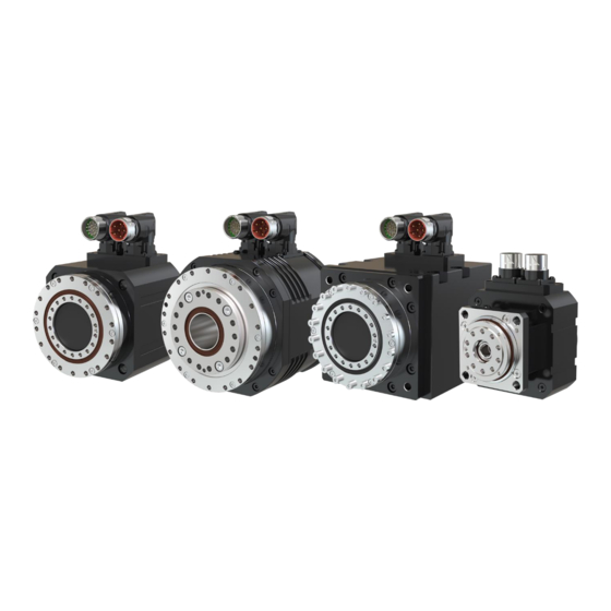
Page 12: Product Characteristics
3 Product characteristics ▪ Electric actuator DriveSpin® represents a combination of high precision bearing reduction gear TwinSpin® with implemented axial – radial bearing with high loading ability by tilting momentum at the output, optimized servomotor (permanent magnet synchronous motor), motor feedback position sensor, and brake option –... - Page 13 Before starting the work and using the electric actuators DriveSpin® the manufacturer recommends becoming familiar with the below stated documents (if available): The latest catalogue DriveSpin® available for downloading on the website: www.spinea.com, Operating Manual – Electric Actuators DriveSpin® (this manual), Testing protocol / test report (an integral part of the electric actuator DriveSpin®...
-
Page 14: Production Label
Type designation represents also an ordering code for particular DriveSpin® electric actuator specification, it is described in detail in the DriveSpin® catalogue or on the websites http://www.spinea.com. Identification label of electric actuator DS, DSH, DSM, DSF for size 050 Identification label of other electric actuators DriveSpin®... -
Page 15: Electric Actuators Dimensions
4 Electric actuators dimensions ▪ Dimensions of electric actuators are stated in the DriveSpin® electric actuators catalogue, section Drawings, or in actual offer documentation. -
Page 16: Installation And Operation
Electric actuator DriveSpin® should be properly centered to ensure that its output flange isn´t loaded above limits. Follow the permitted axial and radial load stated in the catalogue DriveSpin® on website www.spinea.com. Avoid strokes and hitting of the electric actuator body. 5.1.3 Output flange face and circumferential jerking values ▪... -
Page 17: Installation Of Components On Electric Actuator Output Flange
12400 22750 ▪ Permitted torque transferred by the connection screws on the output flange and bearing body is stated in the catalogue DriveSpin® on the website www.spinea.com. Electric wiring DANGER! • Incorrect method of connection or touching the live parts of the device can result in equipment damage or serious injury or dead. -
Page 18: Instructions For Connection
DriveSpin®, on the website www.spinea.com, or in the Test Report of the electric actuator; in order to avoid injury or eventual damage of the equipment electric parts. -
Page 19: Protection Against Overloading
CAUTION! • Exceeded maximum permitted temperature on the electric actuator gear body, stated in the catalogue DriveSpin® on the website www.spinea.com, can irreversibly damage the electric actuator! Monitor the temperature and the heating rate of electric actuator reduction gear surface, depending on the loading. - Page 20 Electric actuator shouldn´t be used as a lifting device! ▪ Check the following terms prior to equipment commissioning: Electric actuator shouldn’t be damaged or locked. Measure the winding isolation resistance after long time storage. All cable joints must be correctly interconnected and without mechanical damage. Check the rotary seals of the electric actuator which must not be damaged No signs or sources of eventual danger are permissible.
-
Page 21: Maintenance And Disposal
• Control and protective devices must be in operation in all conditions (also during trial operation). • Electric actuator must be connected to PE bus in the electric machine distributor in a reliable way; electric safety depends on the lowest possible earth connection resistance. -
Page 22: Maintenance
▪ Follow all instructions stated in chapter 1 and 2 hereof before starting the work with the equipment. Maintenance 6.1.1 Visual check ▪ Visually check the whole electric actuator and all cable joints with focus on external damage. ▪ Radial sealing bearings are subject to wear. Therefore, check the electric actuator during a visual inspection for seal leaks and grease leakage. -
Page 23: Disposal
6.1.5 Disposal ▪ Upon the operating life expiration, dispose the electric actuator in compliance with local regulations and waste/ oil product liquidation legislation in order to avoid endangering of persons, animals and environment. CAUTION! • Solvents and lubricants can contaminate soil and water! Avoid spreading and spilling of leaked medium in the soil, water flows drains and sewers. -
Page 24: Malfunction During Operation
7 Malfunction during operation CAUTION! • Change at standard electric actuator behavior during operation can indicate the electric actuator damage or destruction! Immediately stop the drive and disconnect the electric actuator or servo – amplifier from the power supply. Don´t attempt to restart the electric actuator unless the damage or non- standard behavior cause has been removed. - Page 25 (current, speed and servo- amplifier regulation position steering loop). ▪ If you need the assistance of our technical department, please contact company SPINEA and state the following information: complete data from the identification label; type and extent of malfunction;...
-
Page 26: Technical Parameters Of Electric Actuators Drivespin
Detail wiring diagram including the description of particular pins and color marking of cable outlet conductors is described in the catalogue of electric actuators DriveSpin® on the websites: www.spinea.com, or in the test report being an integral part of every electric actuator packing. -
Page 27: Technical Specification Of Temperature Sensors
Technical specification of temperature sensor 8.5.1 Temperature sensor PTC 111-K13 ▪ Because of high non- linear thermal characteristics, PTC sensor can be used only to monitor the temperature of electric actuator DriveSpin® winding. Table 6 Table of PTC thermal resistor electric resistance values depending on temperature PTC 111-K13 = 140 °C Resistance value pursuant to DIN 44081 and DIN 44082... -
Page 28: Temperature Sensor Pt 1000
8.5.2 Temperature sensor PT 1000 ▪ Typical characteristics of temperature sensor type PT 1000 are stated in the table No. 7 and its graphical interpretation is on the picture No. 1. Table No. 7 Table of PT1000 thermal resistor electric resistance values depending on temperature Temperature [°C] Resistance [Ω] 1000... - Page 29 2500 2000 1500 1000 -100 Temperature [°C] Figure 2 Thermal dependence of PT1000...
-
Page 30: Certificates, Regulations And Directives
9 Certificates, regulations and directives REACH (Registration, Evaluation, Authorization and Restriction of Chemicals) ▪ Regulation of European Parliament on Registration, Evaluation, Authorization and Restriction of Chemical Substances. RoHS (Restriction of the Use of Certain Hazardous Substances in Electrical and Electronic Equipment) ▪... - Page 31 SPINEA, s.r.o. Ku Magašu 702/3 080 01 Haniska, District of Prešov Slovakia, EU Company ID:31687580 Tel: +421 51 770 01 56 E-mail: info@spinea.com Web: www.spinea.com Version: 25.2.2021...
Need help?
Do you have a question about the DRIVESPIN Series and is the answer not in the manual?
Questions and answers