
Subscribe to Our Youtube Channel
Summary of Contents for EDI CMU-24VDC-ITL Series
- Page 1 CMU-24VDC-ITL Low Voltage DC Cabinet Monitor Unit Operations Manual THIS MANUAL CONTAINS TECHNICAL INFORMATION FOR THE CMU-24VDC-ITL SERIES ITS CABINET MONITOR UNIT. REVISION: OCTOBER 2008 pn 888-3912-002...
- Page 2 THE CMU-24VDC SERIES CABINET MONITOR UNIT IS DESIGNED AND MANUFACTURED IN THE USA BY EBERLE DESIGN INC. PHOENIX, ARIZONA. AN ISO 9001:2015 REGISTERED COMPANY INFORMATION CONTAINED HEREIN IS PROPRIETARY TECHNICAL INFORMATION OF EBERLE DESIGN INC. PUBLICATION, REPRODUCTION OR USE IN WHOLE OR PART IS NOT PERMITTED EXCEPT UNDER TERMS AGREED UPON IN WRITING.
-
Page 3: Table Of Contents
Table of Contents Section 1 GENERAL ......................1 1.1 Overview ........................ 1 1.2 Channel Configuration .................... 1 1.3 Auxiliary Monitor Unit ..................... 1 1.4 CMU-24VDC Programming ..................2 1.5 ECcom Software Interface ..................2 1.6 Serial Bus #1 ......................2 1.6.1 Serial Bus #1 Message Types ............... - Page 4 3.4.5 Circuit Breaker (CB) Trip Status ..............12 3.4.6 Front / Rear Door Switch ................13 3.5 Monitor Interlock ....................13 3.6 External Test Reset input ..................13 3.7 Serial Bus #1 Address Inputs ................13 3.8 Serial Bus #1 Disable input ...................13 3.9 PDA Temperature ....................13 Section 4 FRONT PANEL DESCRIPTION ...............14 4.1 Indicators ......................14 4.1.1 Power Indicator ....................14...
-
Page 5: Section 1 General
CMU-24VDC-ITL Cabinet Monitor Unit Operations Manual Section 1 GENERAL 1.1 OVERVIEW The model CMU-24VDC Cabinet Monitor Unit (CMU-24VDC) is the principle part of the ITS Traffic Control Cabinet Monitoring System. It is resident in the Power Distribution Assembly and communicates with an Auxiliary Monitor Unit (AMU) located in each Output Assembly via Serial Bus #3. -
Page 6: Cmu-24Vdc Programming
CMU-24VDC-ITL Cabinet Monitor Unit Operations Manual AMU #1 AMU #2 AMU #3 AMU #4 Monitored Channels none None 1 thru 12 None 1 thru 18 1 thru 24 none reserved 1 thru 20 reserved 1 thru 26 The ATC must verify that all output assemblies being driven by a Serial Interface Unit (SIU) are being monitored by an AMU-24VDC and that the AMU-24VDC is enabled by the programming in the CMU-24VDC. -
Page 7: Serial Bus #1 Message Types
CMU-24VDC-ITL Cabinet Monitor Unit Operations Manual 1.6.1 SERIAL BUS #1 MESSAGE TYPES The CMU-24VDC is compatible with the following message types: Type 60 Module Identification Command / Type 188 Module Identification Response Type 61 Load Switch Drivers Command / Type 189 CMU Status Response Type 62 Set FSA Command / Type 190 FSA Response Type 65 Get CMU Configuration Command / Type 193 CMU Configuration Response Type 66 Time and Date Broadcast Command... -
Page 8: Section 2 Monitor Functions
CMU-24VDC-ITL Cabinet Monitor Unit Operations Manual Section 2 MONITOR FUNCTIONS 2.1 CABINET POWER SUPPLY MONITOR The CMU-24VDC will sense the Cabinet +24VDC MONITOR and +12VDC MONITOR power supply sources. The CMU-24VDC will also sense the Cabinet +24VDC MONITOR state in each Output Assembly as reported by each AMU. Voltages equal to or greater than +22 Vdc and +11 Vdc respectively will not cause a LFSA. -
Page 9: Type 62 Fsa Message
CMU-24VDC-ITL Cabinet Monitor Unit Operations Manual CMU-24VDC Power Fail resets the LFSA-R, the SB #3 timeout count will be reset to two, such that the next SB #3 timeout results in a LFSA-R. A SB #3 timeout failure during the programmed Minimum Flash time or during a CMU- 24VDC Power Failure will not cause a FSA. -
Page 10: Yellow Clearance Monitor
CMU-24VDC-ITL Cabinet Monitor Unit Operations Manual Multiple Input monitoring will be disabled when the MC COIL STATUS input is not active. There is programming in the Datakey to disable Multiple Indication monitoring on a color combination basis (G+Y, Y+R, G+R) for each channel. 2.7 YELLOW CLEARANCE MONITOR The CMU-24VDC will verify that the Yellow Change interval is at least 2.7 +/-0.1 seconds. -
Page 11: Cmu Power Failure
CMU-24VDC-ITL Cabinet Monitor Unit Operations Manual When a transition from the inactive state to the active state or a transition from the active state to the inactive state is absent for greater than 2500 milliseconds, the CMU-24VDC will set a status bit in the Type 189 frame. This alarm condition will not cause a FSA. It should cause the appropriate response in the ATC. -
Page 12: Field Check Mode
CMU-24VDC-ITL Cabinet Monitor Unit Operations Manual output commands. This diagnostic information may then be used to isolate whether the fault condition was caused by an ATC malfunction or a failure in the load switch and/or field wiring. The Field Output Check function is enabled for each channel input individually and provides two modes of operation, Field Check Mode and Field Check Status. -
Page 13: Nonvolatile Memory Diagnostic
CMU-24VDC-ITL Cabinet Monitor Unit Operations Manual 2.14.2 NONVOLATILE MEMORY DIAGNOSTIC This test will verify that the nonvolatile flash ROM and event log eeprom contain the proper data. The routine will perform a check on each ROM device and make a comparison with a check value. -
Page 14: Recurrent Pulse Detection Disable
CMU-24VDC-ITL Cabinet Monitor Unit Operations Manual vary depending on the pulse width and frequency of the recurrent inputs, but will range from 1000 ms minimum to 10.4 seconds maximum. Recurrent Pulse detection can be disabled with the SEL1 option jumper, see Section 2.15.1. 2.15.1 RECURRENT PULSE DETECTION DISABLE The Recurrent Pulse Detection function can be disabled by soldering a 0-ohm jumper into position SEL1 on the CMU-24VDC printed circuit board. -
Page 15: Section 3 Input Signals
CMU-24VDC-ITL Cabinet Monitor Unit Operations Manual Section 3 INPUT SIGNALS 3.1 FIELD SIGNAL INPUTS (LEDGUARD) The Eberle Design CMU-24VDC uses a technique designed to better monitor the characteristics of LED based signal loads called LEDguard. Each field signal input is measured and compared to both a high threshold and a low threshold value to determine On / Off status. -
Page 16: Pda Control Signal Inputs
CMU-24VDC-ITL Cabinet Monitor Unit Operations Manual A channel will be sensed active when the load current exceeds 105% of the Channel Current Sense Threshold programmed for that channel in the Datakey. A channel will not be sensed active when the load current is less than 95% of the Channel Current Sense Threshold programmed for that channel in the Datakey. -
Page 17: Front / Rear Door Switch
CMU-24VDC-ITL Cabinet Monitor Unit Operations Manual 3.4.6 FRONT / REAR DOOR SWITCH The cabinet should be wired such that +24VDC is applied to the DOOR SWITCH FRONT or DOOR SWITCH REAR inputs when the respective door is Open. These inputs will be considered active when the input voltage exceeds the Active threshold defined in Cabinet Control 5.1. -
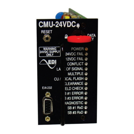
Page 18: Section 4 Front Panel Description
CMU-24VDC-ITL Cabinet Monitor Unit Operations Manual Section 4 FRONT PANEL DESCRIPTION 4.1 INDICATORS 4.1.1 POWER INDICATOR A green POWER indicator will illuminate to indicate 24VDC POWER voltage is proper. It will flash at a 2 Hz rate when the 24VDC POWER input of the CMU or AMUs are less than the DC Power Level Sense (see section 5.1). -
Page 19: Sb #3 Error Indicator
4.2 TERMINAL PORT An EIA-232-E Data Terminal Equipment (DTE) interface is provided for interconnecting to a personal computer using the EDI ECcom Signal Monitor Communications software package. See the Eberle Design ECcom Operations Manual for further details. This port is electrically isolated from the main CMU-24VDC power supply and 48VDC Ground. -
Page 20: Section 5 Specifications
CMU-24VDC-ITL Cabinet Monitor Unit Operations Manual Section 5 SPECIFICATIONS 5.1 ELECTRICAL Power Requirements Operating Voltage .................... 15 to 32 Vdc Power Consumption (maximum) ................10 Watts Voltage Monitors Field Signals High Threshold Active ..................greater than 18.5 Vrms Not Active ................... less than 17.5 Vrms Field Signals Low Threshold Active .................. -
Page 21: Mechanical
CMU-24VDC-ITL Cabinet Monitor Unit Operations Manual Multiple Fault ................... greater than 450 ms No Fault ................... less than 200 ms Typical ......................350 ms Lack of Signal Inputs Fault ..................greater than 1000 ms No Fault ................... less than 700 ms Typical ...................... -
Page 22: Section 6 Connector Assignments
CMU-24VDC-ITL Cabinet Monitor Unit Operations Manual Section 6 CONNECTOR ASSIGNMENTS 6.1 MAIN DIN CONNECTOR The CMU-24VDC main connector is a two row DIN 4161264 Header Type: Function Function +24VDC Monitor Reserved +12VDC Monitor External Test Reset VDC Ground Serial Bus #1 Disable Monitor Interlock Reserved Address 0... - Page 23 CMU-24VDC-ITL Cabinet Monitor Unit Operations Manual Pin # Function Signal Ground Reserved Reserved Reserved Reserved Eberle Design Inc. Page 19...
Need help?
Do you have a question about the CMU-24VDC-ITL Series and is the answer not in the manual?
Questions and answers