Table of Contents
Advertisement
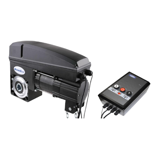
DRIVE
SHAFT-50PRO / 85PRO
Installation and service instruction
© DoorHan, 2015
REMOTE-CONTROL DESK PROGRAMMING MANUAL
O P E N
S T O P C L O S E
S T O P
CONTENTS
GENERAL INFORMATION
SAFETY REGULATIONS
DRIVE DEVICE
DRIVE INSTALLATION
ELECTRICAL INTERFACES
DRIVE PROGRAMMING
DRIVE MANUAL OPERATION
MAINTENANCE
TROUBLESHOOTING
2
3
4
5
5
6
9
14
14
14
15
Advertisement
Table of Contents

Subscribe to Our Youtube Channel
Related Manuals for DoorHan DRIVE SHAFT-50PRO

Summary of Contents for DoorHan DRIVE SHAFT-50PRO
- Page 1 ELECTRICAL INTERFACES DRIVE PROGRAMMING REMOTE-CONTROL DESK PROGRAMMING MANUAL DRIVE MANUAL OPERATION MAINTENANCE DRIVE TROUBLESHOOTING SHAFT-50PRO / 85PRO O P E N S T O P C L O S E S T O P Installation and service instruction © DoorHan, 2015...
-
Page 2: Table Of Contents
8.1. Recording of DoorHan transmitters into receiver ........ -
Page 3: General Information
GENERAL INFORMATION 1. GENERAL INFORMATION SHAFT-50PRO / 85PRO shaft type electromechanical drive is intended for automation of the balanced industrial section gate. It is pos- sible to install drive directly on the shaft or by means of intermediate chain gear (option). The drive consists of the mechanical reducer located in an oil bath, and the electric motor with remote control unit. -
Page 4: Safety Regulations
• DoorHan declines all responsibility in case of the wrong installation of a product and in case of damage during the production period. • The electric drive isn’t equipped with a fixed power line cord therefore network power supply has to be laid on to automatic system via the automatic switch with distance between the next contacts not less than 3 mm. -
Page 5: Drivedevice
DRIVE DEVICE 3. DRIVE DEVICE Release cord Hand chain Motor Control unit Transfer case Terminal switches of encoder Hand drive assembly Control device 4. DRIVE INSTALLATION 4.1. Tools Wrench set Masonry drills set Electric drill Flat blade and cross screwdrivers set Pliers Tape ruler (folding rule) Metal drills set... -
Page 6: Installation By Means Of Chain Gear
ELECTRICAL INTERFACES 4.3. Installation by means of chain gear (the optional device, isn’t included in the basic equipment) Shaft • Additional accessories for installation (a bracket, big and small chain wheels, a chain) need to be bought separately. Big rack wheel •... -
Page 7: Electric Network
ELECTRICAL INTERFACES Control unit scheme 5.1. Electric network Aerial MAIN BOARD Safety devices 1 PH CL C N 3 Safety devices 2 C N 1 Safety devices 3 Open Close Exit 24VDC Electric lock 2.5 A ARTICULAR Case switch buttons TRANSFORMATION Emergency button Motor... - Page 8 ELECTRICAL INTERFACES Photo elements connection diagram end OPTOKIT Optical sensors connection diagram (Х3) LED3 Х3 Optokit TEST 24VDC TEST ATTENTION! If the terminals and IR " – "no devices are attached, you must install a jumper between pins IR and" – ". With the exception of terminals 2 and 3 (see paragraph 6.6 «Guards adjustment») Wicket opening sensor connection diagram (Х2) Х2...
-
Page 9: Drive Programming
DRIVE PROGRAMMING 6. DRIVE PROGRAMMING 6.1. Upper stroke limitation setting Press «+» «1» will light up By pressing «+» or «-» select the value of function Press Р to save the Нажимая «+» и «–», установите полотно в необходимое Нажмите «Р» для information верхнее... - Page 10 DRIVE PROGRAMMING Operation mode 3: display shows the figure: «opening» – is caused by the holding of key «closing» – is caused by the holding of key Operation mode 4: display shows the figure: «opening» – occurs according to logics OPEN STOP CLOSE STOP «closing»...
-
Page 11: Door Automatic Closing Mode Setting
DRIVE PROGRAMMING 6.4. Door automatic closing mode setting Factory setting «4» will light up Press Р Display shows the By pressing «+» or Press Р to save the of Press «+» flashing zeros «00» «-» select the value function: 01 – 10 sec, (automatic closing 02 –... -
Page 12: Upper Gate Position Fine Adjustment
DRIVE PROGRAMMING 6.7. Upper gate position fine adjustment Setting of upper position and escaping from the programming mode shall be performed before the fine adjustment carrying out! 1. Start the door opening mode after the programming mode escaping. If it is necessary to increase or decrease the upper gate position the fine adjustment can be performed using MENU 7. -
Page 13: Lower Gate Position Fine Adjustment
DRIVE PROGRAMMING 6.8. Lower gate position fine adjustment Setting of lower position and escaping from the programming mode shall be performed before the fine adjustment carrying out! 1. Start the door closing mode after the programming mode escaping. If it is necessary to increase or decrease the lower gate position the fine adjustment can be performed using MENU 08. -
Page 14: Remote Control Transmitters Programming
9. DRIVE MANUAL OPERATION Electrical drive SHAFT-50PRO / 85PRO is equipped with manual chain reducing gear which is used in case of emergency lifting/lowering of gate if the power is switched off. For emergency operation it is necessary to pull the rope with red handle down to stop excluding the possibility of automatic start of electrical drive. -
Page 15: Troubleshooting
Odintsovsky district, Moscow region, Russia, 140002 or by e-mail: info@doorhan.ru. • The manufacturer (DoorHan) does not carry out the direct control over the installation of gate and automated equipment, their maintenance and operation and cannot be responsible for the safety of installation, operation and maintenance of gate and automated equipment. - Page 16 FOR NOTES...
- Page 17 FOR NOTES...
- Page 18 www.doorhan.com...
Need help?
Do you have a question about the DRIVE SHAFT-50PRO and is the answer not in the manual?
Questions and answers