
Summary of Contents for Geolux LX-80-15
- Page 1 LX-80-15 10 Hz Oceanographic Radar Sensor User Manual v2.4.1 Copyright ©2022 Geolux d.o.o. All rights reserved.
- Page 2 Geolux oceanographic radar sensor can be used in various applications and environments. We have created this User manual in order to assist you with setting up and using the Geolux instrument. Should there be any questions left unanswered, please feel free to contact us directly: Geolux d.o.o.
-
Page 3: Table Of Contents
Contents 1. Introduction 2. Electrical Characteristics 3. Connector Pin-Out 3.1. Serial RS-232 Interface 3.2. Serial RS-485 Interface 3.3. CAN Communication Interface (Optional) 3.4. Analog 4 – 20 mA Output 3.5. SDI-12 Interface 4. Installing the Oceanographic Radar Sensor 4.1. Measurement Through Materials (Containers) 4.2. - Page 4 7. Data Interface 7.1. Serial RS-232 Interface 7.2. Serial RS-485 Interface 8. Data Protocols 8.1. NMEA Protocol (RS-232) 8.2. Servicing Protocol (RS-232) 8.3. Modbus Protocol (RS-485) 8.4. SDI-12 Protocol 9. Geolux Instrument Configurator 10. Troubleshooting 11. Appendix A – Mechanical Assembly...
-
Page 5: Introduction
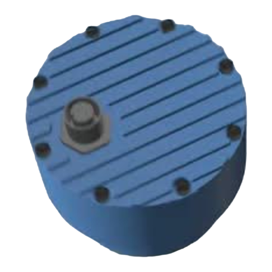
LX-80-15 10 Hz User Manual Introduction Geolux LX-80-15 10 Hz oceanographic radar sensor uses radar technology to provide precise contactless measurement of water level. Contactless radar technology enables quick and simple sensor installation above the water surface and requires minimum maintenance. This functionality... -
Page 6: Electrical Characteristics
LX-80-15 10 Hz User Manual Electrical Characteristics The electrical characteristics of the Geolux LX-80-15 10 Hz oceanographic radar sensor are given in Table 1. Table 1. Electrical Characteristics Parameter Unit Communication interface: RS-232 interface speed 9600 115200 RS-485 interface speed... -
Page 7: Connector Pin-Out
RS485 – D- RS-485 data transmitter/receiver low signal. Dark Red RS485 – D+ RS-485 data transmitter/receiver high signal. Black SDI-12 SDI-12 communication interface. Purple 4 – 20 mA Output Analog 4 – 20 mA output. LX-80-15 10 Hz Oceanographic Radar Sensor... -
Page 8: Serial Rs-232 Interface
GND (grey wire) is needed on pin 5 of the DB-9 connector. Optionally, Geolux can supply a cable with DB-9 connector connected to the cable. This requirement must be specified when placing an order. -
Page 9: Can Communication Interface (Optional)
Picture 4. If a sensing resistor is used, resistance should be selected from the range of 10 Ω up to 500 Ω, with a recommended value of 100 Ω for the sensing resistor. LX-80-15 10 Hz Oceanographic Radar Sensor... -
Page 10: Sdi-12 Interface
For hydrological applications, SDI-12 communication interface is a valid option and the instrument is natively able to communicate directly with SDI-12 master devices (dataloggers etc.). LX-80-15 10 Hz Oceanographic Radar Sensor... -
Page 11: Installing The Oceanographic Radar Sensor
Calculation of the size of circular pattern on the water surface is calculated and presented in Table 3. LX-80-15 10 Hz Oceanographic Radar Sensor... - Page 12 Water surface directly below the sensor should be void of vegetation, rocks, sand deposition or other obstacles that could affect measurements. Geolux LX-80-15 10 Hz has built-in advanced signal processing algorithms that detect interferences coming from objects close to the water surface, but these algorithms have some limitations.
-
Page 13: Measurement Through Materials (Containers)
4.2. Rain and Wind Geolux LX-80-15 10 Hz instrument has integrated internal software filters to filter out effects of rain, fog or wind on radar distance measurements. These filters, however, have some limitations. -
Page 14: Fogging And Evaporation
After setting the sensor height, the relative measurement will be calculated according to the following formula: RM=SH-D, where: RM= relative measurement, SH=sensor height, D=measured distance from the sensor to the water. LX-80-15 10 Hz Oceanographic Radar Sensor... -
Page 15: Units
4.7. Units Default measurement unit of the LX-80-15 10 Hz is millimetres. It is possible to change the measurement unit of the device using any of the aforementioned communication protocols. The following measurement units are supported: millimetres, centimetres, metres, feet and inches. -
Page 16: Wave And Tide Measurement
LX-80-15 10 Hz User Manual Wave and Tide Measurement The Geolux LX-80-15 10 Hz oceanographic radar sensor makes water level measurements at 10 Hz sampling rate, as opposed to the standard version which makes one measurement per second (1 Hz sampling rate). -
Page 17: Wave Periods
Spectrum - T CREST_SPEC The crest period can also be calculated from the power spectrum of the water level measurements using the following formula, where M and M are the zeroth and first spectral moment. LX-80-15 10 Hz Oceanographic Radar Sensor... -
Page 18: Peak Wave Period - T
Wave Analysis Length parameter. 5.3.4. Median Water Level - L This is the median water level as measured by the level radar, within the time period as defined by the Wave Analysis Length parameter. LX-80-15 10 Hz Oceanographic Radar Sensor... - Page 19 LX-80-15 10 Hz User Manual Radar Settings To change the radar settings, connect the level meter to the PC computer, and start the Geolux Instrument Configurator PC application. Through the user interface of the application, the following parameters can be configured.
- Page 20 One or two bits may be used. The default setting on most Modbus RTU devices is one stop bit, but some dataloggers may require that the instrument is configured to use Stop bit two stop bits. STOP BITS DATA LX-80-15 10 Hz Oceanographic Radar Sensor...
- Page 21 Standard deviation - This type of filter is similar to the moving average filter. It takes a number of raw measurements (as defined by Filter length parameter), then removes 20% of outliers, and calculates the average of the remaining 80% of values. LX-80-15 10 Hz Oceanographic Radar Sensor...
- Page 22 If no peak above this value is detected, the sensor will report distance equal to 0. The threshold is used to filter noise and false readings and it is recommended to keep this value between 0 and 1000. LX-80-15 10 Hz Oceanographic Radar Sensor...
- Page 23 When the radar operates in SDI-12 mode, then this parameter affects the duration returned to aM1! and aM2! commands - for more information on SDI-12 protocol see chapter 8 of this document. LX-80-15 10 Hz Oceanographic Radar Sensor...
- Page 24 Active zone max. - It is strongly recommended to set the Active zone max. value to the maximum possible distance between the water and the instrument at the specific monitoring site. Typically, this is the distance between the instrument and the lowest point in the channel. LX-80-15 10 Hz Oceanographic Radar Sensor...
- Page 25 TO S. G. Setting the sensor height relative to the measurement is done using staff gauge. The sensor will output relative measurement of the actual water level based on its height above the riverbed. LX-80-15 10 Hz Oceanographic Radar Sensor...
- Page 26 For the reconfiguration of the device which is set to operate in SDI-12 mode, it’s necessary to power-cycle the device, and then use the Geolux Instrument Configurator application to connect to the device within 1 minute after power-up. If there is no attempt to connect to the device over RS-232 within one minute, the device will automatically go back to sleep mode.
- Page 27 LX-80-15 10 Hz User Manual Data Interface Geolux LX-80-15 10 Hz radar sensor offers multiple data interfaces, in order to make the integration of the device with existing SCADA/telemetry systems easy. 7.1. Serial RS-232 Interface Serial RS-232 interface is used for direct connection of a single level meter unit with the computer. The serial interface is used both for retrieving live level measurements and for configuration of the level meter device.
- Page 28 LX-80-15 10 Hz User Manual Data Protocols Geolux LX-80 level meter supports the following data protocols: • NMEA-like protocol on RS-232 interface that constantly outputs the detected current level and averaged level, depending on the active settings for data filtering •...
- Page 29 Settings. The measured water level is filtered using averaging filer, to smooth the measured data. Filter parameters can be adjusted using the Geolux Instrument Configurator application under device Settings. Signal to Noise Ratio of the detected signal. SNR is the difference between signal level corresponding to measured distance and the noise floor level.
- Page 30 To make instrument configuration easy, Geolux provides the Geolux Instrument Configurator utility application. Regular users do not need to be concerned about the servicing protocol used between the Geolux Instrument Configurator and the level meter device. Geolux Instrument Configurator is described in the chapter 9 of this user manual.
- Page 31 1 in the 8-bit payload byte. Generally, all bytes on the receiver side where the parity bit is not matching the message will be discarded. Default setting on most devices that use Modbus is even parity. #set_modbus_parity=0 (none) #set_modbus_parity=1 (odd parity) #set_modbus_parity=2 (even parity) LX-80-15 10 Hz Oceanographic Radar Sensor...
- Page 32 The length for the moving average filter is configured separately through Filter length parameter. Median - The median filter finds the median value from a number of raw measurements. The length for the median filter is configured separately through Filter length parameter. LX-80-15 10 Hz Oceanographic Radar Sensor...
- Page 33 Last peak detector type should be used. This setting is available on units with firmware versions greater than 2.3.2. #set_peak_detector=0 (Maximum peak) #set_peak_detector=1 (Last peak) LX-80-15 10 Hz Oceanographic Radar Sensor...
- Page 34 It is strongly recommended to set the Active zone max. value to the maximum possible distance between the water and the instrument at the specific monitoring site. Typically, this is the distance between the instrument and the lowest point in the channel. #set_deadzone_max=<value> LX-80-15 10 Hz Oceanographic Radar Sensor...
- Page 35 When continuous calibration is turned on, the radar power consumption will increase for approximately 20%. This setting is available on devices with firmware versions above 2.3.9. #force_calibration=0 (Turned off) #force_calibration=1 (Turned on) LX-80-15 10 Hz Oceanographic Radar Sensor...
- Page 36 # peak_detector:0 # RX_gain:216 # unit_type:0 # wave_analysis_lenght:300 # iwr_status:1 # bandwidth:0 # nmea_protocol_flags:3 # force_calibration:1 # level_range:15000.0 # measurement_frequency:1.0 # level_offset:0.0 # deadzone_min:200.0 # deadzone_max:15000.0 # analog_output_min:0.0 # analog_output_max:15000.0 # IR_constant:500.0 # sensor_height:-0.000 LX-80-15 10 Hz Oceanographic Radar Sensor...
- Page 37 1. However, in the Modbus request packet the data start address is written as the address of the first register to read minus one. For example, to retrieve the Modbus register number 5, in Modbus data packet the address of that register should be written as 4. LX-80-15 10 Hz Oceanographic Radar Sensor...
- Page 38 2 → odd parity, 1 stop bit 3 → odd parity, 2 stop bits 4 → even parity, 1 stop bit 5 → even parity, 2 stop bits default → even parity, 1 stop bit LX-80-15 10 Hz Oceanographic Radar Sensor...
- Page 39 2 → Moving average filter postprocessing 3 → Median filter 4 → Standard deviation filter 0x001D 2 bytes 0 → mm Level unit 1 → cm 2 → m 3 → ft 4 → in LX-80-15 10 Hz Oceanographic Radar Sensor...
- Page 40 2 bytes 0 – device range in current units S_M0 0x0036 2 bytes 0 – wave analysis length in tenths of second 0x0037 2 bytes 0 – wave analysis length in tenths of second ZUC_SPEC LX-80-15 10 Hz Oceanographic Radar Sensor...
- Page 41 -32768 – 32767 in current units 0X03 0x003C 2 bytes -32768 – 32767 in current units 0x003D 2 bytes -32768 – 32767 in current units MEAN 0x003E 2 bytes -32768 – 32767 in current units LX-80-15 10 Hz Oceanographic Radar Sensor...
- Page 42 0 – device range 4-20 mA maximum value in default → device range selected unit 0x0011 2 bytes 0 – device range Level measurement offset 0x0012 2 bytes 0 – 1 IR filter constant LX-80-15 10 Hz Oceanographic Radar Sensor...
- Page 43 2 → $ANG is not sent 3 → $WAV and $ANG are not sent 0x002E 2 bytes 0 → Turned off Force continuous calibration 1 → Turned on 0x0032 2 bytes 0 –3600 Wave analysis length LX-80-15 10 Hz Oceanographic Radar Sensor...
- Page 44 (on request only) +f – SNR of latest measurement +f - standard deviation of the data in mm Additional data aD1! .. aD9! a0<CR><LF> No values are returned for a0<CRC><CR><LF> additional data. LX-80-15 10 Hz Oceanographic Radar Sensor...
- Page 45 3 – in 4 – ft Set measurement aXGLUN+d! a+d<CR><LF> +d – measurement unit for level unit for level 0 – mm 1 – cm 2 – m 3 – in 4 – ft LX-80-15 10 Hz Oceanographic Radar Sensor...
- Page 46 Set filter type for aXGLFT+t! a+t<CR><LF> +t – filter type, any of the follow- data filtering ing: 0 – no filter 1 – IIR filter 2 – Moving average 3 – Median 4 – Standard deviation LX-80-15 10 Hz Oceanographic Radar Sensor...
- Page 47 +d – NMEA protocol flag value flags value 0 – all sentences are sent 1 – $WAV is not sent 2 – $ANG is not sent 3 – $WAV and $ANG are not sent LX-80-15 10 Hz Oceanographic Radar Sensor...
- Page 48 Perform factory aXGFAC! a+1<CR><LF> Revert the device to default reset factory settings. To fully revert the device to factory settings, the device must be power-cycled after the factory reset command is executed. LX-80-15 10 Hz Oceanographic Radar Sensor...
- Page 49 0 – turned off 1 – turned on Device supports all other commands required by SDI-12 v1.3 and will respond to them but all relevant data can be acquired using the commands from the table above. LX-80-15 10 Hz Oceanographic Radar Sensor...
- Page 50 When started, Geolux Instrument Configurator displays its main window. Initially, no level data is displayed, as the connection to the instrument is not established. Picture 6. shows the Geolux Instrument Configurator main window on start-up. Picture 6. Geolux Instrument Configurator Main Window To connect the Geolux Instrument Configurator with the instrument, connect your PC to the radar using a serial cable connection.
- Page 51 LX-80-15 10 Hz User Manual Picture 7. Geolux Instrument Configurator – Data View Clicking the Settings button enables the user to configure the instrument or upgrade the device to a newer firmware version. Instrument settings are sorted into 3 groups: Interfaces, Processing and Measurement, as shown in Picture 8.
- Page 52 Picture 8. Geolux Instrument Configurator – Settings View Geolux Instrument Configurator also enables echo curve acquisition. Navigating to the Echo Curve tab and clicking the Load echo curve button loads the current echo curve, as shown in Picture 9. The echo curve plot shows the current echo curve in yellow, as well as the background echo curve in blue.
- Page 53 Clicking the Stop button stops the acquisition of the raw data, while clicking the Clear button clears the previously acquired data. Picture 10. Geolux Instrument Configurator - Raw Data View LX-80-15 10 Hz Oceanographic Radar Sensor...
- Page 54 COM port number is assigned to the COM port that is being used to establish a connection with the instrument, try setting up the connection with each COM port available in the system, until the connection is established. LX-80-15 10 Hz Oceanographic Radar Sensor...
- Page 55 RS-232 line. If the connection is established within 60 seconds after power-up, and as long as the Geolux Instrument Configurator application is connected to the sensor, it will remain in operating mode. To change between regular operating mode (Continuous scanning) and SDI-12 mode (SDI-12 automatic sleep), change the Power management parameter in the Settings tab.
- Page 56 ID, a bus conflict will happen and prohibit the master to correctly communicate with the slave devices. To resolve this problem, change the instrument’s slave device ID to a unique number through the Geolux Instrument Configurator PC application.
- Page 57 RS-232 and RS-485 (Modbus) connections. To change the instrument’s operating mode from SDI-12 mode to normal mode, first you need to connect the Geolux Instrument Configurator to the device. To establish a RS-232 connection with the device which operates in SDI-12 mode, power off the device and then power it back on.
- Page 58 ID, a bus conflict will happen and prohibit the master to correctly communicate with the slave devices. To resolve this problem, change the instrument’s SDI-12 device ID to a unique value through the Geolux Instrument Configurator PC application.
- Page 59 (magenta) wire. 4. Check the instrument configuration parameters related to 4-20 mA output Connect the instrument over RS-232 connection to the Geolux Instrument Configurator application. Check the parameters related to 4-20 mA: 4-20 mA min. and 4-20 mA max. Properly configure these parameters.
- Page 60 5. Update device firmware Connect the instrument to the Geolux Instrument Configurator PC application over RS- 232 connection. Check the active zone parameters – if the distance to the actual water surface is outside of the predefined active zone, the instrument will not be able to report the correct distance.
- Page 61 Title DWG No. Title DWG No. Geolux LX80 Level Metar Geolux LX80 Level Metar GLX2018118-M001 GLX2018118-M001 Anodized AL6061 Anodized AL6061 Rev. Date of issue Sheet Rev. Date of issue Sheet 08/2021 08/2021 RevC RevC LX-80-15 10 Hz Oceanographic Radar Sensor...
- Page 62 2022.
Need help?
Do you have a question about the LX-80-15 and is the answer not in the manual?
Questions and answers