Table of Contents
Advertisement
Quick Links
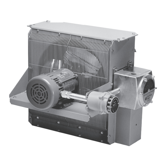
XL4 Vacucore Series
Electric Forced Air Heaters for Hazardous Locations
This manual covers the installation, maintenance, repair and replacement parts.
APPROVED LOcATiOnS
®
RUFFnEcK XL4 Vacucore
Series Electric Air Heaters are
cSA certified or UL listed for the following locations:
class i, Divisions 1 & 2, group D;
APPROVED LOcATiOnS
class ii, Division 1, groups E, F, & g;
class ii, Division 2 , groups F & g;
class i, Zones 1 & 2, group iiA
RUFFnEcK FX4-Series Explosion-Proof Electric Air Heaters are
Temperature code T3B 165˚c (329˚F);
UL listed for use in hazardous locations;
(50 Hz & 60 Hz Models)
or
class i, Division 1&2, group D;
class i, Divisions 1 & 2, groups c & D;
class ii, Division. i, group E, F, &g;
class ii, Divisions 1 & 2, groups F & g;
class i, Zones 1 & 2, groups iiA & iiB
class ii, Division 2 , group F&g.
Temperature code T3B 165˚c (329˚F);
(60 Hz Models Only)
For details of hazardous environments with potential for e
For details of hazardous locations with potential for
explosion, refer to the canadian Electrical code, Part 1,
Section 18 or national Electrical code articles 500-516.
READ ALL iMPORTAnT nOTicES On PAgE 3.
Part no. 6702-1
cERTiFiED
Ruffneck and Vacucore are registered trademarks. copyright © 2000. All rights reserved.
Owner's Manual
XL 4 20 - 480 3 60 - 35
MODEL SERIES
W A R n i n g !
Thermon Heating Systems, Inc.
TM
®
M O D E L c O D i n g
KILOWATT RATING
HERTZ
PHASE
VOLTAGE
FAN SIZE (INCHES)
4th GENERATION
Printed in canada
LiSTED
Advertisement
Table of Contents

Summary of Contents for Ruffneck XL4 Vacucore Series
- Page 1 Section 18 or national Electrical code articles 500-516. W A R n i n g ! READ ALL iMPORTAnT nOTicES On PAgE 3. Part no. 6702-1 Printed in canada LiSTED cERTiFiED Thermon Heating Systems, Inc. Ruffneck and Vacucore are registered trademarks. copyright © 2000. All rights reserved.
- Page 2 HEATER MAinTEnAncE cHEcKLiST For Electric Forced Air Heaters Heater Model: _____________________________ Serial no.: _______________________________ Date of Maintenance: _______________________ Maintenance Done By: ____________________ comments: _________________________________________________________________________ __________________________________________________________________________________ WARning Disconnect heater from the power supply before opening enclosures or servicing heater. Lock the switch in the “OFF” (open) position and/or tag the switch to prevent unexpected power application. This heater should only be serviced by personnel with heating and hazardous location equipment experience.
- Page 3 i M P O R T A n T n O T i c E S WARning Read and adhere to the following. Failure to do so may result in severe or fatal injury. Read and follow all instructions in this manual. “installation - Mechanical”...
- Page 4 M O U n T i n g MAXIMUM TILT ANGLES (Either direction) (EITHER DIRECTION) The heater must be permanently mounted in a level, upright position for operation. See Figures 2, 3, and 4 1/2 " 1" for maximum tilt angles, installation clearances, and (12.7mm) (25.4mm) physical dimensions.
-
Page 5: Wiring Diagrams
Rear View of Heater 1“ nPT opening Air exits through for field wiring louvers. rotation intake Motor junction box control enclosure and cover Do not install conduit below heater (see Figure 3). FigURE 5 control Enclosure & Field Wiring connect supply conductors to this side of contactor. -
Page 6: Repair And Replacement
REPAiR & REPLAcEMEnT R e m o v e t h i s core mounting b o l t & t w o W A R n i n g others on the Loosen opposite side. bolts Disconnect power supply before opening enclosures or only, servicing heater. -
Page 7: Printed Circuit Board
#2 are not interchangeable and have left hand threads on one end, this end is indicated by a machined groove. Remove the 2 piece fan guard assembly (see Figure 14). Lift the motor assembly off the motor mount. Before removing the fan, measure and record the location of the fan hub on the motor shaft (see Figure 15). - Page 8 HEATER ASSEMBLy DiAgRAM See control enclosure assembly diagram (below) See high-limit assembly diagram (below) Optional built-in thermostat replaces item #16 cOnTROL EncLOSURE HigH LiMiT ASSEMBLy DiAgRAM ASSEMBLy DiAgRAM BUS-BAR cOnFigURATiOn BUS-BAR cOnFigURATiOn BUS-BAR cOnFigURATiOn BUS-BAR cOnFigURATiOn ALL 1-PHASE MODELS FOR ALL 3-PHASE (EXcEPT 380 50 HERTZ) 3-PHASE 380 VOLT 50 HERTZ MODELS OnLy ALL 3-PHASE MODELS (EXcEPT 380 VOLT 50 HERTZ) - 8 -...
-
Page 9: Parts List
P A R T S L i S T F O R c E D A i R E L E c T R i c H E A T E R S Please have model and serial number P A R T n U M B E R available before calling. - Page 10 SPEciFicATiOnS FOR ALL 60 HZ MODELS nominal kW Max. Altitude (ft.) 12,000 8,000 10,000 7,000 10,000 7,000 10,000 7,000 6,000 3,658 2,438 3,048 2,134 3,048 2,134 3,048 2,134 1,829 @ 70 o F Air Flow (cFM) 1750 3600 3950 @ 21 o c (m 3 /hr.) 1444 2973...
- Page 11 SPEciFicATiOnS FOR ALL 50 HZ MODELS nominal kW 3.7 & 4.2 6.3 & 7.5 12.5 & 12.6 14.9 & 16.7 20.9 22.4 Max. Altitude (ft.) 12,000 8,000 10,000 7,000 10,000 7,000 10,000 7,000 3,658 2,438 3,048 2,134 3,048 2,134 3,048 2,134 @ 70 o F Air Flow...
- Page 12 TEcHnicAL DATA FOR ALL cSA cERTiFiED 60 HZ ELEcTRic AiR HEATERS TEMPERATURE RiSE nOMinAL TOTAL cOnTAcTOR MAXiMUM MODEL VOLTAgE WATTAgE cURREnT cORE PART PART FUSE SiZE (kW) PHASE nUMBER nUMBER XL412-208160-3 14.4 10.5 4044 3618 XL412-240160-3 12.5 10.5 4045 3618 XL412-208360-3 10.5 4044...
- Page 13 TEcHnicAL DATA FOR ALL cSA cERTiFiED 50 HZ ELEcTRic AiR HEATERS TEMPERATURE RiSE cORE nOMinAL TOTAL MODEL cOnTAcTOR MAXiMUM VOLTAgE PART WATTAgE cURREnT PART FUSE SiZE (kW) PHASE nUMBER nUMBER XL412-220150-2.5 11.4 19.7 4045 3618 XL412-220150-4.2 19.1 33.2 18.4 4049 3618 XL412-220150-6.3 28.6...
- Page 14 - 14 -...
- Page 15 - 15 -...
- Page 16 5918 Roper Road, Edmonton, Alberta, Canada T6B 3E1 Phone: (780) 466-3178 Fax: (780) 468-5904 www.thermon.com PLEASE ADHERE TO INSTRUCTIONS PUBLISHED IN THIS MANUAL. Failure to do so may be dangerous and may void certain provisions of your warranty. For further assistance, please call: 24 Hr.
Need help?
Do you have a question about the XL4 Vacucore Series and is the answer not in the manual?
Questions and answers