Table of Contents
Advertisement
Quick Links
Advertisement
Table of Contents

Summary of Contents for LTH Electronics MTD75
- Page 1 MTD75 Cooling Tower Controller Operation Guide...
-
Page 3: Preface
Preface Product warranty The MTD75 has a warranty against defects in materials and workmanship for three years from the date of shipment. During this period LTH will, at its own discretion, either repair or replace products that prove to be defective. The associated software is provided ‘as is’... - Page 4 Disposal As per regulation S.I. 2012/3032 and directive 2012/19/EU, please observe the applicable local or national regulations concerning the disposal of waste electrical and electronic equipment. - 2 - MTD75 Operation Guide...
- Page 5 Preface Declaration of Conformity MTD75 Operation Guide - 3 -...
- Page 6 Preface - 4 - MTD75 Operation Guide...
-
Page 7: Table Of Contents
MTD75 Controller Specification ..............11 Installation – Safety & EMC ................17 Noise suppression ....................18 MTD75 Add-in Cards Installation ..............19 MTD75 Installation ....................25 MTD75 Connections ................... 29 Supply Voltage Connections ..............30 ... - Page 8 Control Functions ..................87 Dosing By Volume ..................87 Timed Dosing ....................87 Dosing By pH Level ..................87 Dosing From The Water Meter ..............87 Output Configuration .................. 88 - 6 - MTD75 Operation Guide...
- Page 9 SD Card Data Logging ................175 Setup SD Card Data Logging ..............175 SD Card Data Logging Graph ..............180 Viewing the SD Card Data Log on a PC ..........181 MTD75 Operation Guide - 7 -...
- Page 10 Appendix E – Modbus RS485 Coils .............. 233 Appendix F – Modbus RS485 Discretes ............. 235 Appendix G – Error Messages ............... 245 Appendix H – Fault Finding ................253 Index ........................260 - 8 - MTD75 Operation Guide...
-
Page 11: Introduction
Introduction Introduction The MTD75 is a microprocessor controlled cooling tower controller, designed to provide timed or measured control of pumps or solenoids for inhibitor, biocide, bleed and pH control operations in a cooling tower system. The unit can be optionally equipped to measure Conductivity, pH, Redox and Temperature levels in the cooling tower, using these levels the controller can provide a more accurate dosing and bleeding scheme. - Page 12 Introduction MXD75 Termination Overview - 10 - MTD75 Operation Guide...
-
Page 13: Mtd75 Controller Specification
Introduction MTD75 Controller Specification User defined Biocide A dose duration, triggered Biocide A Output from one of the user selectable sources: Water Volume (From Water Meter Input) Timed (Per week/day/hour) Redox (when < set level) Division of the Water Meter Input (X input pulses... - Page 14 Water Volume (From Water Meter Input) Timed (Per week/day/hour) pH (user selectable < or > level) Division of the Water Meter Input (X input pulses give one output pulse) - 12 - MTD75 Operation Guide...
- Page 15 ECS20 or ECS40 Series electrodeless conductivity Electrodeless sensor. Up to 100 meters LTH 54E. Conductivity Input (Optional) 0 to 9,999 μS/cm Electrodeless Conductivity Input 0 to 9,999 ppm Range of Measurement ± 1% of range Electrodeless Conductivity Input Accuracy MTD75 Operation Guide - 13 -...
- Page 16 20mA into 1000 ohms max. (Optional) Fully isolated to 2kV. Expandable up to 5% of any operating range and offset anywhere in that range. ±0.01mA, 3 point 0-4-20 mA for remote monitor Current Output calibration Adjustment - 14 - MTD75 Operation Guide...
- Page 17 S.I. 2016/1091 & 2014/30/EU using BS EN 61326-1: 2013. Low Voltage Directive S.I. 2016/1101 & 2014/35/EU using BS EN 61010-1: 2010. Universal 80-265V AC or DC, 15W max (fused to 1A, Power Supply accessible on the front panel) MTD75 Operation Guide - 15 -...
- Page 18 Introduction Controller Housing UL 94-V0 PC/ABS. IP66 to IEC 60529 Ingress Protection Maximum 2.7 kilograms (controller only). Weight 331 x 242 x 117 mm (H, W, D) excluding mounting Dimensions brackets. - 16 - MTD75 Operation Guide...
-
Page 19: Installation - Safety & Emc
LOCAL WIRING AND SAFETY REGULATIONS SHOULD BE STRICTLY ADHERED TO WHEN INSTALLING THIS UNIT. SHOULD THESE REGULATIONS CONFLICT WITH THE FOLLOWING INSTRUCTIONS, CONTACT LTH ELECTRONICS OR AN AUTHORISED LOCAL DISTRIBUTOR FOR ADVICE. To maintain the specified levels of Electro Magnetic Compatibility (EMC, susceptibility to and emission of electrical noise, transients and radio frequency signals) it is essential that the types of cables recommended within these instructions be used. -
Page 20: Noise Suppression
Fit an in-line mains filter close to the power terminals of the controller. In cases of very high background RF and HF noise environments, LTH can supply a length of proprietary RF suppressing mains cable. - 18 - MTD75 Operation Guide... -
Page 21: Mtd75 Add-In Cards Installation
The MTD75 can be fitted with up to 3 sensor input cards and 1 output option card. The sensor input cards are designated Input Card 1, Input Card 2 and Input Card 3. - Page 22 Insert the required input cards between the headers as shown in the following two diagrams, ensuring that the connectors are correctly aligned with the headers on the input cards. Input Card 1 & 2 Installation Side View - 20 - MTD75 Operation Guide...
- Page 23 Insert the required input card or output option card between the headers as shown in the following two diagrams, ensuring that the connectors are correctly aligned with the headers on the cards. Input Card 3 & Output Card Installation Side View MTD75 Operation Guide - 21 -...
- Page 24 Input Card 3 & Output Option Card Installation Top View To install the cards and headers into the controller, first remove the terminal cover. Then remove the two revealed screws at the bottom of the case. - 22 - MTD75 Operation Guide...
- Page 25 Match the header’s name with corresponding text on the board, as shown in the following figure. Care must be taken to align the header board with the dotted outline on the main board. MTD75 Operation Guide - 23 -...
- Page 26 Connect the power (see Supply Voltage Connections section) and check that all of the new cards have been recognised by the controller. Now consult the appropriate wiring section for details of how to connect the sensors and outputs. - 24 - MTD75 Operation Guide...
-
Page 27: Mtd75 Installation
Installation MTD75 Installation Surface Mounting The MTD75 controller is designed for fixing to a wall or other flat surface. Three 6.5mm diameter holes are provided for this purpose. Note that fasteners are not provided. MTD75 Overall Dimensions LTH Recommends using No. 10 x 1¼... - Page 28 25 – 70 mm outside diameter. (Optional – LTH Part No. 7599). The controller is then clamped using the mounting kit as follows. Note: Care should be taken not to over tighten mounting, as damage may result to enclosure. - 26 - MTD75 Operation Guide...
- Page 29 Installation Horizontal Mounting Vertical Mounting MTD75 Operation Guide - 27 -...
- Page 30 Installation Blank - 28 - MTD75 Operation Guide...
-
Page 31: Mtd75 Connections
Once the cover has been removed the following terminal arrangement should be visible. MTD75 terminal label The cables should be fed through the cable glands. After each cable has been attached, pull most of the cable slack back through the cable gland to prevent any unwanted RF energy from being radiated inside the housing. -
Page 32: Supply Voltage Connections
Connections Supply Voltage Connections The MTD75 can be powered from 85-265V 50/60 Hz AC. The unit provides two terminals for each of the input connections “Live” & “Neutral”, plus an “Earth” terminal. This allows the supply to be “daisy chained” to other controllers. The controller uses a universal power supply that accepts a wide range of voltage and frequency inputs. -
Page 33: Relay Connections
Live and Neutral lines. The Live terminals are fused via the front panel fuses, at 2A (see diagram below). Controller Biocide A Biocide B Inhibitor Bleed Front Panel Fuse Layout Relay Pulse Rate Limits MTD75 Operation Guide - 31 -... - Page 34 The alarm relay contacts are normally open; volt free contacts, and are isolated form the rest of the instrument. The contacts are rated at 250VAC/ 30VDC @ 5A. The Alarm relay can be triggered from a user selectable source (See page 97). MTD75 Operation Guide - 32 -...
-
Page 35: Current Output Connections
Connections Current Output Connections The MTD75 can be supplied with 4 current outputs designated A to D, which can terminate into a load resistance not exceeding 750. For best noise immunity use a screened twisted pair cable, with the screen connected to Earth at one end. Use a sufficiently large cable to avoid a high resistance in the overall current loop. - Page 36 Connections Sensor Input The MTD75 can be fitted with up to three optional sensor input cards providing Redox, Electrodeless Conductivity and pH measurement inputs. Redox Measurement Installation The choice of the correct type of Redox electrode, how and where to mount it, so that it has a representative sample of solution are probably the two most important considerations when installing a Redox system.
- Page 37 Then soak the electrode in an 80°C, 3.8 Molar KCl solution for 30 minutes. Before allowing the electrode to cool in the same solution to promote flow of internal electrolyte through the liquid junction. MTD75 Operation Guide - 35 -...
-
Page 38: Redox Input Termination Information
Connections Redox Input Termination Information Redox LN10 Coax Cable Connection Details DynaProbe & ProcessProbe Cable Connection Details MTD75 Operation Guide - 36 -... - Page 39 Connections Redox 54E Extension Cable Connection Details The Redox input card of the MTD75 also provides a differential input method of wiring the redox electrode. This provides better electrical noise immunity and allows the sensor to operate in solutions where flowing electrical currents may cause measurement problems.
- Page 40 Connections DynaProbe & ProcessProbe Cable Connection Details with “Solution Ground” pH 54E Extension Cable Connection Details with “Solution Ground” MTD75 Operation Guide - 38 -...
- Page 41 Connections LTH 54E Extension Cable Connection Information S400 ProcessProbe to 54E Extension Cable Connection Details MTD75 Operation Guide - 39 -...
- Page 42 LTH provides a selection of electrodeless sensors in a variety of materials including PEEK food grade material with excellent chemical resistance and high temperature performance. Contact LTH Electronics or your local distributer for more information. To ensure correct sensor mounting the following conditions should be observed: The solution around the sensor is representative of the solution as a whole.
- Page 43 Care should also be taken to ensure to position of the sensor within the flow is correct. Ideally the probe head should be located in the centre of a T piece with the centre hole parallel with the flow. MTD75 Operation Guide - 41 -...
-
Page 44: Electrodeless Conductivity Input Termination Information
Connections Electrodeless Conductivity Input Termination Information Electrodeless Conductivity 54H Cable Connection Details Electrodeless Conductivity 54E Cable Connection Details MTD75 Operation Guide - 42 -... - Page 45 Recommended Extension Terminal Block Arrangement The following diagram details the connections required to extend a 54H cable as found on the ECS20 sensors with 54E cable. ECS20 54H Cable to 54E Extension Cable Connection Details MTD75 Operation Guide - 43 -...
- Page 46 Connections Electrodeless Conductivity 54E Extension Cable Connection Details MTD75 Operation Guide - 44 -...
- Page 47 When a new pH electrode is first fitted or changed it must be calibrated (see page 125). Depending on the application it may also need periodic re-calibration, the MTD75 provides an inbuilt count down timer which will trigger an alarm when calibration interval has expired (see page 125).
- Page 48 Then soak the electrode in an 80°C, 3.8 Molar KCl solution for 30 minutes. Before allowing the electrode to cool in the same solution to promote flow of internal electrolyte through the liquid junction. MTD75 Operation Guide - 46 -...
-
Page 49: Ph Input Termination Information
Connections pH Input Termination Information pH LN10 Coax Cable Connection Details DynaProbe & ProcessProbe Cable Connection Details MTD75 Operation Guide - 47 -... - Page 50 Connections pH 54E Extension Cable Connection Details The pH input card of the MTD75 also provides a differential input method of wiring the pH electrode. This provides better electrical noise immunity and allows the sensor to operate in solutions where flowing electrical currents may cause measurement problems.
- Page 51 Connections DynaProbe & ProcessProbe Cable Connection Details with “Solution Ground” VP6 Detachable Cable Connection Details with “Solution Ground” MTD75 Operation Guide - 49 -...
- Page 52 Connections pH 54E Extension Cable Connection Details with “Solution Ground” MTD75 Operation Guide - 50 -...
- Page 53 Connections LTH 54E Extension Cable Connection Information S400 ProcessProbe to 54E Extension Cable Connection Details VP6 Detachable Cable to 54E Extension Cable Connection Details MTD75 Operation Guide - 51 -...
-
Page 54: Digital Inputs
Connections Digital Inputs The MTD75 features 5 digital inputs, the instrument can be configured to initiate the appropriate action when the contact either closes or opens between the input pin and the reference pin (“G”). MTD75 Digital Input Connection Details Water Meter Input (Digital Input 1) The terminal marked “1”... -
Page 55: Modbus Rs485
Each segment is terminated at either end with a 120 Ω terminating resistor (not supplied). The bus length or the number of devices can be increased by introducing a repeater. MTD75 MODBUS RS485 CONNECTION DETAILS MTD75 Operation Guide - 53 -... -
Page 56: Sd Card Interface
Connections SD Card Interface The MTD75 features a SD card interface which is compatible with SD, SDHC and SDXC formatted cards (N.B. SDXC cards may need formatting by the MTD75 before use – see Configuration Menu section). The card can be removed whilst the instrument is on but only when the disk icon is not shown at the top of the display. -
Page 57: User Interface
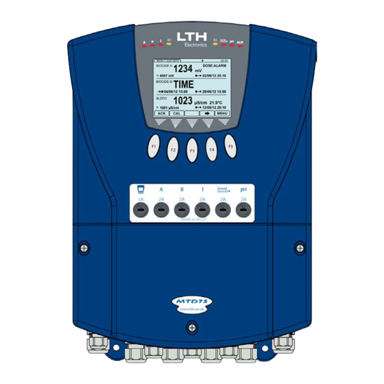
The Front Screens The MTD75 has two front screens each with the capability of showing up to three control or dosing relays. Switching between the two front screens is achieved by using the and arrows. Each relay section displays the relay’s configured function and two pieces of additional information regarding the... -
Page 58: The Menu System
20 seconds after this it will default to the front screen 1. The user interface is arranged in two ways, the first is a quick configuration overview which is accessible by scrolling left or right from the front screen as shown below. Scrolling Menu Layout MTD75 Operation Guide - 56 -... - Page 59 Note when looking at a list of options an arrow in the top right or bottom right corner of the pop-up indicates further options above or below the ones currently shown. MTD75 Operation Guide - 57 -...
-
Page 60: Security Code Access
If the code is correct the padlock at the top of the screen will turn to a key and the unit will be unlocked / – Increase / Decrease Digit – Select Next Digit – Cancel EXIT – Enter Code MTD75 Operation Guide - 58 -... -
Page 61: Access Code Management
The user is required to enter the existing security code before the new code can be entered. / – Increase / Decrease Digit – Select Next Digit – Cancel EXIT – Enter Code MTD75 Operation Guide - 59 -... -
Page 62: Enter New Code
New Code Confirmation Confirm the change of the security access code. EXIT – Cancel – Confirm Change Change Confirmation The controller will then confirm that the security code has been successfully changed. – Exit MTD75 Operation Guide - 60 -... -
Page 63: Biocide A Control Functions
Dosing By Redox Level If an optional redox card has been fitted and enabled (see pages 19 & 99) the MTD75 will allow the user to select “Redox” as the biocide A trigger. When selected the Biocide A relay will be activated when the input Redox level goes below the set level. -
Page 64: Output Configuration
Pre-Dose Bleeding The MTD75 provides the user with the option to define a short Bleed operation before initiating the Biocide A Dose, this can be defined from 1 second to 99 minutes. NB. If a bleed inhibit occurs during a pre-bleed operation the pre-bleed will be terminated and the Biocide dose initiated immediately. -
Page 65: Biocide A Menu
Biocide A relay output. Redox will only be shown if an optional redox card has been fitted and enabled (see pages 19 & 99) / – Select Option – Cancel EXIT – Save Selection MTD75 Operation Guide - 63 -... - Page 66 The volume of water required to pass before the Biocide A relay will energise. Only available when source is set to Volume / – Increase / Decrease Digit – Select Next Digit – Cancel EXIT – Save Value MTD75 Operation Guide - 64 -...
- Page 67 When “Hour” is selected this can be set to minutes and seconds, when “Day” is selected this can be set to hours and minutes. / – Increase / Decrease Digit – Select Next Digit – Cancel EXIT – Save Value MTD75 Operation Guide - 65 -...
- Page 68 – Increase / Decrease Digit – Select Next Digit – Cancel EXIT – Save Value Dose Duration Set the dose duration when using volume or timed dosing / – Select Option – Cancel EXIT – Save Selection MTD75 Operation Guide - 66 -...
- Page 69 – Save Value Time Proportional Band Set the proportional band when the output mode is set to “Time Proportional”. / – Increase / Decrease Digit – Select Next Digit – Cancel EXIT – Save Value MTD75 Operation Guide - 67 -...
- Page 70 Bleed Inhibit Time Duration of the bleed inhibit after completion of dosing (00:00 indicates bleed inhibit only during dosing). / – Increase / Decrease Digit – Select Next Digit – Cancel EXIT – Save Value MTD75 Operation Guide - 68 -...
- Page 71 – Select Next Digit – Cancel EXIT – Save Value Manual Dose Start the manual dose. Note, once started the user can cancel the manual dose by selecting stop. – Cancel EXIT – Select Option MTD75 Operation Guide - 69 -...
- Page 72 Biocide A BLANK MTD75 Operation Guide - 70 -...
-
Page 73: Biocide B Control Functions
The Biocide B relay can be activated by linking it by ratio to Biocide A. i.e. if the Ratio is set to say 3: 1, Biocide B will replace Biocide A on every fourth dose of Biocide A. This feature is only available when the Biocide A trigger source is set to “Volume” or “Time”. MTD75 Operation Guide - 71 -... - Page 74 Biocide B BLANK MTD75 Operation Guide - 72 -...
-
Page 75: Bleed Control Functions
Bleed By Volume When the “Source” menu item is set to “Volume” the MTD75 will count the volume of water given from the ‘K’ factor (see page 151) and the water meter input (see page 52). After the amount equals or exceeds the level set the Bleed relay will activate for the dose duration. -
Page 76: Bleed Menu
Bleed relay output. Elec Cond will only be shown if an optional Electrodeless Conductivity card has been fitted and enabled (see pages 19 & 101). / – Select Option EXIT – Cancel – Save Selection MTD75 Operation Guide - 74 -... - Page 77 The volume of water required to pass before the Bleed relay will energise. Only available when source is set to Volume / – Increase / Decrease Digit – Select Next Digit – Cancel EXIT – Save Value MTD75 Operation Guide - 75 -...
- Page 78 When “Hour” is selected this can be set to minutes and seconds, when “Day” is selected this can be set to hours and minutes. / – Increase / Decrease Digit – Select Next Digit – Cancel EXIT – Save Value MTD75 Operation Guide - 76 -...
- Page 79 – Increase / Decrease Digit – Select Next Digit – Cancel EXIT – Save Value Bleed Duration Set the bleed duration when using volume or timed bleeding. / – Select Option – Cancel EXIT – Save Selection MTD75 Operation Guide - 77 -...
- Page 80 – Select Next Digit – Cancel EXIT – Save Value Manual Bleed Start the manual bleed. Note, once started the user can cancel the manual bleed by selecting stop. EXIT – Cancel – Select Option MTD75 Operation Guide - 78 -...
-
Page 81: Inhibitor Control Functions
Dosing By Volume When the “Source” menu item is set to “Volume” the MTD75 will count the volume of water given from the ‘K’ factor (see page 151) and the water meter input (see page 52). After the amount equals or exceeds the level set the Inhibitor relay will activate for the dose duration. -
Page 82: Bleed Inhibiting
Inhibitor dose. Only available if the Bleed relay has been enabled. Pre-Dose Bleeding The MTD75 provides the user with the option to define a short Bleed operation before initiating the Inhibitor Dose, this can be defined from 1 second to 99 minutes. NB. If a bleed inhibit occurs during a pre-bleed operation the pre-bleed will be terminated and the Inhibitor dose initiated immediately. - Page 83 Trigger the Inhibitor relay after the entered accumulated bleed time. Only available when the source is set to “Bleed”. / – Increase / Decrease Digit – Select Next Digit – Cancel EXIT – Save Value MTD75 Operation Guide - 81 -...
- Page 84 “Day” is selected this can be set to hours and minutes. / – Increase / Decrease Digit – Select Next Digit – Cancel EXIT – Save Value MTD75 Operation Guide - 82 -...
- Page 85 – Cancel EXIT – Save Value Dose Duration Set the dose duration when using volume or timed dosing / – Increase / Decrease Digit – Select Next Digit EXIT – Cancel – Save Value MTD75 Operation Guide - 83 -...
- Page 86 Bleed Inhibit Time Duration of the bleed inhibit after completion of dosing (00:00 indicates bleed inhibit only during dosing). / – Increase / Decrease Digit – Select Next Digit – Cancel EXIT – Save Value MTD75 Operation Guide - 84 -...
- Page 87 – Select Next Digit – Cancel EXIT – Save Value Manual Dose Start the manual dose. Note, once started the user can cancel the manual dose by selecting stop. EXIT – Cancel – Select Option MTD75 Operation Guide - 85 -...
- Page 88 Inhibitor BLANK MTD75 Operation Guide - 86 -...
-
Page 89: Ph Control Functions
Dosing By pH Level If an optional pH card has been fitted and enabled (see pages 19 & 107) the MTD75 will allow the user to select “pH” as the pH Control trigger. When selected the pH Control relay will be activated when the input pH level goes depending on the pH Trigger either above or below the set level. -
Page 90: Output Configuration
Pre-Dose Bleeding The MTD75 provides the user with the option to define a short Bleed operation before initiating the pH Control Dose, this can be defined from 1 second to 99 minutes. NB. If a bleed inhibit occurs during a pre-bleed operation the pre-bleed will be terminated and the Biocide dose initiated immediately. -
Page 91: Ph Control Menu
Control relay output. pH Control will only be shown if an optional pH card has been fitted and enabled (see pages 19 & 107) / – Select Option – Cancel EXIT – Save Selection MTD75 Operation Guide - 89 -... - Page 92 – Cancel EXIT – Save Value Trigger Set whether the relay activates above or below the setpoint. Only available when source is set to pH / – Select Option EXIT – Cancel – Save Selection MTD75 Operation Guide - 90 -...
- Page 93 “Day” is selected this can be set to hours and minutes. / – Increase / Decrease Digit – Select Next Digit – Cancel EXIT – Save Value MTD75 Operation Guide - 91 -...
- Page 94 – Cancel EXIT – Save Value Dose Duration Set the dose duration when using volume or timed dosing / – Increase / Decrease Digit – Select Next Digit EXIT – Cancel – Save Value MTD75 Operation Guide - 92 -...
- Page 95 – Save Value Time Proportional Band Set the proportional band when the output mode is set to “Time Proportional”. / – Increase / Decrease Digit – Select Next Digit – Cancel EXIT – Save Value MTD75 Operation Guide - 93 -...
- Page 96 Bleed Inhibit Time Duration of the bleed inhibit after completion of dosing (00:00 indicates bleed inhibit only during dosing). / – Increase / Decrease Digit – Select Next Digit – Cancel EXIT – Save Value MTD75 Operation Guide - 94 -...
- Page 97 – Select Next Digit – Cancel EXIT – Save Value Manual Dose Start the manual dose. Note, once started the user can cancel the manual dose by selecting stop. – Cancel EXIT – Select Option MTD75 Operation Guide - 95 -...
- Page 98 Control BLANK MTD75 Operation Guide - 96 -...
-
Page 99: Alarm Relay Configuration
Selecting “Off” from the “Source” menu item can permanently deactivate the Alarm relay output. / – Select Option EXIT – Cancel – Save Selection MTD75 Operation Guide - 97 -... - Page 100 Alarm Relay BLANK MTD75 Operation Guide - 98 -...
-
Page 101: Redox Input Channel Setup
If the user has a redox card installed but is not using it, setting this to No will clear any redox sensor error messages that may be present. / – Select Option EXIT – Cancel – Save Selection MTD75 Operation Guide - 99 -... - Page 102 (from 10 seconds to 5 minutes). / – Select Option EXIT – Cancel – Save Selection MTD75 Operation Guide - 100 -...
-
Page 103: Electrodeless Conductivity Input Channel Setup
If the user has an electrodeless conductivity card installed but is not using it, setting this to No will clear any electrodeless conductivity sensor error messages that may be present. / – Select Option – Cancel EXIT – Save Selection MTD75 Operation Guide - 101 -... - Page 104 ! A Sensor loop calibration must be performed when a new sensor is attached to the controller or the sensor cable is changed; see page 117 for details. / – Select Option – Cancel EXIT – Save Selection MTD75 Operation Guide - 102 -...
- Page 105 Note. Even when disabled is set a manual temperature compensation can be used. / – Select Option – Cancel EXIT – Save Selection MTD75 Operation Guide - 103 -...
- Page 106 The fixed temperature value used for manual temperature compensation. Only available when temperature compensation mode is set to “manual”. / – Increase / Decrease Digit – Select Next Digit – Cancel EXIT – Save Value MTD75 Operation Guide - 104 -...
- Page 107 (from 10 seconds to 5 minutes). / – Select Option – Cancel EXIT – Save Selection MTD75 Operation Guide - 105 -...
- Page 108 Electrodeless Conductivity Setup BLANK MTD75 Operation Guide - 106 -...
-
Page 109: Ph Input Channel Setup
If the user has a pH installed but is not using it, setting this to No will clear any pH sensor error messages that may be present. / – Select Option – Cancel EXIT – Save Selection MTD75 Operation Guide - 107 -... - Page 110 Note. When disabled a manual temperature compensation value must be set. / – Select Option – Cancel EXIT – Save Selection Temperature Units Sets the temperature units used. / – Select Option – Cancel EXIT – Save Selection MTD75 Operation Guide - 108 -...
- Page 111 (from 10 seconds to 5 minutes). / – Select Option – Cancel EXIT – Save Selection MTD75 Operation Guide - 109 -...
- Page 112 Input Setup BLANK MTD75 Operation Guide - 110 -...
-
Page 113: Redox Input Channel Calibration
Main Menu From either of the front screen press the menu button to show the main menu options and select Calibration. / – Select Option EXIT – Return to Front Screen – Enter Option MTD75 Operation Guide - 111 -... - Page 114 When the reading is correct press the enter button to store the calibration. / – Adjust the Reading Up or Down – Cancel EXIT – Save Calibration MTD75 Operation Guide - 112 -...
- Page 115 Redox offset calibration. Cannot be edited Enter Calibration History The MTD75 series has a calibration history feature which allows the user to review the record of sensor solution calibrations. To enter the calibration history menu press enter.
- Page 116 / – Select Option – Cancel EXIT – Save Selection MTD75 Operation Guide - 114 -...
- Page 117 EXIT – Save Entry Defer Calibration Date Turns off the alarm and increases the calibration interval by an extra 7 days. Only appears once the calibration interval has expired. – Increase Interval – Cancel MTD75 Operation Guide - 115 -...
- Page 118 Redox Calibration BLANK MTD75 Operation Guide - 116 -...
-
Page 119: Electrodeless Conductivity Input Channel Calibration
As measurements are made by comparison of the readings taken in the same solution, temperature effects are less critical. However, it is essential that settings for temperature compensation are the same on both instruments. MTD75 Operation Guide - 117 -... - Page 120 If a “Cannot Edit Digital Input Has Control” message appears, then an associated digital input is currently controlling the on-line / off-line state of the channel. / – Select Option – Cancel EXIT – Save Selection MTD75 Operation Guide - 118 -...
- Page 121 When the reading is correct press the enter button to store the calibration. The calculated slope is shown in the next menu entry. / – Adjust the Reading Up or Down – Cancel EXIT – Save Calibration MTD75 Operation Guide - 119 -...
- Page 122 – Adjust the Reading Up or Down – Cancel EXIT – Save Calibration Temperature Offset Value The temperature offset value currently being used. The value will change depending on the result of the temperature offset calibration. Cannot be edited MTD75 Operation Guide - 120 -...
- Page 123 Electrodeless Conductivity Calibration Enter Calibration History The MTD75 series has a calibration history feature which allows the user to review the record of sensor solution calibrations. To enter the calibration history menu press enter. – Enter Calibration History Calibration History The calibration history page provides a record of all sensor solution calibrations carried out.
- Page 124 Sets the interval time for the calibration alarm. The Next Cal Date will update to show the date of the next calibration alarm. / – Increase / Decrease Digit – Select Next Digit – Cancel EXIT – Save Value MTD75 Operation Guide - 122 -...
- Page 125 Calibrate Sensor To start the sensor loop calibration select the “Calibrate Sensor” item from the electrodeless conductivity calibration menu. – Enter Sensor Calibration MTD75 Operation Guide - 123 -...
- Page 126 – Go to Previous Calibration Point PREV SKIP – Exit Calibration Without Saving – Exit Calibration Without Saving EXIT – Initiate Calibration MTD75 Operation Guide - 124 -...
-
Page 127: Ph Input Channel Calibration
Calibration Manual Temperature Input if manual temperature compensation is being employed. Alternatively any automatic temperature compensation element should be placed in the buffer solution with the pH sensor if Auto TC is being used. MTD75 Operation Guide - 125 -... - Page 128 If a “Cannot Edit Digital Input Has Control” message appears, then an associated digital input is currently controlling the on-line / off-line state of the channel. / – Select Option – Cancel EXIT – Save Selection MTD75 Operation Guide - 126 -...
- Page 129 – Save Value pH Calibration Enter the pH Auto Calibration routine. Only available when the calibration principle is set to auto in this menu. See page 133 for more details. – Enter pH Auto Calibration MTD75 Operation Guide - 127 -...
- Page 130 – Enter pH Manual Slope Calibration Slope Value Displays the electrode Slope currently being used by the instrument. Cannot be edited. Changed by either using the pH manual slope calibration, or by the pH auto calibration. MTD75 Operation Guide - 128 -...
- Page 131 The value will change depending on the result of the temperature offset calibration. Cannot be edited Enter Calibration History The MTD75 series has a calibration history feature which allows the user to review the record of sensor solution calibrations. To enter the calibration history menu press enter.
- Page 132 Calibration Sensor Condition The MTD75 Series is capable of analysing the result of the pH electrode offset and slope calibration and indicates to the user the condition the electrode is in. Good – The electrode is operating within set parameters.
- Page 133 The Calibration Interval will update to show the number of days to the next calibration date. / – Increase / Decrease Digit or Text – Select Next Item – Cancel EXIT – Save Entry MTD75 Operation Guide - 131 -...
- Page 134 Reset Custom Buffer – Reset the points back to the LTH standard buffer defaults. / – Select option or Increase / Decrease Digit – Select Next Digit – Cancel or Return to Calibration Menu EXIT – Save Entry MTD75 Operation Guide - 132 -...
- Page 135 / – Select Option – Cancel EXIT – Save Selection pH Auto Calibration To start the pH calibration, select the “pH Calibration” item from the desired channel’s calibration menu. – Enter pH Auto Calibration MTD75 Operation Guide - 133 -...
- Page 136 Lower down in the calibration menu the instrument will also display the sensor condition calculated from the span and offset values. See page 130 for more information. MTD75 Operation Guide - 134 -...
- Page 137 “new electrode” entry in the calibration history. / – Adjust the Reading Up or Down – Register New Electrode EXIT – Cancel – Save Calibration MTD75 Operation Guide - 135 -...
- Page 138 – Save Calibration Slope Value The adjusted slope value from the slope calibration routine is displayed here. The “Sensor Condition” function located further down the calibration menu will also update. See page 130 for more information. MTD75 Operation Guide - 136 -...
- Page 139 LTH Buffer Solutions Ordering Information Type No Part No Description SB-052-1610 138/199 4pH Buffer standard colour coded Red, 500ml. SB-168-1610 138/200 7pH Buffer standard colour coded Clear, 500ml. SB-054-1610 138/201 9pH Buffer standard colour coded Blue, 500ml. MTD75 Operation Guide - 137 -...
- Page 140 Calibration BLANK MTD75 Operation Guide - 138 -...
-
Page 141: Resetting The User Calibration
Reset User Calibration Select whether to reset the sensor calibration, the temperature calibration or reset all of the sensor’s user calibrations. / – Select Option – Return to Reset User Calibration EXIT – Enter Option MTD75 Operation Guide - 139 -... - Page 142 Calibration Reset BLANK MTD75 Operation Guide - 140 -...
-
Page 143: Current Outputs
Current Outputs Current Outputs The MTD75 Series can optionally be fitted with four current outputs designated A – D. Each individual current output can be assigned to any one of the Sensor Inputs. The current output menu contains all of the necessary setup functions to configure the current output sources. The instrument can display all of the enabled current outputs on one trend screen. - Page 144 0mA, 22mA or Hold their value when an error is detected on the input source (i.e. Sensor Fault, Temperature Fault), to provide remote warning of error conditions or to ensure fail safe operation. / – Select Option – Cancel EXIT – Save Selection MTD75 Operation Guide - 142 -...
-
Page 145: Current Output Calibration
– Select Option – Return to Main Menu EXIT – Enter Option Calibrate 4-20mA Outputs Select the current output you wish to calibrate. / – Select Option – Return to Calibration EXIT – Enter Option MTD75 Operation Guide - 143 -... - Page 146 – Save Adjustment Adjust 20mA Output Using the and buttons adjust the current output until it reads the desired value on your current meter. / – Adjust Output EXIT – Cancel – Save Adjustment MTD75 Operation Guide - 144 -...
- Page 147 – Enter Option 4-20mA Outputs Reset Select the required 4-20mA Output to Reset its user calibration back to factory settings. / – Select Option – Return to Reset User Calibration EXIT – Enter Option MTD75 Operation Guide - 145 -...
- Page 148 Current Outputs BLANK MTD75 Operation Guide - 146 -...
-
Page 149: Digital Inputs
Digital Inputs Digital Inputs The MTD75 features 5 digital inputs, the instrument can be configured to initiate the appropriate action when a contact either closes or opens between the input pin and the reference pin. Water Meter Input (Digital Input 1) The terminal marked “1”... - Page 150 Polarity Configure whether the digital input activates on the closing of the circuit (normally open) or the opening of the circuit (normally closed). / – Select Option – Cancel EXIT – Save Selection MTD75 Operation Guide - 148 -...
- Page 151 – Save Selection Remote Dose If selected enables the user to remotely dose the associated relay for the duration set in the Remote Time menu. / – Select Option – Cancel EXIT – Save Selection MTD75 Operation Guide - 149 -...
- Page 152 Digital Inputs BLANK MTD75 Operation Guide - 150 -...
-
Page 153: Configuration
– Select Option – Return to Main Menu EXIT – Enter Option Set Time Sets the controller’s time. / – Increase / Decrease Digit – Select Next Digit EXIT – Cancel – Save Time MTD75 Operation Guide - 151 -... - Page 154 Set the ‘K’ factor for the water meter input. / – Increase / Decrease Digit – Select Next Digit EXIT – Cancel – Save Value Total Water The total amount of water the controller has measured. MTD75 Operation Guide - 152 -...
- Page 155 “Water Meter Alarm” This timeout can also be used to trigger the alarm relay to indicate to external processes that the water flow has stopped. / – Select Option – Cancel EXIT – Save Selection MTD75 Operation Guide - 153 -...
- Page 156 Configuration Service Alarms The MTD75 has an inbuilt Service Alarm for each sensor input which will activate when maintenance engineer’s service interval has expired. Note. By default the alarms are disabled and can only be setup using the service access code which can be obtained from LTH Electronics.
- Page 157 Allows the users to reformat SD cards which are incompatible with the controller. For cards which are greater than 4GB this may take several minutes. / – Select Option – Return to Main Menu EXIT – Enter Option MTD75 Operation Guide - 155 -...
- Page 158 Configuration BLANK MTD75 Operation Guide - 156 -...
-
Page 159: Update Software
Update Software Update Software The MTD75 operating software can be upgraded by saving the latest version from LTH onto a SD card, inserting it into the instrument and following the instructions below. All three files must be present on the SD card for the update to work. If the card is not formatted correctly the controller will inform the user, the card must then be reformatted using the Format SD Card function. - Page 160 Update Software BLANK - 158 - MTD75 Operation Guide...
-
Page 161: Optional Software Functions
Optional Software Optional Software Functions The MTD75 series features optional software functions which when purchased will expand the controller’s capabilities. These functions by default are locked. They can be unlocked by LTH or your local distributor at the time of order. Alternatively the functions may be ordered after purchase by supplying LTH or your local distributor the serial number of your controller along with the purchase order. - Page 162 If the code is incorrect the user will be prompted to try again. If the code is correct the function will now be unlocked / – Change Character – Select Next Character EXIT – Cancel – Enter Code - 160 - MTD75 Operation Guide...
-
Page 163: Save, Restore & Reset
Save, Restore & Reset Save, Restore & Reset The MTD75 features the ability to save and restore the current configuration of the relays, sensors, current outputs and digital inputs into either one of two save slots inside the controller. Alternatively the configuration can be saved and restored via an SD card inserted into the unit, which allows the controller’s configuration to be backed up. - Page 164 Save, Restore & Reset BLANK - 162 - MTD75 Operation Guide...
-
Page 165: Error Messages
– Enter Option Error Messages For more information regarding each error message select the required message and press the help button. / – Select Error – Return to Main Menu EXIT HELP – Extended Information MTD75 Operation Guide - 163 -... - Page 166 Error Messages BLANK - 164 - MTD75 Operation Guide...
-
Page 167: Modbus Rs485
The slave response telegram consists of telegram fields which contain the requested data or which confirm that the action requested by the master has been executed. It also contains a check sum. MTD75 Modbus communication is indicated in the top of the screen by the following symbol: Supported Modbus Function Codes... - Page 168 Application: For reading measurements and the configuration of the controller’s parameters. Write Single Coil Writes a single output to either ON or OFF in the MTD75. The requested ON/OFF state is specified by the following data field: FF 00 hex = ON.
- Page 169 Byte Transmission Sequence – The bytes are transmitted in the following data order: Sequence Type Byte 3 Byte 2 Byte 1 Byte 0 FLOAT (SEEEEEEE) (EMMMMMMM) (MMMMMMMM) (MMMMMMMM) Byte 1 Byte 0 (MSB) (LSB) Byte 3 Byte 2 Byte 1 Byte 0 LONG (MSB) (LSB) MTD75 Operation Guide - 167 -...
- Page 170 – Save Value Baud Rate Set the communication Baud rate. Available options: 300, 600, 1200, 2400, 4800, 9600, 19200, 31250 and 38400 bits per second. / – Select Option – Cancel EXIT – Save Selection - 168 - MTD75 Operation Guide...
- Page 171 Modbus RS485 Parity Set the error parity bit. / – Select Option – Cancel EXIT – Save Selection MTD75 Operation Guide - 169 -...
- Page 172 Modbus RS485 BLANK - 170 - MTD75 Operation Guide...
-
Page 173: Data Logging
Data Logging Data Logging The Data logging optional software function expands the capabilities of the MTD75 controller by allowing the user to record over time the status of the controller. It consists of two separate sections, Live Trending and SD Card Data Logging, which together will help the user to analyse and improve the performance of their application. - Page 174 Enter Trace’s maximum displayed value. Adjust in conjunction with the minimum displayed value to increase the measurements displayed resolution. / – Increase / Decrease Digit – Select Next Digit – Cancel EXIT – Save Value - 172 - MTD75 Operation Guide...
- Page 175 – Save Selection Trend Interval Enter the time interval between samples for both trace 1 and trace 2. / – Increase / Decrease Digit – Select Next Digit – Cancel EXIT – Save Value MTD75 Operation Guide - 173 -...
-
Page 176: Live Trend Screen
– When in Review Mode and a SD card is present, saves a copy of the current 200 SAVE readings as a time stamped excel compatible file to the Live Trend folder on the SD card (only available when an SD card has been inserted). - 174 - MTD75 Operation Guide... -
Page 177: Sd Card Data Logging
Note. If logging at 1 sample per second, 1GB of space on the SD card will provide at least 40 Days of logging. / – Increase / Decrease Digit – Select Next Digit EXIT – Cancel – Save Value MTD75 Operation Guide - 175 -... - Page 178 Whilst the card is being searched the SD card active symbol will flash. / – Select Option EXIT – Cancel – Save Selection - 176 - MTD75 Operation Guide...
- Page 179 Note. If the SD card contains many files then there may be a delay whilst the card is searched. / – Increase / Decrease Digit – Select Next Digit – Cancel EXIT – Save Value MTD75 Operation Guide - 177 -...
- Page 180 Enter the Trace’s maximum displayed value. Adjust in conjunction with the minimum displayed value to increase the measurements displayed resolution. / – Increase / Decrease Digit – Select Next Digit EXIT – Cancel – Save Value - 178 - MTD75 Operation Guide...
- Page 181 2’s min and max as before with trace / – Select Option EXIT – Cancel – Save Selection View Graph View the configured graph. / – Select Option – Cancel EXIT – Enter Option MTD75 Operation Guide - 179 -...
-
Page 182: Sd Card Data Logging Graph
– Press to exit and return to View SD Card Data Logging menu. or – Moves the cursor across the screen. The pointed to value will be displayed at the bottom of the screen and the time at the top. - 180 - MTD75 Operation Guide... -
Page 183: Viewing The Sd Card Data Log On A Pc
! Beware the file is not protected; changes can be made and may be irreversible. If any changes are made it may affect the ability for the instrument to read the file if it is placed back into the instrument. MTD75 Operation Guide - 181 -... - Page 184 Data Logging BLANK - 182 - MTD75 Operation Guide...
-
Page 185: Appendix A - Customer Setup
Dose Tuesday Time of Day Dose Tuesday Duration Dose Wednesday Dose Wednesday Time of Day Dose Wednesday Duration Dose Thursday Dose Thursday Time of Day Dose Thursday Duration Dose Friday Dose Friday Time of Day MTD75 Operation Guide - 183 -... - Page 186 Source Mode Ratio A:B Dose After Timed Dose Dose Per Dose Every Dose Monday Dose Monday Time of Day Dose Monday Duration Dose Tuesday Dose Tuesday Time of Day Dose Tuesday Duration Dose Wednesday - 184 - MTD75 Operation Guide...
- Page 187 Bleed Inhibit Bleed Inhibit Time Pre Bleed Pre Bleed Time Manual Dose Duration Bleed Source Mode Setpoint Bleed After Timed Bleed Bleed Per Bleed Every Bleed Monday Bleed Monday Time of Day Bleed Monday Duration MTD75 Operation Guide - 185 -...
- Page 188 Bleed Sunday Duration Bleed Duration Dose Alarm Dose Alarm Time Manual Dose Duration Inhibitor Source Mode Bleed Time Dose After Timed Dose Dose Per Dose Every Dose Monday Dose Monday Time of Day Dose Monday Duration - 186 - MTD75 Operation Guide...
- Page 189 Dose Sunday Time of Day Dose Sunday Duration Dose Duration Output Mode Stroke Rate Bleed Inhibit Bleed Inhibit Time Pre Bleed Pre Bleed Time Manual Dose Duration pH Control Source Mode Setpoint Trigger Dose After Timed Dose MTD75 Operation Guide - 187 -...
- Page 190 Dose Sunday Time of Day Dose Sunday Duration Dose Duration Output Mode Stroke Rate Cycle Time Time Proportional Band Dose Alarm Dose Alarm Time Bleed Inhibit Bleed Inhibit Time Pre Bleed Pre Bleed Time Manual Dose Duration - 188 - MTD75 Operation Guide...
- Page 191 Temperature Units Temperature Compensation Temperature Compensation Mode Manual Temperature Input Temperature Compensation Base Temperature Compensation Slope ECS Filter pH Input Enabled Mode Temperature Input Sensor Temperature Units Temperature Compensation Mode Manual Temperature Input pH Filter MTD75 Operation Guide - 189 -...
- Page 192 Front Cal Access Calibration Reminder Calibration Interval Next Calibration Date pH Calibration Mode Calibration Principle Calibration Manual Temp Offset Value Slope Value Temperature Offset Sensor Condition Front Cal Access Calibration Reminder Calibration Interval Next Calibration Date - 190 - MTD75 Operation Guide...
- Page 193 Calibration Custom Buffer No. of Points Nominal Value Point Temperature Buffer Value Buffer Value Current Output A Input Source Output Zero Span On Error Current Output B Input Source Output Zero Span On Error MTD75 Operation Guide - 191 -...
- Page 194 Water Meter Polarity Digital Input 2 Function (Fixed) Flow Switch Polarity Digital Input 3 Relay Function Remote Dose Time Polarity 4-20mA OP Level Digital Input 4 Relay Function Remote Dose Time Polarity 4-20mA OP Level - 192 - MTD75 Operation Guide...
- Page 195 Redox Service Alarm Interval Electrodeless Conductivity Service Alarm Electrodeless Conductivity Service Alarm Interval pH Service Alarm pH Service Alarm Interval Optional Software Functions Modbus RS485 Data Logging Modbus RS485 Mode Slave Address Baud Rate Parity MTD75 Operation Guide - 193 -...
- Page 196 Trace 2 Max Trend Interval Live Trending 3 Configure Trend Trace 1( Trace 1 Min Trace 1 Max Trace 2(---) Trace 2 Min Trace 2 Max Trend Interval SD Card Data Logging Log Interval Loop Recording - 194 - MTD75 Operation Guide...
- Page 197 Appendix B Appendix B - Temperature Data The table below lists approximate resistance values of temperature sensors that may be used with the MTD75. Not all options are available on all sensor types. Temperature PT1000 PT100 ( C ) 1000.0...
-
Page 198: Appendix C - Temperature Coefficient
If it is difficult or impossible to evaluate the temperature compensation slope using this method, a 2.0 % / °C setting will generally give a good first approximation until the true value can be determined by independent means. - 196 - MTD75 Operation Guide... -
Page 199: Appendix D - Modbus Rs485 Registers
Alarm Relay The state of the Alarm Relay = Relay Off = Relay On Total Water Counter 2010 Total Water FLOAT The total amount of water the 0 to 9999 Cubic Meters controller has measured. MTD75 Operation Guide - 197 -... - Page 200 0 to 99.99 Cubic Meters Volume remaining till the next Biocide B Dose 2072 Bio B Last Float The volume of water measured 0 to 99.99 Cubic Meters Volume since the last Biocide B Dose - 198 - MTD75 Operation Guide...
- Page 201 The volume of water 0 to 99.99 Cubic Meters Volume remaining till the next Inhibitor Dose 2152 Inh Last Volume Float The volume of water measured 0 to 99.99 Cubic Meters since the last Inhibitor Dose MTD75 Operation Guide - 199 -...
- Page 202 2240 pH Reading FLOAT The current pH sensor pH 0.00 to 14.00 pH reading 2242 pH Temp FLOAT The current pH sensor -50.0 to 300.0 °C or Reading Temperature reading -58.0 to 572.0 °F - 200 - MTD75 Operation Guide...
- Page 203 1506 = 2 Days the dose per is set to week. 1507 = 3 Days 1508 = 4 Days 1509 = 5 Days 1510 = 6 Days 1511 = Week MTD75 Operation Guide - 201 -...
- Page 204 Thursday dose need to be 1077 = No carried out 2328 Get/Set Bio A Thu Time If dosing on a Thursday, the 0 to 23 Hour Hour time of day the dose occurs – Hour element - 202 - MTD75 Operation Guide...
- Page 205 0 to 59 Minute of day the dose occurs – Minute element 2345 Get/Set Bio A Sun Dur If dosing on a Sunday, the set 0 to 99 Minutes dose duration – Minutes element MTD75 Operation Guide - 203 -...
- Page 206 Get/Set Bio A Man Dose Set the manual dose time – 0 to 99 Minutes Minutes element 2366 Get/Set Bio A Man Dose Set the manual dose time – 0 to 59 Seconds Seconds element - 204 - MTD75 Operation Guide...
- Page 207 Monday dose need to be 1077 = No carried out 2413 Get/Set Bio B Mon Time If dosing on a Monday, the 0 to 23 Hour Hour time of day the dose occurs – Hour element MTD75 Operation Guide - 205 -...
- Page 208 0 to 59 Minute time of day the dose occurs – Minute element 2430 Get/Set Bio B Thu Dur If dosing on a Thursday, the set 0 to 99 Minutes dose duration – Minutes element - 206 - MTD75 Operation Guide...
- Page 209 – Seconds element 2447 Get/Set Bio B Day Time Set the time of day – Hour 0 to 23 Hour Hour element, when using a background dose and the dose per is set to week. MTD75 Operation Guide - 207 -...
- Page 210 Get/Set Timed Bleed The status of the background 1077 = No timed bleed enabled 1078 = Yes 2504 Get/Set Bleed Per Select the bleed cycle. 1500 = Hour 1501 = Day 1502 = Week - 208 - MTD75 Operation Guide...
- Page 211 0 to 59 Seconds set bleed duration – Seconds element 2520 Get/Set Bleed Wed If timed bleeding per week, 1076 = Yes does a Wednesday bleed need 1077 = No to be carried out MTD75 Operation Guide - 209 -...
- Page 212 Hour time of day the bleed occurs – Hour element 2537 Get/Set Bleed Sat Time If bleeding on a Saturday, the 0 to 59 Minute time of day the bleed occurs – Minute element - 210 - MTD75 Operation Guide...
- Page 213 0 to 59 Seconds Seconds element Bleed Configuration Floating Point Variables 2580 Get/Set Bleed Vol FLOAT Set the volume of water 0.01 to 99.99 Cubic Meters required to pass before the relay will energise MTD75 Operation Guide - 211 -...
- Page 214 Monday dose need to be 1077 = No carried out 2614 Get/Set Inhibitor Mon If dosing on a Monday, the 0 to 23 Hour Time Hour time of day the dose occurs – Hour element - 212 - MTD75 Operation Guide...
- Page 215 0 to 59 Minute Time Min time of day the dose occurs – Minute element 2631 Get/Set Inhibitor Thu If dosing on a Thursday, the set 0 to 99 Minutes Dur Min dose duration – Minutes element MTD75 Operation Guide - 213 -...
- Page 216 – Seconds element 2648 Get/Set Inhibitor Day Set the time of day – Hour 0 to 23 Hour Time Hour element, when using a background dose and the dose per is set to week. - 214 - MTD75 Operation Guide...
- Page 217 Generate pulse after the set 0 to 99 Pulses counts of the water meter input. 2704 Get/Set pH X Meter Generate set number of pulses 0 to 99 Pulses at each water meter input. MTD75 Operation Guide - 215 -...
- Page 218 0 to 59 Minute time of day the dose occurs – Minute element 2720 Get/Set pH Tue Dur Min INT If dosing on a Tuesday, the set 0 to 99 Minutes dose duration – Minutes element - 216 - MTD75 Operation Guide...
- Page 219 0 to 59 Seconds dose duration – Seconds element 2737 Get/Set pH Dose Sat If timed dosing per week, does 1076 = Yes a Saturday dose need to be 1077 = No carried out MTD75 Operation Guide - 217 -...
- Page 220 Get/Set pH Cycle Sec The time proportional cycle 0 to 59 Seconds time – Seconds element 2755 Get/Set pH Dose Alarm INT The status of the dose alarm 1077 = No enable 1078 = Yes - 218 - MTD75 Operation Guide...
- Page 221 Get/Set Alm Source The Alarm relay Trigger Source 1580 = Off 1581 = Power 1582 = Input 1583 = Dose 1584 = Water Meter 1585 = Flow 1586 = Tank 1587 = Any Error MTD75 Operation Guide - 219 -...
- Page 222 3003 Get/Set ECS Units The Electrodeless Conductivity 1005 = Siemens sensor units 1007 = TDS(ppm) 3004 Get/Set ECS Sensor The Electrodeless Conductivity 1180 = ECS20 Type sensor type 1181 = ECS40 1183 = CUSTOM - 220 - MTD75 Operation Guide...
- Page 223 1077 = No 3062 Get/Set ECS Cal Rem The Calibration Reminder 0-999 Days Interval Interval 3063 Get/Set ECS Cal Rem The time of the next 1-31 Day of month Date Calibration Reminder – Date element MTD75 Operation Guide - 221 -...
- Page 224 The pH Temperature -20.0 to +150.0°C or Input Compensation Manual -4.0 to +302.0°F Temperature Input pH Sensor Configuration Long Variables 3140 pH Serial No. LONG The Serial Number of the pH 0 to 9999999 input card - 222 - MTD75 Operation Guide...
- Page 225 The pH User Cal Custom 9pH 0.00 to 14.00pH 9pH 3 Buffer Point 3 3206 Get/Set pH Cal Buffer FLOAT The pH User Cal Custom Buffer -20.0 to +150.0°C or Temp 4 Temperature Point 4 -4.0 to +302.0°F MTD75 Operation Guide - 223 -...
- Page 226 The pH User Cal Custom Buffer -20.0 to +150.0°C or Temp 12 Temperature Point 12 -4.0 to +302.0°F 3256 Get/Set pH Cal Buffer FLOAT The pH User Cal Custom 4pH 0.00 to 14.00pH 4pH 12 Buffer Point 12 - 224 - MTD75 Operation Guide...
- Page 227 Get/Set Current Output FLOAT The Current Output A Span -2000 to 2000 Millivolts or A Span Equivalent Value 0 to 9999 μS/cm or 0.00 to 14.00 pH or -20.0 to +150.0°C or -4.0 to +302.0°F MTD75 Operation Guide - 225 -...
- Page 228 Get/Set Current Output FLOAT The Current Output C Zero -2000 to 2000 Millivolts or C Zero Equivalent Value 0 to 9999 μS/cm or 0.00 to 14.00 pH or -20.0 to +150.0°C or -4.0 to +302.0°F - 226 - MTD75 Operation Guide...
- Page 229 Digital Input 2 The Function Digital Input 2 is 1282 = Flow Switch Function set to. 3531 Get/Set Digital Input 2 The polarity of the digital input 1298 = Normally Open Polarity 1299 = Normally Closed MTD75 Operation Guide - 227 -...
- Page 230 Set the remote dose time – 0 to 99 Minutes Rem Dose Min Minutes element 3595 Get/Set Digital Input 4 Set the remote dose time – 0 to 59 Seconds Rem Dose Sec Seconds element - 228 - MTD75 Operation Guide...
- Page 231 3724 ECS Service The Service Alarm Interval 0 to 999 Days Alarm Interval period pH Service Alarm Configuration 3740 pH Service Is the pH Service Reminder 1076 = Yes Reminder Enabled 1077 = No MTD75 Operation Guide - 229 -...
- Page 232 Get/Set Interval Minutes Data logging Interval 0 to 59 Minutes (Minutes) 3904 Get/Set Interval Seconds Data logging Interval 0 to 59 Seconds (Seconds) 3905 Get/Set Loop Recording Loop recording 1076 = Enabled 1077 = Disabled - 230 - MTD75 Operation Guide...
- Page 233 Trace 2 Minimum Value Value Dependent on Variable Min Secondary Variable 3954 Trend 2 Value 3984 Trend 3 3926 Get/Set Trend 1 Secondary FLOAT Trace 2 Maximum Value Variable Max 3956 Trend 2 Value 3986 Trend 3 MTD75 Operation Guide - 231 -...
-
Page 234: Standard Value Tables
1646 ECS Temp 1647 1648 pH Temp 1649 Current Output C Redox 1660 1661 ECS Temp 1662 1663 pH Temp 1664 Current Output D Redox 1675 1676 ECS Temp 1677 1678 pH Temp 1679 - 232 - MTD75 Operation Guide... -
Page 235: Appendix E - Modbus Rs485 Coils
Reset Total Water Counter Defer Calibration Alarms Defer Redox Calibration Alarm Defer ECS Calibration Alarm Defer pH Calibration Alarm Defer Service Alarms Defer Redox Service Alarm Defer ECS Service Alarm Defer pH Service Alarm MTD75 Operation Guide - 233 -... - Page 236 Reset Entire Unit Data Logging Functions Start/Stop SD Card Data Logging Save Live Trend 1 Data to SD Card Save Live Trend 2 Data to SD Card Save Live Trend 3 Data to SD Card - 234 - MTD75 Operation Guide...
-
Page 237: Appendix F - Modbus Rs485 Discretes
Redox Sensor User Calibration State Redox Sensor User Calibration = Inactive = Active Electrodeless Conductivity Sensor User Calibration State Electrodeless Conductivity Sensor User Calibration = Inactive = Active Electrodeless Conductivity Temperature User Calibration = Inactive = Active MTD75 Operation Guide - 235 -... - Page 238 E008 Unit Store A Checksum Error = Inactive = Active E009 Unit Store B Checksum Error = Inactive = Active E010 Maths Error = Inactive = Active E011 Maths Error = Inactive = Active - 236 - MTD75 Operation Guide...
- Page 239 = Active E081 Electrodeless Conductivity Setup Checksum Error = Inactive = Active E082 Electrodeless Conductivity Store A Checksum Error = Inactive = Active E083 Electrodeless Conductivity Store B Checksum Error = Inactive = Active MTD75 Operation Guide - 237 -...
- Page 240 E140 pH Sensor User Cal Slope Above Specification = Inactive = Active E141 pH Sensor Input Over Range = Inactive = Active E142 pH Sensor Input Under Range = Inactive = Active E143 pH Temperature Sensor Fault = Inactive = Active - 238 - MTD75 Operation Guide...
- Page 241 E222 Bleed Store B Checksum Error = Inactive = Active E223 Bleed Setup Checksum Error = Inactive = Active E224 Bleed SD Card Checksum Error = Inactive = Active E225 Bleed Time Setting Configuration Error = Inactive = Active MTD75 Operation Guide - 239 -...
- Page 242 E304 Sensor Input Greater Than Current Output A Zero = Inactive = Active E305 Current Output A Store A Checksum Error = Inactive = Active E306 Current Output A Store B Checksum Error = Inactive = Active - 240 - MTD75 Operation Guide...
- Page 243 E348 Current Output C SD Card Checksum Error = Inactive = Active Current Output D Errors E360 Current Output D Hardware Fault = Inactive = Active E361 Sensor Input Less Than Current Output D Zero = Inactive = Active MTD75 Operation Guide - 241 -...
- Page 244 E403 Digital Input 3 SD Card Checksum Error = Inactive = Active Digital Input 4 Errors E410 Digital Input 4 Store A Checksum Error = Inactive = Active E411 Digital Input 4 Store B Checksum Error = Inactive = Active - 242 - MTD75 Operation Guide...
- Page 245 = Active E451 Data logging Store A Checksum Error = Inactive = Active E452 Data logging Store B Checksum Error = Inactive = Active E453 Data logging SD Card Checksum Error = Inactive = Active MTD75 Operation Guide - 243 -...
- Page 246 Appendix F Blank - 244 - MTD75 Operation Guide...
-
Page 247: Appendix G - Error Messages
Unit SD Card Checksum Error The SD Card store from which the entire unit was restored from has become corrupted. Check the unit's settings and then save the settings again to the SD card store. MTD75 Operation Guide - 245 -... - Page 248 E137 Sensor User Offset At Limit The last Sensor Offset Calibration was out of limits, check sensor condition and connections and repeat calibration. If the message persists please consult with your supplier. - 246 - MTD75 Operation Guide...
- Page 249 The Planned Service interval for this unit has expired. Please contact LTH E098 Electronics at the details below: E148 LTH Electronics ltd, Chaul End Lane, Luton, Beds LU4 8EZ Tel. 0044 (0) 1582 593693, Fax 0044 (0) 1582 598036 Email sales@lth.co.uk NB.
- Page 250 Inhib E264 pH Cont E284 Alarm E185 Bio A Time Setting Configuration Error E205 Bio B The dosing or control relay time settings have been incorrectly configured. E225 Bleed E245 Inhib E265 pH Cont - 248 - MTD75 Operation Guide...
- Page 251 DIG 2 The Store B Save for the digital input has become corrupted. Check the digital input's E391 settings in the digital input menu and then save the settings again in the E401 DIG 3 Save/Restore menu. E411 DIG 4 E421 DIG 5 MTD75 Operation Guide - 249 -...
- Page 252 The Basic Internal Outputs are not Operating Correctly. Try switching the unit off and then on again. If the message persists, consult with your supplier, as the unit may require to be returned for repair. - 250 - MTD75 Operation Guide...
- Page 253 The SD Card store from which the Data Logging setup was restored from has become corrupted. Check the Data Logging settings in the Data Logging menu and then save the settings again to the SD card store. MTD75 Operation Guide - 251 -...
- Page 254 Appendix G BLANK - 252 - MTD75 Operation Guide...
-
Page 255: Appendix H - Fault Finding
Using a voltmeter, set to AC or DC, check the power supply voltage at the connector. The design of the MTD75 allows the unit to accept from 85 to 250V AC or DC. Check that the power cable is securely and correctly attached. - Page 256 Check that the calibration procedure has been followed precisely. Check that the temperature compensation has been set up as required. Check that the sensor cable does not exceed the maximum specified length (sensor 5m + extension 95m). - 254 - MTD75 Operation Guide...
- Page 257 Switch the instrument power off and on again. Check that the display back-light is on, indicating power is reaching the unit. See that it displays meaningful text (Issue number etc.) in its start-up sequence, indicating processing activity. MTD75 Operation Guide - 255 -...
- Page 258 However operation at elevated temperatures or pressures, and the presence of sulphides or ionic metals, will shorten the electrode life. If the electrode cannot be set up against solutions or shows a sluggish response to changes in pH, it should be replaced. - 256 - MTD75 Operation Guide...
- Page 259 All sensors made by LTH Electronics Ltd are thoroughly tested to their published specification before despatch. As LTH have no control over the conditions in which their sensors are used, no further guarantee is given, although any complaints concerning their operation will be carefully investigated.
- Page 260 Notes - 258 - MTD75 Operation Guide...
- Page 261 Notes MTD75 Operation Guide - 259 -...
-
Page 262: Index
On Error ............. 142 Loop Resistor ........... 124 Output Scaling ........142 Manual Temperature ......119 Setup ............141 Mode ............118 Span ............142 Reminder ..........122 Zero ............142 Slope ............120 Solution ............. 119 - 260 - MTD75 Operation Guide... - Page 263 Registers ........... 197 Headers C & E ............ 21 Response Time ........167 I Setup ............168 Slave Address ........15, 168 Inhibitor .............. 79 Transmission Sequence ....... 167 Bleed Duration ........79, 81 MTD75 Operation Guide - 261 -...
- Page 264 Input Filter ..........100 Water Meter ..........52, 147 Installation ..........34 Reset ............153 Maintenance ..........34 Symbol ............56 Mode ............100 Timeout ............ 153 Sensor Enable ........... 99 Wiring ..............17 Setup ............99 - 262 - MTD75 Operation Guide...
- Page 266 Chaul End Lane Luton Bedfordshire LU4 8EZ United Kingdom Telephone: +44 (0) 1582 593693 Fax: +44 (0) 1582 598036 Email: sales@lth.co.uk Web: www.lth.co.uk...
Need help?
Do you have a question about the MTD75 and is the answer not in the manual?
Questions and answers