Table of Contents
Advertisement
Quick Links
Advertisement
Table of Contents

Summary of Contents for A&D AD-4971
- Page 1 1WMPD4002757B...
- Page 2 © 2014 A&D Company, Limited. All rights reserved. No part of this publication may be reproduced, transmitted, transcribed, or translated into any language in any form by any means without the written permission of A&D Company, Limited. The contents of this manual and the specifications of the instrument covered by this manual are subject to change for improvement without any notice and obligation on the part of the manufacturer.
-
Page 3: Table Of Contents
Features ........................... 5 1.2. Safety Precautions ........................6 Description of Individual Parts ...................... 7 2.1. General View of the AD-4971 ....................7 2.2. Display Module ........................8 2.3. I/O Box (Input & Output Module) .................... 8 Screen Operations ........................9 3.1. - Page 4 4.11.1. Inspection Results Screen ..................... 29 4.11.2. Inspection History Screen ....................30 4.11.3. Calibration Results Screen .................... 30 4.11.4. Operation History Screen ....................31 4.11.5. Error History Screen ....................... 31 Using a USB Flash Drive ......................32 5.1. Using a USB Flash Drive ...................... 32 5.1.1.
- Page 5 7.4.6. USB Memory Settings Screen ..................56 7.4.7. Language Settings Screen .................... 57 7.4.8. Software Version Screen ....................57 Modbus Communication ......................58 8.1. RTU Connection for Modbus ....................58 8.2. TCP Connection for Modbus ....................58 8.3. Reference Number for Modbus .................... 59 8.4.
- Page 6 13.3. Phase Tracking ........................77 13.4. Rotate Direction ........................78...
-
Page 7: Introduction
(removal, attachment, and tracking and tension adjustments). Functions The AD-4971 can divide products into ten groups and register a maximum of 100 products for each group (a total of 1000 products). Product images can be uploaded from a connected USB flash drive. -
Page 8: Safety Precautions
Keep hands and fingers away from the rotating parts while the AD-4971 is running. When the product falls over, spills or starts accumulating in a pile up on the conveyor, stop the AD-4971 immediately, turn off the power and take necessary actions. -
Page 9: Description Of Individual Parts
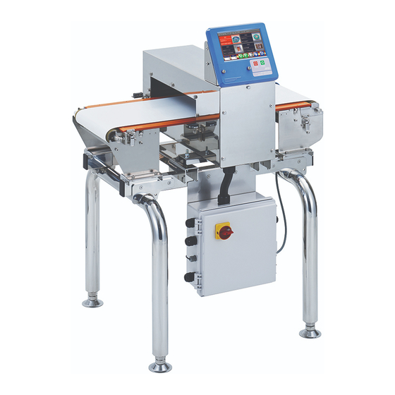
Outputs the inspection signal from the sensor unit which detects metal in the Sensor head passing product. Power switch Turns on the AD-4971 when rotating the switch clockwise on the I/O box. Frame Supports and holds the display module, sensor head and I/O box. -
Page 10: Display Module
Display Module Fig. 2 2 D D isplay Module Name Description Operation panel Displays data and allows operation of the AD-4971. STOP button Stops the conveyor belt and finishes the inspection. START button Starts the conveyor belt and begins the inspection. -
Page 11: Screen Operations
3 3 . Screen Operations 3.1. Home Menu The AD-4971 is equipped with a touch screen that can 3.Touch the tab operate the buttons, icons, input boxes, etc. on the screen. (The same operation as the "single click" of a personal computer.) -
Page 12: Character Input Dialog Box
3 Screen Operations - 3.2 Input Dialog Box 3 3 .2.2. Character Input Dialog Box When a character is required, the character input dialog box is displayed. Fig. 7 7 C C haracter Input Dialog Box Fig. 8 8 N N umerical Input Dialog Box Name Description 1 MODE button... -
Page 13: Basic Operations
4 Basic Operations - 4.1 Outline of Daily Operations 4 4 . Basic Operations 4.1. Outline of Daily Operations Turning on Refer to "4.2.1. Turning the Power ON" If inspecting a preset product If inspecting a new product Change of user management Refer to "4.4.2. -
Page 14: Turning The Power On And Off
Cautions The same operation is performed for an emergency stop. When an emergency stop has been performed, turn on the AD-4971 again only after the issue which necessitated the stop has been resolved. When emergency or failure occurs, shut off the power immediately. -
Page 15: Home Screen
4 Basic Operations - 4.3 Home Screen 4 4 .3. Home Screen Touch the "Display " icon to switch between each "Home" screen. Inspection Screen Bar Graph Screen Inspection Settings Screen Lissajous Graph Screen 4.3.1. Inspection Screen The inspection result (Good : "PASS", Defective : "FAIL") is displayed in the center of the screen. Touch the "Display "... -
Page 16: Bar Graph Screen
4 Basic Operations - 4.3 Home Screen 4 4 .3.2. Bar Graph Screen This screen displays bar graphs and peak values indicating the product effects classified by Fe, SUS and P. The inspection result ("PASS" or "FAIL") is displayed in the right upper corner of the screen. Touch the "Display "... -
Page 17: Lissajous Graph Screen
4 Basic Operations - 4.3 Home Screen 4 4 .3.3. Lissajous Graph Screen This screen displays lissajous graph. The inspection result (Good : "PASS"; Defective : "FAIL") is displayed in the right upper corner of the screen. Touch the "Display "... -
Page 18: User Management
4 Basic Operations - 4.4 User Management 4 4 .4. User Management Note The AD-4971 has default user information registered before shipment as follows: User name: Admin Password: 0000 (four zeros) User level: Administrator Change the default password to a new one and record it somewhere securely. -
Page 19: Logout
4 Basic Operations - 4.4 User Management F F ig. 1 ogin Screen N N o. N N ame D D escription 1 Login user name Current login user name is displayed. 2 User level Current login user level is displayed. 3 Logout button The button exits the current user and changes the level to "Operator". -
Page 20: Management Of User List
Note The user list cannot register a new user name which is the same as an existing one. However, the AD-4971 distinguishes upper and lower case characters so they can be used separately. Touch the "Edit " icon to display the "Edit" screen. -
Page 21: Changing User Information
4 Basic Operations - 4.5 Management of User List N N o. N N ame D D escription 1 User list User list registered in the AD-4971. 2 Registration icon "Registering a new user" screen is displayed. 3 Edit icon "Changing user Information" screen is displayed. -
Page 22: Deleting A User
Users can be deleted from the list either one at a time or all at once. Note The "Admin" default user and user login cannot be deleted. If a user without the "Admin" login logs into the AD-4971 and attempts to delete all users, the user is logged out automatically. Touch the "Edit "... -
Page 23: Target Product
The screen is displayed to edit the product data. 4.7. Product Registration The AD-4971 can use 10 product lists (groups) that can register a maximum of 100 products (items) each. The AD-4971 can register a maximum of 1000 products (items) in total. Group01... -
Page 24: Registering The Product
4 Basic Operations - 4.7 Product Registration 4 4 .7.1. Registering the Product Touch the "Product " icon in the "Home" screen to display the "Product selection" screen. Select the product using the "Left " and "Right " icons. Select a product number. Input a group number. -
Page 25: Copying The Product Data
4 Basic Operations - 4.7 Product Registration 4 4 .7.2. Copying the Product Data This function can copy the product data in the inspection group to the group in the current "Product edit" screen. Under Inspection In Product Edit Screen 01-001 02-002 02-002... -
Page 26: Registering The Image Of The Product
The space character (ASCII code: 20h) cannot be used in the name of the image file. Display the "Product edit" screen (Tab). Connect the USB flash drive to the display module of the AD-4971. Touch the "Image" button to display the "Image selection" screen. -
Page 27: Sensitivity Adjustment And Inspection Mode
Performing product registration requires a user level of "Supervisor" or higher. Warning Perform a safety check on the belt and areas surrounding the AD-4971 before operation. Ensure clothes or other loose items do not get caught in the AD-4971. Stop the AD-4971 immediately if the gear cover is removed during operation. - Page 28 4 Basic Operations - 4.8 Sensitivity Adjustment and Inspection Mode N N ote Adjust the sensitivity using the belt speed during the inspection as it cannot be changed during inspection. Take care to ensure the correct belt speed and product length are input, as these cannot be changed during the inspection.
-
Page 29: Calibration Mode
Warning Perform a safety check on the belt and areas surrounding the AD-4971 before operation. Ensure clothes or other loose items do not get caught in the AD-4971. Stop the AD-4971 immediately if the gear cover is removed during operation. -
Page 30: Starting And Stopping The Inspection
4.10.1. Starting the Inspection Warning Perform a safety check on the belt and areas surrounding the AD-4971 before operation. Ensure clothes or other loose items do not get caught in the AD-4971. Stop the AD-4971 immediately if the gear cover is removed during operation. -
Page 31: History Management
Failure when a defective product is detected and the PE sensor gives no response. out of range FAIL 3 Failure of two products Failure when two products are detected at the same time. FAIL 4 Failure of peripherals Failure when the AD-4971 has received a FAIL signal from peripherals. -
Page 32: Inspection History Screen
4 Basic Operations - 4.11 History Management 4 4 .11.2. Inspection History Screen The screen can display a maximum of the last 100 items. When connecting the USB flash drive, the history of the inspection results can be stored. Touch the "Left "... -
Page 33: Operation History Screen
4 Basic Operations - 4.11 History Management 4 4 .11.4. Operation History Screen The screen can display a maximum of the last 100 items. When connecting the USB flash drive, the operation history can be stored. Touch the "Left " icon to display the "Calibration results" screen. -
Page 34: Using A Usb Flash Drive
USB memory can be used to register product images and to store results and histories. 5.1. Using a USB Flash Drive Note The AD-4971 can use a USB flash drive with FAT32 format. Do not remove an active USB flash drive while it is accessing data. 5.1.1. Connecting a USB Flash Drive... -
Page 35: Storing The Results And The History
5 Using a USB Flash Drive - 5.2 Storing the Results and the History 5 5 .2. Storing the Results and the History 5.2.1. Storing the Inspection Results and the Calibration Results Display the "Inspection results" screen or "Calibration results" screen in the "History" screen. Connect the USB flash drive to the connector on the display module. -
Page 36: Storing The Inspection History And The Operation History
5 Using a USB Flash Drive - 5.2 Storing the Results and the History 5 5 .2.2. Storing the Inspection History and the Operation History Both are stored in USB memory with a csv format file. In the case of the inspection history, a new file is created for each inspection. In the case of the operation history, a new file is created for each inspection. -
Page 37: Formatting A Usb Memory
5 Using a USB Flash Drive - 5.3 Formatting a USB Memory Time User Details F F ig. 4 4 5 Example of O O peration History 5 5 .3. Formatting a USB Memory Note When formatting the memory, all of the data stored in memory is deleted. Back up data before formatting the memory as deleted data cannot be restored. -
Page 38: Printer
Touch the "Printer" button in the "Setting" screen (System tab) to display the "Printer" screen. Select "USB" on the "Printer" screen. Restart the AD-4971. Fig. 4 4 7 P P rinter Screen (USB) 6.1.2. Connecting a Printer to LAN Port Connect the LAN cable of the printer to the LAN port of the I/O box. -
Page 39: Reference Table Of Screens And Menu Items
7 Reference Table of Screens and Menu Items - 6.2 Printing Results and History 7 7 . Reference Table of Screens and Menu Items Table 6 he List of the Settings Screens & Tabs Items Product selection screen Product setting screen Product name Page 39 Product edit tab... - Page 40 7 Reference Table of Screens and Menu Items - 6.2 Printing Results and History Cal. error S S creens & Tabs I I tems Settings screens Page 46 Common settings tab DI setting screen DI 1 DI 2 Page 47 Configuration tab DI 3 DI 4...
-
Page 41: Product Settings Screen (Product Edit Tab)
7 Reference Table of Screens and Menu Items - 7.1 Product Settings Screen (Product Edit Tab) I I tems S S creens & Tabs Settings screens Page 53 System settings tab Date Page 54 Date/Time settings screen Time Sleep timer Page 54 LCD settings screen Brightness... -
Page 42: Product Settings Screen (Product Settings Tab)
7 Reference Table of Screens and Menu Items - 7.2 Product Settings Screen (Product Settings Tab) 7 7 .2. Product Settings Screen (Product Settings Tab) Fig. 5 5 1 P P roduct Settings Screen (Product Settings Tab) Name Description Sensitivity Adjustment button Displays the "Sensitivity adjustment screen ". - Page 43 7 Reference Table of Screens and Menu Items - 7.2 Product Settings Screen (Product Settings Tab) FAIL Limit The figure on the right depicts levels for I, Q and P when the value of the FAIL limit is set to 3.0. (The value of the sensitivity setting is 1.0) I, Q and P When the detection level exceeds the FAIL limit of the inspection, the product is deemed defective.
-
Page 44: Inspection Phase Settings Screen (Phase Tab)
It is set automatically when adjusting the sensitivity. Note If changing the phase value, the inspection may not be executed correctly. The phase value should be changed by the person authorized for managing the AD-4971. 7.2.3. Inspection Phase Settings Screen (Phase Tracking Tab) Fig. -
Page 45: Fail Behavior Settings Screen
7 Reference Table of Screens and Menu Items - 7.2 Product Settings Screen (Product Settings Tab) Phase Tracking Function This function can automatically set the value of the phase tracking when each product passes the sensor head. It can prevent inspection errors due to temperature changes, ambient conditions and product shape. The detection sensitivity becomes weak because it is based on the inspection phase when adjusting the inspection sensitivity. -
Page 46: Do Map Settings Screen
7 Reference Table of Screens and Menu Items - 7.2 Product Settings Screen (Product Settings Tab) 7 7 .2.5. DO Map Settings Screen Fig. 5 5 6 D D O Map Screen The output behavior of the DO settings can set each judgment. The item can be changed using the "Up "... -
Page 47: Do Behavior Settings Screen
Disable, Enable When stopping the motor, a DO signal is outputted. 4-3 Calibration Disable, Enable When calibrating AD-4971, a DO signal is outputted. 4-4 Setting sensitivity Disable, Enable When adjusting the sensitivity, a DO signal is outputted. 4-5 CPU run Disable, Enable When the software is executing, a DO signal is outputted. -
Page 48: Calibration Settings Screen
7 Reference Table of Screens and Menu Items - 7.3 Settings Screen (Common Settings Tab) 7 7 .2.7. Calibration Settings Screen Fig. 5 alibration Settings Screen Name Scope Description Number of phase The number of phase tracking in the calibration. 3 (0 to 10 times) adjustment 2 Number of PASS... -
Page 49: Di Settings Screen (Configuration Tab)
Reset count When receiving the DI signal, the total count is reset. Peripheral FAIL When receiving the DI signal, the AD-4971 treats it as a peripheral FAIL. 1 DI 1 Forced DO 1 When receiving the DI signal, it is outputted to the DO 1. -
Page 50: Di Settings Screen (Di Behavior Tab)
7 Reference Table of Screens and Menu Items - 7.3 Settings Screen (Common Settings Tab) 7 7 .3.2. DI Settings Screen (DI Behavior Tab) Fig. 6 6 1 D D I Settings Screen (DI Behavior Tab) Name Scope Description The waiting time from a signal input to the sampling of the DI signal for 1 Delay time 0.00 (0.00 to 9.99 sec.) the next behavior. -
Page 51: Function Settings Screen (Function 2 Tab)
7 Reference Table of Screens and Menu Items - 7.3 Settings Screen (Common Settings Tab) 7 7 .3.4. Function Settings Screen (Function 2 Tab) Fig. 6 6 3 F F unction Settings Screen (Function 2 Tab) Name Scope Description 1 Default belt speed 20.0 (10.0 to 60.0 m/min.) Initial speed of the conveyor belt. -
Page 52: Belt Speed Adjustment Screen
7 Reference Table of Screens and Menu Items - 7.3 Settings Screen (Common Settings Tab) 7 7 .3.6. Belt Speed Adjustment Screen Fig. 6 6 5 B B elt Speed Adjustment Screen This function can be used to adjust the belt speed when the belt speed specified at the sensitivity adjustment is not equal to the actual belt speed. -
Page 53: Count Settings Screen
7 Reference Table of Screens and Menu Items - 7.3 Settings Screen (Common Settings Tab) 7 7 .3.7. Count Settings Screen Fig. 6 6 6 C C ount Settings Screen Name Scope Description Counter reset at sensitivity Disable, Enable When adjusting the sensitivity, the counter for the product is reset. adjustment 2 Count overflow mode Reset, Error... -
Page 54: Connection Settings Screen (Serial Interface Tab)
7 Reference Table of Screens and Menu Items - 7.3 Settings Screen (Common Settings Tab) 7 7 .3.8. Connection Settings Screen (Serial Interface Tab) Fig. 6 onnection Settings Screen (Serial Interface Tab) Name Scope Description 1 Serial mode OFF, Cyclic print The serial communication mode. -
Page 55: Printer Settings Screen
Select the connection type of the printer. 2 IP address 192.168.110.1 Set an IP address for LAN communication. Note When you use new interface, please restart the AD-4971. 7.4. Settings Screen (System Settings Tab) Fig. 7 7 0 S S ettings Screen (System Settings Tab) Name... -
Page 56: Date / Time Settings Screen
Set the current time for the AD-4971. 3 Apply button New date and time are applied in the AD-4971. Note It may take several seconds when applying new date and time in the AD-4971. Please be aware of this time delay. 7.4.2. LCD Settings Screen Fig. -
Page 57: Lan Settings Screen
The subnet mask of the AD-4971. 3 Default gateway 0.0.0.0 The default gateway of the AD-4971. Note When you use new LAN settings, please restart the AD-4971. 7.4.4. Speaker Settings Screen Fig. 7 7 4 S S peaker Settings Screen Name... -
Page 58: Backup / Restore Screen
7 Reference Table of Screens and Menu Items - 7.4 Settings Screen (System Settings Tab) 7 7 .4.5. Backup / Restore Screen Fig. 7 7 5 B B ackup / / R R estore Screen Name Scope Description The system files are stored in the USB memory. 1 Backup 1 1 1.1.1. -
Page 59: Language Settings Screen
7 Reference Table of Screens and Menu Items - 7.4 Settings Screen (System Settings Tab) 7 7 .4.7. Language Settings Screen Fig. 7 7 7 L L anguage Settings Screen Name Scope Description 1 Language Japanese, English, Korean Language used on the panel. Note The language settings screen is always displayed in English. -
Page 60: Modbus Communication
Modbus is a communications protocol developed by Modicon, Inc. in U.S.A. Therefore, communication with Modbus enabled devices can be performed without special programs. The AD-4971 uses Modbus RTU (using the serial communication protocol of the RS-485) and Modbus TCP (with the serial communication expanded to TCP/IP). -
Page 61: Reference Number For Modbus
8 Modbus Communication - 8.3 Reference Number for Modbus 8 8 .3. Reference Number for Modbus Modbus communication uses a reference number and an address to receive a command and read and write data. The data types and reference numbers are listed in the tables below. Table 7 7 R R eference Number Data type Reference number... - Page 62 8 Modbus Communication - 8.4 Address for Modbus T T able 1 1 0 I I nput Register Address A A ddress O O utput Name O O utput Range A A ddress O O utput Name O O utput Range IP Address 1 of the metal 30001 0 to 223...
- Page 63 8 Modbus Communication - 8.4 Address for Modbus T T able 1 1 1 H H olding Register Address A A ddress O O utput Name O O utput Range A A ddress O O utput Name O O utput Range 40001 Product number 1 to 100...
- Page 64 8 Modbus Communication - 8.4 Address for Modbus Sensitivity adjustment, 40100 FAIL limit 0.1 to 99.9 40116 10.0 to 60.0 Default belt speed Sensitivity adjustment, 40101 FAIL limit 0.1 to 99.9 40117 1 to 1000 Default product length FAIL limit Sensitivity adjustment, 40102 0.1 to 99.9...
-
Page 65: General-Purpose I/O Terminals
9 General-Purpose I/O Terminals - 8.4 Address for Modbus 9 9 . General-Purpose I/O Terminals WARNING Shut down the power before connecting I/O cables. If the system is not shutdown, it may cause an electrical shock or damage parts. CAUTION When opening the I/O box, open it slowly and carefully, so as not to pull the cable. -
Page 66: Layout Of General-Purpose I/O Terminals
9 General-Purpose I/O Terminals - 9.1 Layout of General-Purpose I/O Terminals 9 9 .1. Layout of General-Purpose I/O Terminals INPUT OUTPUT OUT2 OUTPUT OUT1 Fig. 8 ayout of General-P urpose Input / utput Terminals External power supply: 24 V, 250 mA @ Maximum 9.2. -
Page 67: Output Relay Terminals
9 General-Purpose I/O Terminals - 9.2 Circuits of General-Purpose I/O Terminals 9 9 .2.2. Output Relay Terminals OUT1 OUT2 Fig. 8 8 3 C C ircuit of Output Relay Terminals (60 V, 500 mA @ Maximum) 9.2.3. Input and Output Terminals for Emergency Stop 1/2W 1/2W Fig. -
Page 68: Maintenance And Cleaning
10 Maintenance and Cleaning - 10.1 Ordinary Maintenance and Checks 1 1 0. Maintenance and Cleaning 10.1. Ordinary Maintenance and Checks 10.1.1. Check before Use (Inspection) Please be sure to check the following before the inspection. Check of contact points. Check that the position and height of the conveyor belt fits with that of the input and output devices on either side. -
Page 69: Cleaning
10 Maintenance and Cleaning - 10.2 Cleaning Saving the system file. Store the system file to USB memory. I I nformation Refer to "11.1.1. Saving the System File". 10.2. Cleaning WARNING Shut off power to the system before cleaning. When washing, make sure that the lid of the I/O box is closed. 10.2.1. -
Page 70: Maintenance Of The Conveyor Belt
Avoid pinching fingers under the conveyor belt. Do not drop the roller or belt. 10.3.1. Removing the Conveyor Belt Turn off the power to the AD-4971. Remove the four draw latches. Remove the gear case. Lift up the drive roller side of the conveyor bed (sliding plate). -
Page 71: Attaching The Conveyor Belt
10 Maintenance and Cleaning - 10.3 Maintenance of the Conveyor Belt 1 1 0.3.2. Attaching the Conveyor Belt 10.3.1. Removing the Conveyor Belt When attaching the belt, refer to " " and reattach it mostly in a reverse order from its removal. Step 1 Note Attach the conveyor belt using the reference arrow on the rear side. -
Page 72: Maintenance
The AD-4971 only supports USB memory using FAT32 format. Do not remove the active USB flash drive while it is accessing data. Do not change the directory name or filename as the AD-4971 will be unable to access the file. Touch the "Setting "... -
Page 73: Resetting To Factory Settings
CAUTION Backup the system files before this reset. A malfunction or error may occur due to the loss of the settings when resetting the AD-4971. Touch the "Backup / Restore" button in the "Settings" screen (System tab) to display the "Backup / Restore"... -
Page 74: Messages
Refer to "7.3.3. Function Settings Screen (Function 1 Tab)" 11.2.5. Error Messages The AD-4971 will display an error message when an error occurs. When an error message is displayed, follow the suggested response of the table below. Table 1 1 4 E E rror Messages... -
Page 75: Treatment Of An Error At System Initialization
Touch the "Backup / Restore" button in the "Settings" screen (System tab) to display the "Backup / Restore" screen. Touch the "Restore" button or the "Factory default" button. When the storage is finished, a restart message will be displayed. Restart the AD-4971. Information Refer to "11.1. The system file"... -
Page 76: Specifications
12 Specifications - 12.1 List of Specifications 1 1 2. Specifications 12.1. List of Specifications Model AD-4971-3510 AD-4971-3517 AD-4971-3525 Aperture height : 80 mm 150 mm 230 mm Height of the conveyor face. Aperture width : 350 mm Tunnel width of the sensor head. -
Page 77: Dimensions
12 Specifications - 12.2 Dimensions 1 1 2.2. Dimensions... -
Page 78: Appendix A : Configuration Examples
13 Appendix A : Configuration Examples - 13.1 Stop Belt Conveyor 1 1 3. Appendix A : Configuration Examples 13.1. Stop Belt Conveyor WARNING The belt stop becomes difficult depending on the conveyance situation. 13.1.1. Stop Immediately "Stop belt conveyor immediately when FAIL 1 is detected" is given as an example. Touch the "FAIL behavior"... -
Page 79: Phase Tracking In Calibration
13 Appendix A : Configuration Examples - 13.2 Phase Tracking in Calibration 1 1 3.2. Phase Tracking in Calibration Touch the "Phase" button in the "Product setting" screen (Product settings tab) to display the "Calibration settings" screen. Select an arbitrary setting for Number of phase adjustment. Display the "Calibration"... - Page 80 13 Appendix A : Configuration Examples - 13.4 Rotate Direction 1 1 3.4. Rotate Direction "Rotate CCW" is given as an example. Touch the "Function" button in the "Setting" screen (Common settings tab) to display the "Function setting” screen (Function 3 tab). Select "Rotate CCW "for Rejector rotation direction.
- Page 81 MEMO...
- Page 82 MEMO...
- Page 84 3-23-14 Higashi-Ikebukuro, Toshima-ku, Tokyo 170-0013, JAPAN Telephone: [81] (3) 5391-6132 Fax: [81] (3) 5391-6148 A&D ENGINEERING, INC. 1756 Automation Parkway, San Jose, California 95131, U.S.A. Telephone: [1] (408) 263-5333 Fax: [1] (408)263-0119 A&D INSTRUMENTS LIMITED Unit 24/26 Blacklands Way, Abingdon Business Park, Abingdon, Oxfordshire OX14 1DY United Kingdom Telephone: [44] (1235) 550420 Fax: [44] (1235) 550485 A&D AUSTRALASIA PTY LTD...
Need help?
Do you have a question about the AD-4971 and is the answer not in the manual?
Questions and answers