Table of Contents
Advertisement
Quick Links
Advertisement
Table of Contents

Subscribe to Our Youtube Channel
Related Manuals for Microhard Systems Nano Series


Summary of Contents for Microhard Systems Nano Series
- Page 1 Operating Manual Nano Series n920 | n920BD | n920X2 | n2420 900MHz/2.4GHz Spread Spectrum OEM Modules Nano Interface Card Nano Motherboard Board Nano Enclosed March 2019 150 Country Hills Landing NW Calgary, Alberta Canada T3K 5P3 Phone: (403) 248-0028 Fax: (403) 248-2762...
- Page 2 Warranty Microhard Systems Inc. warrants that each product will be free of defects in material and workmanship for a period of one (1) year for its products. The warranty commences on the date the product is shipped by Microhard Systems Inc. Microhard Systems Inc.’s sole liability and responsibility under this warranty is to repair or replace any product which is returned to it by the Buyer and which Microhard Systems Inc.
- Page 3 Usually advises against some action which could result in undesired or detrimental consequences. Point to Remember Highlights a key feature, point, or step which is noteworthy. Keeping these in mind will simply or enhance device usage. An idea or suggestion to improve efficiency or enhance usefulness. © Microhard Systems Inc.
- Page 4 This device has been modularly approved. The manufacturer, product name, and FCC and WARNING Industry Canada identifiers of this product must appear on the outside label of the end-user equipment. SAMPLE LABEL REQUIREMENT: For n920S/F/BD Nano Series OEM For n920T Nano Series OEM FCCID: NS908P24 FCCID: NS908P25 IC: 3143A-08P24 IC: 3143A-08P25 This device complies with Part 15 of the FCC Rules.
- Page 5 Updated FCC/IC Approvals, Added footprint drawing May 23, 2008 Revision 1.3 Added Pin-Out Drawing April 29, 2008 Revision 1.2 Updated FCC/IC Approvals April 21, 2008 Revision 1.1 Corrected Mechanical Drawings—Appendix E April 8, 2008 Revision 1.0 Preliminary Release March 25, 2008 © Microhard Systems Inc.
-
Page 6: Table Of Contents
2.1 Required Materials ........................12 2.2 Set-Up Procedure ........................12 3.0 Hardware Description 3.1 Nano Series OEM Module ....................... 13 3.1.1 Nano OEM Mechanical Drawing ..................14 3.1.2 Nano OEM Connectors ....................14 3.1.3 Nano OEM Pin-Out Description ..................15 3.2 High Speed Interface Description (Nano Turbo) .............. - Page 7 Binary Encryption Key ........................ 73 S217 Protocol Type ..........................74 S232 Max Buffer in Storage ......................... 74 S237 Sniff Timeout ..........................74 S244 Channel Request Mode ......................75 S248 Sync Timeout ..........................75 S251 Master Hop Allocation Timeout ....................75 © Microhard Systems Inc.
- Page 8 Appendix D: n2420 Approved Antennas ..................88 Appendix E Nano Series Layout Footprint ................... 89 Appendix F: Nano Series Development Board Schematic ............90 Appendix G: Development Board Serial Interface ................. 91 Appendix H: RS-485 Wiring ......................92 © Microhard Systems Inc.
-
Page 9: Overview
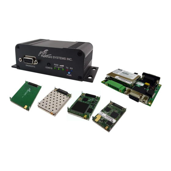
The Nano series is available as an OEM modem, as part of a development /interface kit or as a Enclosed mo- dem. When properly configured and installed, long range communications at very high speeds can be achieved. -
Page 10: Specifications
Full time Rx* Max Continuous Tx Current 1000 1300 1500 Tip: Future enhancements of Typical Tx and Rx Average the Nano Series products may require higher current Sleep Current Draw requirements than listed. It is good design practice to over spec power supplies to allow * Dependent on speed and mode. - Page 11 Operation Temperature: F(-40 C) to 185 F(85 Humidity: 5% to 95% non-condensing Mechanical Dimensions: Nano Series OEM: 1.25” (32mm) X 2.0” (51mm) X 0.25”(6.35mm) Nano Enclosed: 2.25” (57mm) X 3.75” (95mm) X 1.5” (38mm) Weight: Nano OEM: 19 grams Nano Enclosed:...
-
Page 12: Quick Start
CARRIER OK’. • At this point, both Nano Series modules are in COMMAND MODE. For one module (to be the MASTER), type AT&F6 [Enter], then type AT&WA [Enter]. This module’s TX LED (red) should now be illuminated. For the other module (to be the SLAVE), type AT&F7 [Enter], then type AT&WA [Enter]. -
Page 13: Hardware Description
3.1 Nano Series OEM Module The Nano Series Modems are available in both OEM and Enclosed packages. The OEM version supplies all the required raw signals to allow the unit to be tightly integrated into applications to efficiently maximize space and power requirements. -
Page 14: Nano Oem Mechanical Drawing
Modems. (The mating connector is the same for both the n920 and the n2420) To assist in the layout or circuits required to interface with the Nano Series Modems, see Appendix E. Also an Orcad Library file is available from Microhard Systems. -
Page 15: Nano Oem Pin-Out Description
The above drawing depicts a bottom view of the Nano Series connector. The corner pins (1, 2, 59, and 60) are printed directly upon it for convenient reference. Inputs and outputs are 3.3V nominal (3.0V min —... - Page 16 0 if connected to GND (ground). RSMode 19 Sleep mode indication output. Active high. Control RxD 18 Diagnostics receive data. Logic level output from Nano Series to a PC. Control TxD 20 Diagnostics transmit data. Logic level input from a PC into the Nano Series.
- Page 17 Ground reference for logic, radio, and I/O pins. 58,60 Table 3-1: Nano Series Pin-Out Description (continued) All serial communications signals are logic level (0 and 3.3V). DO NOT connect RS- 232 level (+12, -12VDC) signals to these lines without shifting the signals to logic levels.
-
Page 18: High Speed Interface Description (Nano Turbo)
The special high speed interface is used for the communication between the user device and the Turbo version of the Nano Series (n920T). This interface is a high speed clocked synchronous channel that supports serial data to and from a modem. The Nano acts as a slave and the user’s device acts as the master, meaning the user’s device must supply the clock signal. -
Page 19: Data Transfer - Modem To User Device
The packet size can’t be zero and can’t exceed 1558. … … Don’t care High byte size Low byte size Data byte 1 Data byte N … … … … USR_SCK 650µs RING Drawing 3-6: Data transfer from Nano Series to user device © Microhard Systems Inc. -
Page 20: Data Transfer - User Device To Modem
Up to 300 µs RING Drawing 3-7: Data transfer from user device to modem (Long Packet) Byte 1 D0 D1 D7 Data byte 1 … USR_SCK Drawing 3-8: Data transfer from user device to modem (1 Byte Packet) © Microhard Systems Inc. - Page 21 USR_SCK RING b) Sequence of “Modem to User” Communication Data packet Data packet … … Data packet … … … … USR_SCK RING c) Combined Sequence Drawing 3-9: Data transfer between user device and Nano Series © Microhard Systems Inc.
-
Page 22: Nano Interface Card
The Nano Interface Card provides a convenient adapter to work with existing MHX development boards and MHX based designs. Using the Interface Card user’s can quickly condition existing MHX interface signals to work with the Nano Series. The Interface card converts 5V logic to 3.3V logic and routes the signals to MHX pin-out designations. -
Page 23: Nano Interface Card Mechanical Drawing
3.3.1 Nano Interface Card Mechanical Drawing Top View Side View Drawing 3-11: Nano Interface Card Drawing 3-10: Nano Interface Card Top View Side View n2420 n920 Notes: The dimension unit is inches. End View Drawing 3-12: Nano Interface Card End View © Microhard Systems Inc. -
Page 24: Nano Interface Card Pin-Outs
A brief description of the various pin connections and functions is provided on the pages that follow. For additional information about the connections and functions of the various pins, refer to Section 3.1.3: Nano Series Pin-Out Description. © Microhard Systems Inc. - Page 25 35 Diagnostics Rx data. Logic level output from Nano to a PC or terminal. USR_SCK 38 User Synchronization Clock. Required for high speed data transfer in the Nano Turbo. 36,37, Reserved for factory use only. 39,40 Table 3-4: Nano Interface Card Pin-Out Description © Microhard Systems Inc.
-
Page 26: Mhx Development Board
3.0 Hardware Description 3.4 MHX Development Board The MHX Development Board can be used to evaluate the Nano Series using the Nano Interface Card as an adapter. The MHX development board can then provide a number of convenient interfaces for the Nano module: •... -
Page 27: Mhx Development Board Mechanical Drawing
Top View Drawing 3-15: MHX Development Board Top View SYS Status RSSI Front View Drawing 3-16: MHX Development Board Front View RS485/422 Rear View Drawing 3-17: MHX Development Board Rear View Notes: The dimension unit is inches. © Microhard Systems Inc. -
Page 28: Mhx Development Board Connectors & Indicators
Holding this button depressed while powering-up the modem will boot the unit into configuration mode: the default serial interface (rear DE9, RS232) will be active and set to operate at its default serial baud rate of 9600bps. © Microhard Systems Inc. - Page 29 Slave Cycling with 300ms ON time sync. acquisition DATA - when Slave when 1-3 ON in proportion to signal synchronized transmitting strength received from packet Repeater or Master with which Slave communicates Table 3-6: LED Operation © Microhard Systems Inc.
-
Page 30: Rear
RS485/422 Not Used Caution: Using a power SHDN* supply that does Vin - provide proper voltage may damage the modem. Vin + Table 3-8: Phoenix-type Connector Pin Assignment *Grounding the SHDN pin shuts down the modem. © Microhard Systems Inc. -
Page 31: Nano Motherboard & Nano Enclosed
The Nano Motherboard can be used to quickly evaluate the features and performance of the Nano Series Modems, or it can be integrated entirely into applications as a quick and robust interface to the Nano Modems. -
Page 32: Nano Motherboard Mechanical Drawings
Front Top View Drawing 3-20: Nano Motherboard Top View TX RX RSSI CONFIG Front View Drawing 3-21: Nano Motherboard Front View RS485/422 Back View Image 3-22: Nano Motherboard Back View Notes: The dimension unit is inches. © Microhard Systems Inc. -
Page 33: Nano Enclosed Mechanical Drawings
Drawing 3-23: Nano Enclosed Top View 98 / 3.85 38 / 1.50 119 / 4.70 Drawing 3-24: Nano Enclosed Front View 2.5 / 0.10 Drawing 3-25: Nano Enclosed Back View Notes: The dimension unit is: mm / inches. © Microhard Systems Inc. -
Page 34: Nano Enclosed Mechanical Drawings (Old)
Drawing 3-23a: Nano Enclosed (Old) Top View microhard SYSTEMS INC. DIAGNOSTIC RSSI TX RX CONFIG Front View Drawing 3-24a: Nano Enclosed (Old) Front View ANTENNA RS485/422 DATA Back View Drawing 3-25a: Nano Enclosed (Old) Back View Notes: The dimension unit is inches. © Microhard Systems Inc. -
Page 35: Connectors & Indicators
As the received signal strength increases, starting with the furthest left, the number of active RSSI LEDs increases. Signal strength is calculated based on the last four valid received packets with correct CRC. RSSI is also reported in S123. © Microhard Systems Inc. -
Page 36: Rear
Voltage range is 9-30 Vdc. RxB (R+) RxA (R-) Caution: Using a power supply that does Vin - RS485/422 provide proper voltage Vin + may damage the modem. Table 3-10: Data RS422/485 / Vin Pin Assignment © Microhard Systems Inc. -
Page 37: Operating Modes
1 second, type ‘+++’ (see Section 6.2, S1), pause 1 second: the monitor should show the module response of ‘NO CARRIER OK’ • the Nano is now in Command Mode (observe MHX Development Board’s front panel: only the small green LED should be illuminated) © Microhard Systems Inc. -
Page 38: Data Mode
4.5 Slave Endpoint/node within a network to which a local device is attached. Communicates with Master either directly or through one or more Repeaters. See Sections 5.3 and 5.4 for information regarding ‘Slave -to-Slave’ communications. © Microhard Systems Inc. -
Page 39: Network Topologies
(S140) changed as and when required to communicate with a specific Slave. PTP factory default settings: Master &F6 Slave &F7 slow mode* : Master &F8 Slave &F9 *Slow modes available in n920S, n920BD and n920X2 © Microhard Systems Inc. - Page 40 The differences are S101 (Operating Mode), S105 (Unit Address), and S140 (Destination Address). The nature of PTP is clear: The Master’s destination (S140) is 2 (the Unit Address (S105) of the Slave); the Slave’s destination is the Master. Image 5-2: &F7 PTP Slave Configuration View © Microhard Systems Inc.
- Page 41 Repeater is taken offline, in a matter of moments the Slave’s RSSI LEDs will indicate that it is ‘scanning’ for its immediate upstream unit; place the Repeater online and the Slave will quickly acquire it. If the Master is taken offline, both the Repeater and Slave will begin to scan. © Microhard Systems Inc.
-
Page 42: Point-To-Multipoint (Pmp)
PTP factory default Master: S133=0 (PMP network) and S140=65535 (the broadcast address, indicating that this Master (point) will send its data to all modems - multipoint). On a PMP Master, set S113=0 and increase only if required. © Microhard Systems Inc. - Page 43 Address of 1 - the UA of Master modem - to which all data is destined. Slave will synchronize directly to the Master, bypassing The settings for a factory default PMP Repeater are unique only with respect to S101 (1) and Repeater. S105 (3). © Microhard Systems Inc.
-
Page 44: Point-To-Multipoint Tdma
2 thru 129 respectively. On the following page is an example to illustrate basic TDMA operation. For an actual de- ployment, application-specific parameters must be considered and other various modem con- figuration options optimized accordingly. © Microhard Systems Inc. - Page 45 Slave indicating that it has sent all of its data, so the Master will wait for the value of S251 (3 hops) for such a message from the Slave before moving on to begin the cycle again at UA 3. © Microhard Systems Inc.
-
Page 46: Adaptive Tdma
TDMA frame and be added to the list once again. The AT&R1 command can be issued on the Master to view the current TDMA table. The Master unit is always present in the TDMA list as unit address 1. © Microhard Systems Inc. -
Page 47: Gps Indexed Tdma (Adhoc)
In GPS TDMA all units are connected to an external GPS unit that provides a 1PPS timing signal to radio (Contact Microhard Systems for specifications of GPS signal and input into radio). The entire TDMA frame is then exactly 1 second. The 1 second frame is then divided into time slots and units are addressed in such a way that the unit address equals the time slot in which they can transmit data. -
Page 48: Fast Tdma
Control Data - Various control data such as the value of the Master units S212 register (Max Expected Packet Size), and the Masters S112 register (Max Packet Size). © Microhard Systems Inc. - Page 49 Contact Microhard for more information if required. Retransmissions, ACK and packet fragmentation are not used in this mode. © Microhard Systems Inc.
- Page 50 T_data_packet_Slave(100) = 1.9327 + (0.0673 * 100) = 8.6627 T_total = 2.9916 + 15.3927*3 + 8.6627*7 T_total = 2.9916 + 46.1781 + 60.6389 T_total = 109.8086 We find that the entire TDMA frame will take just under 110 ms © Microhard Systems Inc.
- Page 51 View a specific entry on the TDMA table. Limitations: Remote diagnostics is not supported due to varying packets sizes. Contact Microhard Systems for more information on remote diagnostics. Only local diagnostics is supported in this mode. Repeaters are not supported.
- Page 52 // 89 2040, // 42 2086, // 90 2041, // 43 2087, // 91 2042, // 44 2088, // 92 2043, // 45 2089, // 93 2044, // 46 2090, // 94 2045, // 47 // 95 © Microhard Systems Inc.
-
Page 53: Peer-To-Peer (P2P)
ATA command The Master will broadcast (actually ‘re-broadcast’) the data incoming to it from both Slaves to all (2) Slaves; one Slave’s data has a destination being the other Slave and vice versa. © Microhard Systems Inc. -
Page 54: Everyone-To-Everyone (E2E)
Unit Address (S105) to a unique number (range: 2-65534) • change the Destination Address to 65535 (the broadcast address) • save the change using the AT&W command • go online with the ATA command © Microhard Systems Inc. -
Page 55: Configuration
As discussed in Section 5, there are several factory default settings which can make configu- ration of the modules quite simple. There are no DIP switches to set; switches which may subsequently become inadvertently misadjusted or intermittent. © Microhard Systems Inc. -
Page 56: At Commands
902.4+ ((n-1) x 0.280)MHz. For the n2420, channel 1 is at 2401.6 MHz. Also displayed is the average received signal strength for 5 channels above the ISM bands. This area of the spectrum is used by paging networks. © Microhard Systems Inc. -
Page 57: In Identification
Note: Be sure to enter spaces as shown in the format detailed above. Online Mode Upon completion of tasks being done with the modem in Command Mode, invoking this command will place the modem back ‘online’ (into Data Mode). © Microhard Systems Inc. -
Page 58: Fn Load Factory Default Configuration
The modem responds with a prompt for the Unit Address. modem to avoid them. (Enter the Unit Address for the Master (1) and all Repeaters in the network into each modem in the network.) © Microhard Systems Inc. - Page 59 (Band 2) restriction. When prompted to enter Band 3, the [Esc] key was entered to escape the entry process and the summary at left/bottom was displayed. Pressing [Esc] again saves and exits the process. To modify an existing restriction, simply overwrite it. To remove a restriction, overwrite it with 000.000. © Microhard Systems Inc.
-
Page 60: H1 Repeater Registration
C to clear all registered Repeaters. Pressing the [Esc] key saves and exits the process. &V View Configuration Displays S Register names and current values. &W Write Configuration to Memory Stores active configuration into the modem’s non-volatile memory. © Microhard Systems Inc. -
Page 61: Settings (S) Registers
This is always updated when a modem transmits. VSWR measurements allow the operator identify if there are serious problems with the antenna system. Note that lower power levels allow for more accurate VSWR measurements. (1.2 - 25.5) Values S20 is only available in n920X2 © Microhard Systems Inc. -
Page 62: Operating Mode
6.0 Configuration S101 Operating Mode The operating mode defines the role of a modem. A Nano Series modem may be configured for any role required within a radio network. This is convenient for reasons of familiarity with any/all units, as well as for hardware sparing purposes. -
Page 63: Wireless Link Rate
22 (160) 28 (630) the cabling loss, and but rather for the minimum value required to maintain antenna gain 23 (200) 29 (800) an adequate system fade margin. cannot exceed 36dBi. 24 (250) 30 (1000) 25 (320) © Microhard Systems Inc. -
Page 64: Hop Interval
(ms) 18.5 12.5 19.5 13.5 Values shown in Table 6- 2 may not be available in all versions. Contact 14.5 Microhard for more information. 15.5 16.5 10.5 17.5 11.5 Table 6-2: Hope Interval (S109) Extended Values © Microhard Systems Inc. -
Page 65: Data Format
In a TDMA-type system, S115 may be set to 1 as the Remotes are not able to request a transmission channel: the Master polls each Remote for data. © Microhard Systems Inc. -
Page 66: Character Timeout
UA 2 is a Repeater between the Slave and the Master; the Repeater will have an altogether. S118=1. S118 dictates which modem (by Unit Address (UA)) a Remote unit will ’look’ or ’attach to’ for its upstream signal path. © Microhard Systems Inc. -
Page 67: Quick Enter To Command Mode
A point-to-point (PTP) network involves a Master and a Slave (with 0 or more SAME value for Network Repeaters in-between). Type. Peer-to-Peer involves either communication between 2 (typically remote) units (P2P) or between all units (everyone-to-everyone - E2E). © Microhard Systems Inc. -
Page 68: Destination Address
This register defines the physical serial interface which Values will be used for data communications. RS-232 interface Note: When placed into half-duplex RS-485 Command Mode, the module full-duplex RS-485 will communicate via the RS- 232 interface at 9600bps, Full duplex, Tx always 8N1. © Microhard Systems Inc. -
Page 69: Sleep Mode
If a master or repeater is not found, the unit will go to sleep for S144 (Sleep Time) seconds. The sniffing cycle is very brief. If data is detected on the local serial port, the unit will immediately wake up. © Microhard Systems Inc. -
Page 70: Sleep Time
0-65535 idle. When the modem is idle for the amount of time specified in S145, it will go to sleep; it will go to sleep immediately if ‘upstream’ unit is offline or goes into sleep/sniff mode. © Microhard Systems Inc. -
Page 71: Led Brightness
Address Tag If enabled, the modem prepends 4 extra bytes to the Value data: first byte = 0x00, second = 0xFF, third = source unit address (high byte), fourth = source unit address disable (low byte). enable © Microhard Systems Inc. -
Page 72: S158 Forward Error Correction (Fec) Mode
Information rate 0.5, communications, FEC should corrects 3 bits be considered. Reed-Solomon (15,11) : Information rate 0.687, corrects 2 nibbles Values No FEC Hamming (7,4) Hamming (15,11) Hamming (31,24) Binary BCH (47,36) Golay (23,12,7) Reed-Solomon (15,11) © Microhard Systems Inc. -
Page 73: Encryption Mode (Aes)
The use of AES encryption, and export laws governing AES, vary from country to country, contact Microhard Systems Inc. for more information. AES (Advanced Encryption Standard) provides an extremely strong level of encryption for data for security of wireless data communication. -
Page 74: Protocol Type
The Sniff Timeout (sniff duration) in milliseconds is calculated as follows: Sniff Timeout=S237 (hops) x hop interval (per S109) Example: S237=20, S109=9 (=20ms) Sniff Timeout = 20 (hops) x 20ms per hop = 400ms Values hops 1-255 © Microhard Systems Inc. -
Page 75: S244 Channel Request Mode
Master will wait for a Remote to either (a) begin to send data or (b) indicate that it has completed sending all of its data, prior to the Master sequencing to the next Remote to be given permission to transmit. Values hops 1-254 © Microhard Systems Inc. -
Page 76: Serial Interface Commands
Controls the module’s DCD output signal to the attached device. Determines when the DCD line is active. Values DCD always on DCD on when modems synchronized* DCD used for output data framing and Modbus mode *DCD always on when module configured as a Master © Microhard Systems Inc. -
Page 77: Dn Data Terminal Ready (Dtr)
DTR/DSR signaling: Remotes output state of Master’s DTR on their local DSR line in PMP network. Master only outputs state of Slave’s DTR on its local DSR line in PTP. Not supported in P2P or E2E network. © Microhard Systems Inc. -
Page 78: Installation
Receive Sensitivity The Nano Series has exceptional receive sensitivity, which can produce a number of benefits, such as: added fade margin for a given link, being able to use less expensive coaxial cable or antenna types, being able to operate at greater distances for a given distant transmitter power (perhaps negating the requirement for a Repeater site!). - Page 79 Power Requirements The Nano Series may be integrated into a system (Development Board, or custom) which accepts a range of DC input voltages (supply current requirements must also be met). In some deployments, power consumption is critical. A number of features related to minimize...
-
Page 80: Path Calculation
Tx power = 30dBm Tx antenna gain = 6dBi System Gain = [30+(6-2)+(3-2)+108]dB Tx cable/connector loss = 2dB = [30+4+1+108]dB Rx antenna gain = 3dBi = 143dB. Rx cable/connector loss = 2dB Rx sensitivity = -108dBm © Microhard Systems Inc. -
Page 81: Installation Of Antenna System Components
The network topology, application, and path calculation are all taken into considera- tion when selecting the various antenna types to be used in a radio network deploy- ment. © Microhard Systems Inc. -
Page 82: Coaxial Cable
Typically, both ports on surge arrestors are N-type female. 7.2.4 External Filter Although the Nano Series is capable of filtering-out RF noise in most environments, there are circumstances that require external filtering. Paging towers and cellular base stations in close proximity to the Nano’s antenna can desensitize the receiver. -
Page 83: Appendix A: At Command Quick Reference
P2P or E2E network. 4-SLOW MODE* MASTER Point-to-Multipoint 5-SLOW MODE* SLAVE Point-to-Multipoint 6-MASTER Point-to-Point, works with &F7 7-SLAVE Point-to-Point, works with &F6 8-SLOW MODE* MASTER Point-to-Point 9-SLOW MODE* SLAVE Point-to-Point *SLOW MODE is optional © Microhard Systems Inc. - Page 84 -where xxx is the S register’s number, this command will result in displaying the current setting of that register Sxxx=yyy Set S Register Value -where xxx is the S register’s number, this command will place value yyy in that register © Microhard Systems Inc.
-
Page 85: Appendix B: Settings (S) Register Quick Reference
3-230400 (n920/2420F, n920BD) 6-24700 (n920BD) S113 8-1.2Mbps (n920/2420T) Packet Retransmissions 0-255 S104 Network Address 0-4,000,000,000 S115 *1234567890 Repeat Interval 1-255 S105 Unit Address 2-65534 (master is 1, broadcast is 65535) S107 Static Mask -up to 16 characters *default © Microhard Systems Inc. - Page 86 5-sniff mode 3, same as sniff mode 1 but will discard data if S251 cannot find upstream unit Master Hop Allocation Timeout (hops) 1-254 S144 Sleep Duration (seconds) 0-65535 S145 Awake Timeout (seconds) 0-65535 S149 LED Brightness (%) 0-100 *100 © Microhard Systems Inc.
-
Page 87: Appendix C: N920 Approved Antennas
6dBd, 900 MHz Omni Directional Antenna Bluewave, RPTNC Pigtail WARNING: Changes or modifications not expressly approved by Microhard Systems Inc. could void the user’s authority to operate the equipment. This device has been tested with MCX and Reverse Polarity SMA connectors with the antennas listed in Appendix C. -
Page 88: Appendix D: N2420 Approved Antennas
15 dBi, 2.4GHz Omni Directional Antenna RPTNC Pigtail WARNING: Changes or modifications not expressly approved by Microhard Systems Inc. could void the user’s authority to operate the equipment. This device has been tested with MCX and Reverse Polarity SMA connectors with the antennas listed in Appendix D. When integrated in OEM products, fixed antennas require installation preventing end-users from replacing them with non-approved antennas. -
Page 89: Appendix E Nano Series Layout Footprint
Appendix E: n920/n2420 Layout Footprint © Microhard Systems Inc. -
Page 90: Appendix F: Nano Series Development Board Schematic
© Microhard Systems Inc. -
Page 91: Appendix G: Development Board Serial Interface
RX line, and receives on TX. “DCE” and “module” are often synonymous since a module is typically a DCE device. “DTE” is, in most applications, a device such as a host microprocessor. © Microhard Systems Inc. -
Page 92: Appendix H: Rs-485 Wiring
Since the slave nodes RxB (R+) never listen to another slave response to the TxA (D-) master, a slave node cannot reply incorrectly to TxB (D+) another slave node. Figure J2: 4-wire RS-485 Configuration © Microhard Systems Inc. - Page 93 150 Country Hills Landing NW Calgary, Alberta Canada T3K 5P3 Phone: (403) 248-0028 Fax: (403) 248-2762 www.microhardcorp.com...
Need help?
Do you have a question about the Nano Series and is the answer not in the manual?
Questions and answers