Advertisement
Quick Links
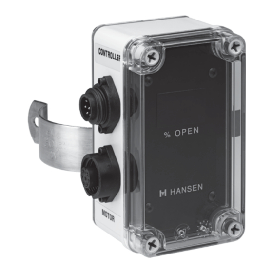
VPIF on Sealed Motor Valve
INTRODUCTION
The Valve Position Indicator, model VPIF is a digital
monitoring module added to the standard Sealed
Motor Valve (SMV) product line. The VPIF monitors
the valve position during normal operation and is
used to recalibrate the valve after service work is
performed.
T h e l a r g e L E D d i s p l a y a l l ow s f o r v i e w i n g o f
t h e va l ve p o s i t i o n ( i n p e r c e n t) d u r i n g n o r m a l
operation. The VPIF contains an internal independent
4 mA and 20 mA current source, which is switch
selectable for recalibr ation at the valve 0% 4
mA (closed) position and 100% 20 mA (full open)
position.
The VPIF can be mounted on or near the valve for ease
of use and visibility of the display. Often, valves are
mounted high in the air or in obstructive areas where
the technician cannot easily reach. The VPIF can be
mounted up to 10 feet (3 meters) in any direction from
the valve. VPIEC Extension Cables are available where
more length is required.
KEY FEATURES
Versatile installation options
Large LED display
Corrosion resistant enclosure, NEMA 4x
Simple SMV recalibration
Local indication of the SMV valve position
Uses same supply voltage as SMV
Allows for easy removal of the VPIF from the control
loop
Specifications, Applications,
Service Instructions & Parts
Valve Position Indicator
Standard Display Monitor
for use with
HMMV, HMMR, HMMVC, HMMRC,
HMXV and HMXVC
ADVANTAGES
In the normal operating mode the VPIF passes
the 4 to 20 mA current loop signals and 24V AC
to and from the SMV without signal degradation.
When used for recalibration, the VPIF will output
either 4 mA (fully closed) or 20 mA (fully open). A
waterproof 3 -position switch on the outside of
the VPIF enclosure is used for recalibration of
the SMV. The switch in the up position produces
20 mA; the switch in the down position produces a 4
mA signal to the valve. The calibration key must be
attached to the designated location on the side of the
SMV motor in order for the valve to recalibrate. After
recalibration, return the switch to the middle position
(automatic) and remove calibration key.
The VPIF valve position feedback can alert operators
to valves controlled by an unstable control scheme.
This feature is very important to the proper operation
of the refrigeration system and the life of the Sealed
Motor Valve. The VPIF is compact and reliable at
very low temperatures. Waterproof quick disconnect
connectors allow for easy removal of the SMV power
head for service.
APPLICATIONS
The VPIF may be installed on the following Sealed
Motor Valves:
H M M V, H M M R , H M M VC , H M M R C , H M X V a n d
HMXVC
Bulletin VPIFa
JUL 2006
VPIF
Advertisement

Related Manuals for Hansen VPIF

Summary of Contents for Hansen VPIF
- Page 1 (automatic) and remove calibration key. The VPIF can be mounted on or near the valve for ease The VPIF valve position feedback can alert operators of use and visibility of the display. Often, valves are to valves controlled by an unstable control scheme.
-
Page 2: Installation
The VPIF is shipped in a box with the Sealed Motor (90VA PER VALVE REQUIRED) Valve and comes factory calibrated and tested; ready to use. The VPIF can be mounted on the valve or to CABLE LENGTH ft(m) any flat surface. The clear cover must be removed to access the 4 plate bolts. - Page 3 VPIF. If the valve is not equipped mA. Move VPIF switch to up position. Maintain with a VPIF, then the 4 mA and 20 mA to calibrate must at least 20 mA for at least two minutes. This come from the computer or separate signal generator.
- Page 4 PLC. A 4-20 mA power supply internal 6. Assemble unit in reverse order. to the VPIF is used to power the feedback loop to the SMV. This allows for the valve percent open position to display on the VPIF LED display in both the automatic and recalibration operation.
- Page 5 MODEL: VPIF WIRING CUSTOMER SUPPLIED Figure D LINE VOLTAGE DC POWER CUSTOMER SUPPLIED TRANSFORMER SUPPLY 24VAC JUNCTION BOX 24VDC 90VA MIN 50 mA MIN PER VALVE PER VALVE SEE TABLE 1 YELLOW/GREEN STRIPE (GROUND) COMPUTER 24VAC (POWER) CONTROLLER 24VAC (POWER) –...
- Page 6 RETRO-FIT KITS FOR EXISTING SEALED MOTOR VALVE INSTALLATIONS Retro-fit Kits are available to add the VPIF to existing Sealed Motor Valve installations. Kit number 75-1210 includes the VPIF, cables and junction box with wire nuts. The VPIF is simply spliced into the existing wiring.
- Page 7 – Check signal polarity - #3 and #4, #5 and #6 wires No Valve Position Feedback – Cable connectors wired incorrectly – Check VPIF calibration switch in the NORMAL position – VPIF in the Local Feedback Mode – Check 24V AC supply power is good (+/-5%) No visual data on LED Display –...
-
Page 8: Warranty
CAUTION The VPIF is designed for use with the SMV only. Read these instructions and related safety precautions before selecting, using, or servicing these devices. WARRANTY Hansen electrical and electronic parts are guaranteed against defective materials and workmanship for 90 days F.O.B. our plant. All other components are guaranteed for one year F.O.B.
Need help?
Do you have a question about the VPIF and is the answer not in the manual?
Questions and answers