Table of Contents
Advertisement
Quick Links
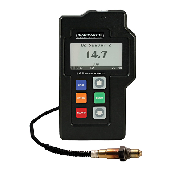
LM-2
Digital Air/Fuel Ratio Meter
User Manual
Note: This manual assumes that firmware version 1.10 or later is installed on your LM-2
Warning!
The Oxygen Sensor used in this device gets very hot in operation.
Do not touch the hot sensor. Do not let a hot sensor touch a combustible
surface. Do not use the sensor with or near flammable liquids or gases. Failure
to heed these warnings may result in severe burns, explosions or fires.
When installed in the exhaust, the oxygen sensor MUST be connected and
operating with the LM-2 whenever the car is running. An un-powered oxygen
sensor will be quickly damaged when exposed to hot exhaust gases.
Advertisement
Table of Contents
Troubleshooting

Subscribe to Our Youtube Channel
Related Manuals for Innovate LM-2

Summary of Contents for Innovate LM-2
- Page 1 LM-2 Digital Air/Fuel Ratio Meter User Manual Note: This manual assumes that firmware version 1.10 or later is installed on your LM-2 Warning! The Oxygen Sensor used in this device gets very hot in operation. Do not touch the hot sensor. Do not let a hot sensor touch a combustible surface.
-
Page 2: Table Of Contents
Single Cylinder Engines ......................... 39 Diesel Engines ..........................39 Sensor Timing Errors ........................40 Connecting the LM-2 to simulate a narrow band oxygen sensor ..........40 Attenuating a Tach Signal ......................42 OBD II connection diagnostic trace....................42 Appendix A: Specifications.......................... 43 Appendix B: Limited Warranty ........................ - Page 3 1 LM-2 The LM-2 is a single or dual channel wideband controller with a built-in OBD II scan tool, RPM input, four analog inputs, MTS serial I/O, SD memory card recording and two analog outputs per wideband channel. The following screens will help you get familiar with the unit.
- Page 4 SD Memory Card Slot USB Connector Bottom Sensor Input # 2 (Enabled with the Dual Channel version) Analog Cable Sensor Input # 1 Power OBD-II Connector Document # 31-0008 LM2_Manual_1.4.doc...
-
Page 5: Main Screen
1.1 Main Screen There are 5 different screen view options. These can be cycled by pressing the Mode button. One Channel Two Channels Four Channels One Channel Line Graph One Channel Fill Graph 1.2 Status Bar The bottom edge of the screen is the status bar and will look something like this: The left most portion is the current time (which can be set via menu and is set automatically by LM Programmer). - Page 6 - Reading Lambda (or AFR) - Error, Check Appendix E for error code meanings and trouble shooting tips Note: If the LM-2 is a single channel model, the second indication will be blank, not an error code. The next indicator, “R”, will appear when a) RPM is selected for logging/use (see menus) and b) an RPM signal is detected.
-
Page 7: Configuration Menu Screen
connector. Last, “H” indicates that the unit is the MTS head unit. If the unit is not head this indicator will appear as a “-“ 1.3 Configuration Menu Screen To enter the Configuration Menu Screen press and hold the Mode button. Navigating the Menu: “Enter”... -
Page 8: Recording
‘R’ and a counter on the lower left hand corner of the screen. To stop the record session press the Record button a second time. Note: Loss of power while the LM-2 is recording will lose all data from the current session being recorded. - Page 9 Note: While the session is being played back you can pres the Menu button to cycle through the different display screens and you may also press the Arrow buttons to change the displayed channels. 6. To stop the playback you may press the Cancel button at any time or allow the playback to run it’s course.
-
Page 10: Air/Fuel Ratio Setup
1. Connect the oxygen sensor to the provided sensor cable and then to the appropriate port on the LM-2. Note: The dual channel LM-2 model allows you to connect both oxygen sensors to the unit at the same time to do the calibration simultaneously. -
Page 11: Sensor Placement
Install the oxygen sensor’s bung upstream from the catalytic converter (a bung and plug is included in the LM-2 kit). The bung must be installed in the exhaust pipe at the side or on top, NOT on the bottom of the exhaust pipe. Any decent muffler or exhaust shop can do this for you. - Page 12 6 o’clock is the absolute worst position to mount the sensor. Wide band oxygen sensors, like the one shipped with the LM-2, are designed to work with unleaded gasoline. Use with leaded gasoline will significantly reduce the lifespan of the sensor.
-
Page 13: Calibration Schedule
2.3 Calibration Schedule Normally aspirated (daily driver) - Calibrate before installation of new sensor - Calibrate new sensor again after 3 month of use - Thereafter calibrate once a year or every 20,000 miles, whichever comes first Turbo Application, daily driver (tuned rich) - Calibrate before installation of new sensor - Calibrate new sensor again after 3 month of use - Thereafter calibrate twice a year or every 10,000 miles, whichever comes first... -
Page 14: Software (Logworks 3 And Lm Programmer)
1. Install the CD that came with your LM-2 in your personal computer. 2. The installer will automatically start, follow the prompts to install the software. 3. Connect one end of the USB cable to the LM-2 and the other end to your computer. 4. Power up the LM-2. -
Page 15: Updating Firmware
4. Once connected the LM Programmer will display the current version of the firmware that is installed in the LM-2. Do not update the firmware if the versions are the same. A firmware update should only be necessary if there has been a new release. -
Page 16: Downloading Logs From Memory Card
6. Select the firmware file with the dld extension. 7. The software will now prompt you to put the LM-2 in “Boot Mode.” In order to accomplish this you must power the unit off. Next, while pressing the Mode button on the LM-2, power the unit back ON. The LM-2’s display will show that it is now in “Boot Mode.”... - Page 17 4. A window will pop up which will allow you to select the desired log from the memory card. Click Open. Document # 31-0008 LM2_Manual_1.4.doc...
-
Page 18: Obd-Ii
4 OBD-II The LM-2 allows you to read up to 16 channels of “OBD-II” (“On Board Diagnostic) information directly from your vehicle’s engine control unit (ECU). A log file can be recorded on the included SD card, and played back on a personal computer using Innovate’s LogWorks software (included with the LM-2) or other 3rd party MTS-... -
Page 19: Selecting Channels On The Lm-2
4.2 Selecting Channels on the LM-2 1. Press and hold the Mode button to go into the Configuration Menu Screen. Select OBD-II and press the Enter button. 2. Select Configure OBD-II. 3. You will now be given the option to select a particular OBD II protocol or you can leave it on ‘Automatic’... -
Page 20: Selecting Channels With The Lm Programmer Software
4.3 Selecting Channels with the LM Programmer software 1. Connect the LM-2 to your computer with the provided USB cable. 2. Power up the LM-2. 3. The LM Programmer application can be launched from Start->Programs- >LogWorks3->LM Programmer from the Windows task bar. A small dialog box will appear indicating that the program is looking for connected Innovate Devices, then the main dialog should appear. -
Page 21: Obd-Ii Channel Speed
4.4 OBD-II Channel Speed The first is a log trace of one channel (RPM) from a 2001 Lexus: Notice that the data appears ‘steppy’ and, based on the timeline, appears to be updating about 6 times per second. Next we have a log trace of 16 channels (RPM, MAF, MAP, TP, you name it) from a 2006 Saturn: Document # 31-0008 LM2_Manual_1.4.doc... - Page 22 Even if we zoom in to a closer time scale, the data is quite smooth. Performance is controlled by two things: • The Connection Speed • ECU Responsiveness The Lexus in the first example is using ISO 9141 and 10.4K bits per second. The Saturn is using ISO 15765 (CAN) at 500K bits per second.
-
Page 23: Set The Priority Of Obd-Ii Inputs (Optional)
“Program”. The ECU will disconnect, reconnect with the new choices, and then the overall sample rate of the current settings can be observed using the blinking vehicle light on the LM-2. It is then up to you, the user, to decide what is an acceptable balance. - Page 24 So, reading those values less often means that values that do change quickly can be read more often. To understand how this works let’s take a look at how the LM-2 normally reads values: Read 1st...
- Page 25 With our racetrack shaped diagram fresh in mind, let’s look at Low Priority inputs in practice. In this example the vehicle can provide four LM-2 channels that update at full MTS rates. Even four channels are still very usable. For example, here is RPM,...
- Page 26 But not all channels change quickly and we are more concerned with some channels than others. For example, let’s say we are primarily concerned with RPM, SPARKADV, and FUEL1_OL. We’d like VSS, IAT, ECT, MAF, and MAP but we do not care if they update slowly.
-
Page 27: Check Vehicle Trouble Codes On The Lm-2
4.6 Check Vehicle Trouble Codes on the LM-2 1. To view your vehicle trouble codes press and hold the Mode button to go into the Configuration Menu Screen. -
Page 28: Check And Clear Vehicle Trouble Codes With Lm Programmer
3. Select Clear DTC Codes and press the Enter button. 4.8 Check and Clear Vehicle Trouble Codes with LM Programmer 1. Connect the LM-2 to the vehicle via the OBD II connector. 2. Power up the LM-2. 3. The LM Programmer application can be launched from Start->Programs- >LogWorks3->LM Programmer from the Windows task bar. -
Page 29: Obd Ii Basics
4.9 OBD II Basics OBD stands for “On Board Diagnostics”. It represents a collection of industry and legislative standards for getting basic diagnostic information from passenger vehicles sold in the US since Model Year 1996. The “II” means that this is the second attempt at standardizing across all makes and models. - Page 30 (ISO 15765 standard or extended) but that still leaves about 12 years of ‘compromise’ vehicles. Fortunately the LM-2 can take care of most of this complexity automatically. So, from a user’s point of view OBD-II can primarily be considered on the basis of what is consistent and standard, namely: •...
-
Page 31: Analog Cable
RPM – (Blue) 5.1 RPM Input The LM-2 has a direct tach signal input signal. This input can be used to feed a signal from the negative lead of a coil, ECU, negative lead of an injector, or ignition box (i.e. - Page 32 5. You will not have the option to select the ‘Polarity.’ Rising Edge is the most common way to measure a tach signal. If you find that your readings are very erratic you should change this setting to Falling Edge. Press Enter. 6.
- Page 33 Once the selection is made press Enter. You will be brought back to the main screen. Document # 31-0008 LM2_Manual_1.4.doc...
-
Page 34: Analog Inputs
5.2 Analog Inputs The LM-2 has 4 analog inputs for external 0-5V sensors. Each input has a corresponding positive lead (+) for the signal and a negative lead (–) for the ground signal source. It is important to wire both of these leads to get accurate measurements. -
Page 35: Analog Outputs
When programming by AFR the LM Programmer converts the number to Lambda before programming the LM-2. Click the ‘Program’ button to download the new data into the LM-2. Once the unit is programmed the ‘Program’ button will grey out. Document # 31-0008... -
Page 36: Advanced Output Programming
1/12 of a second. The factory default voltage output is set for 0 volts for both the Warm-up and Error Condition. When setting the LM-2 to the slower response speed settings the measured mixture data will be averaged over the response time setting before being output. -
Page 37: Wiring Analog Outputs
(-) must be connected to ground for the readings to be accurate. Below are the three different ways the analog outputs of the LM-2 can be wired. If you are unsure whether your analog input is differential or not you may wire the analog output as shown in diagram 1. -
Page 38: Tips, Tricks, & Troubleshooting
The Stoichiometric AFR value is the AFR multiplier. So for (standard, unblended) gasoline its 14.7. If you set it to 14.7 the LM-2 display will show 14.7 AFR for Lambda 1.0. If you set it to 6.4 (methanol) the LM-2 will show 6.4 AFR for Lambda 1.0. -
Page 39: General Measurement Requirements
Diesel Engines and gas turbines run at wide open throttle at all times. They do not have a throttle but regulate power by the amount of injected fuel. The LM-2 can still be used, but measurements at idle will read as lean. -
Page 40: Sensor Timing Errors
These errors are typically encountered when the sensor does not have outside air available as reference gas. If you encounter this error, restart the LM-2 and operate the sensor in free air (remove from exhaust.) If you still encounter this error, the sensor may be bad and needs to be replaced. - Page 41 To connect the LM-2 to the EFI-computer, first determine what kind of narrow band sensor is used, then follow the instructions below (you will need a digital multimeter to determine correct OEM sensor wires): a. Vehicle has a 1-wire sensor: Wire analog output 1 directly to the wire.
-
Page 42: Attenuating A Tach Signal
Wiring 1. Connect the tach signal to terminal A. 2. Connect terminal B to the tach signal input of the LM-2’s analog cable which is the Black wire with a White stripe. 3. Connect the terminal C to Ground. (Do not connect this to the Blue tach signal ground on the LM-2’s analog cable.) -
Page 43: Appendix A: Specifications
Appendix A: Specifications Power Power requirements Single Channel 8-14 Volt / 2 A (max, 1 A nominal) Dual Channel 8-14 Volt / 4 A (max, 2 A nominal) Serial Communication Serial Port Speed 19.2 kbit/sec Packet/Logging Speed 81.92 msec/sample packet Sample Resolution 10 bits (0..5V at 0.1% resolution) Software... -
Page 44: Appendix B: Limited Warranty
Innovate stands behind the quality of its products. Innovate makes the following warranty to purchasers of its products: All new Innovate products carry a six-month warranty from the date of purchase. If proof of purchase cannot be provided, warranty will be determined by date of manufacture. -
Page 45: Appendix C: Connectors
Notes: The “Alt CAN” Buss is for instrument monitoring and is not connected to the J1962 connector in the standard Innovate Cable. Also, the unit can be powered via this connector for basic operation. However, the O2 sensor circuits are not powered when OBD-II is used as the power source. - Page 46 Analog In 4 + Peach Analog Out 1 + Lime Green Analog Out 2 + Brown/White RPM + Black/White Note: All these inputs and outputs are “differential”. That is, the negative inputs must be connected to ground. 4. Serial Out 5.
-
Page 47: Appendix D: Supported Pids
Appendix D: Supported PIDs Name – Description Units Min. "RPM - Engine RPM", "RPM", 0.0, 10230.0, "TP - Throttle Position(abs)", "%", 0.0, 100.0, "LOAD_PCT - Engine Load(calc)", "%", 0.0, 100.0, "SPARKADV - Timing Advance(cyl1)", "degBTDC", -64.0, 63.5, "MAF - Mass Air Flow", "g/s", 0.0, 655.35,... - Page 48 "SHRTFT32 - O2 Fuel Trim 3-2", "%", -100.0, 99.22, "O2S41 - O2 Sensor(NB) 4-1", "Volts", 0.0, 1.275, "SHRTFT41 - O2 Fuel Trim 4-1", "%", -100.0, 99.22, "O2S42 - O2 Sensor(NB) 4-2", "Volts", 0.0, 1.275, "SHRTFT42 - O2 Fuel Trim 4-2", "%", -100.0, 99.22,...
-
Page 49: Appendix E: Error Codes And Troubleshooting Tips
2. Inspect sensor cable for rips or tears. 3. Damaged Sensor 3. Replace sensor Error 7 General System Software error Reboot LM-2 by cycling power. error (typically a Reload firmware if necessary. software error). Error 8 Sensor Timing 1. Sensor overheating. -
Page 50: Appendix F: Kit Contents
Appendix F: Kit Contents 1. USB Cable (P/N 3813) 2. LM-2 3. Bung and Plug** (P/N 3735) 4. O2 Sensor** (P/N 3737) 5. SD memory Card 6. Software CD 7. Sensor Cable** (P/N 3810) 8. OBD-II Cable (P/N 3809) 9. Analog Cable (P/N 3811) 10. - Page 51 Revision History 1.0 6/23/2008 Initial Release 1.1 7/10/08 Added RPM setup and LM Programmer configuration screens. 1.2 8/27/08 Added sections 6.8 (Attenuating a Tach Signal), 1.5 (Playback), 6.9 (OBD II connection diagnostic trace), and 3.3 (Downloading Logs from Memory Card). Added references for Inverse screen display in sections 1.3 and 1.4.
Need help?
Do you have a question about the LM-2 and is the answer not in the manual?
Questions and answers