
Subscribe to Our Youtube Channel
Summary of Contents for Kentec Electronics K25000 Series
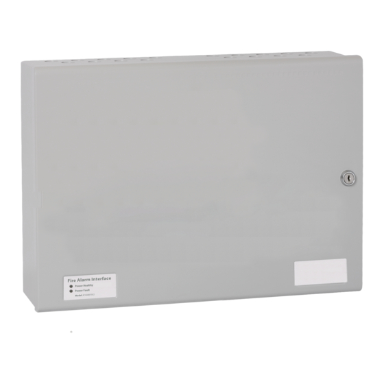
- Page 1 K25000 & KD25000 Series Fire Alarm Power Supplies Installation, Commissioning and Operating Manual Man-1128 Issue 15 October 2019 Page 1 of 20 Man-1128_K25400_series_Power_Supply_Manual_15...
-
Page 2: Table Of Contents
Section Page 1. General ........................... 3 2. Power Requirements ......................... 3 2.1 Input/Output Electrical Ratings ........................ 3 2.2 Fuse Ratings ............................3 2.3 Batteries ............................... 3 3. Installation ..........................4 3.1 Environmental Considerations ......................... 4 3.2 Mounting .............................. 4 3.3 Connecting to the mains Input ......................... 5 3.4 Connecting to the Outputs ...................... -
Page 3: General
1. General The K25000 series are combined power supply and battery chargers designed to be used for fire alarm control and indicating equipment complying with EN54-2 and EN54-4. K25400 models are fitted with a 5.25A power supply and K25250 models are fitted with a 2.5A power supply. -
Page 4: Installation
Any instructions specifically advised by the manufacturer (iv) 3.1 Environmental Considerations The KD25000 and K25000 series power supplies are mounted in steel enclosures with an ingress protection rating of IP30.The operating temperature range should not exceed -5°C to +40°C (±2°).Humidity levels should not exceed 95% (non-condensing). -
Page 5: Connecting To The Mains Input
3.3 Connecting to the mains Input Do not connect a mains supply unless the supply voltage matches that shown on the rating plate. A minimum cable size of 0.75mm must be used. Maximum cable size is 4.0mm². Fit the mains cable via a suitable 94HB flame rated cable gland via a knockout close to the power supply unit. Connect the Neutral of the mains power supply to the terminal marked N, connect the Live of the mains power supply to the terminal marked L and connect the earth to the terminal marked E. -
Page 6: Connecting To The Outputs
Pin 12 = Earth fault (switched –ve 100 milliamps max) Pin 13 = Charger fault (switched –ve 100 milliamps max) When used in the K25000 series boxed power supplies, the load connection terminals (detailed in 3.4.1 above) must be used as the primary power connection. -
Page 7: Load Connections (Optional Dual Transmission Path Pcb Fitted)
3.4.3 Load connections (optional dual transmission path PCB fitted) When the power supply unit is being used to supply power to fire alarm control and indicating equipment, to comply with the requirements of EN54-4, there must be two transmission paths from the power supply to the control panel in order that a short or open circuit in one transmission path will enable the control panel to be supplied with power from the other. -
Page 8: Fault Output Contact Connections
3.4.5 Fault output contact connections A volt free contact rated at 30V DC and 1 Amp is available for connection to other systems. This contact will operate upon any of the fault conditions listed in section 4. The contact positions shown here are with mains and battery connected and with no fault conditions on the power supply. -
Page 9: Disabling Battery Disconnected Indication
In order to correctly charge the batteries, the power supply must be matched to the type of batteries that are connected to it. This is done by setting the DIP switch located next to the ribbon cable connector J5. Switch 4 is to choose the battery manufacturer (Yuasa or Powersonic). -
Page 10: Indicators
4. Indicators The diagnostic indicators visible through the case of the power supply indicate the status of the unit as follows: DC OUT ON – The 24V DC output is supplying power to the load. HEARTBEAT (flashing slowly) – The processor is functioning normally. -
Page 11: Maintenance
Batteries with a manufacturing date older than 6 months are not recommended for use with this equipment. Sealed lead acid batteries can liberate hydrogen during normal use. The KD25000 and K25000 series of power supplies have adequate ventilation to allow this hydrogen to disperse normally and safely therefore additional sealing or mounting inside a sealed enclosure is prohibited. -
Page 12: Power Supply Unit Dimensional Drawings
8. Power Supply Unit Dimensional Drawings 385mm 90mm 285mm POWER ON POWER FAULT KD 25250M2, and KD25250M2 385mm 110mm 520mm POWER ON POWER FAULT KD25250M3, KD25400M3, K25250M3 and K25400M3 Page 12 of 20 Man-1128_K25400_series_Power_Supply_Manual_15... - Page 13 500mm 105mm 355mm POWER ON POWER FAULT KD2540003, KD2525003, K2540003 and K2525003 500mm 190mm 400mm POWER ON POWER FAULT KD2540015 and K2540015 Page 13 of 20 Man-1128_K25400_series_Power_Supply_Manual_15...
-
Page 14: Temperature Sensor Mounting
9. Temperature sensor mounting To achieve correct battery charging temperature compensation (essential for correct maintenance of batteries) the flying lead thermistor must be affixed to one of the batteries using Scotch 27 Glass Cloth Electrical Tape or equivalent. A suitable piece of this tape is supplied holding the temperature sensor to the power supply chassis. Remove tape holding temperature sensor to power supply chassis and use it to fit the temperature sensor to one of the batteries roughly in the position shown below... -
Page 15: Cabling
10. Cabling Mains The Mains cable should be a minimum cable size of 0.75mm² and rated at 250V. A suitable primary disconnecting device must be provided in the end use application. Maximum cable size is limited to 4mm². Keep all mains wiring separate from the Extra Low Voltage (ELV) battery cables and power supply output cables Extra Low voltage wiring Cable for low voltage wiring should be a minimum size of 1.0mm and rated for at least 30V DC. -
Page 16: Mains Voltage Selection
11. Mains Voltage Selection The K25000 series power supplies will be supplied as 240V input voltage selected as standard, but may be optionally supplied as 110V if requested when the power supply was ordered. The selected voltage of the power supply is clearly shown on the power supply cover. - Page 17 15) Modify the input voltage selection on the power supply cover to show the correct input voltage for the power supply Note: When the power supply is removed from the panel enclosure, it is possible to view the link location on the circuit board through an aperture in the outer cover at the top of the power supply.
- Page 18 Page 18 of 20 Man-1128_K25400_series_Power_Supply_Manual_15...
- Page 19 Page 19 of 20 Man-1128_K25400_series_Power_Supply_Manual_15...
- Page 20 *Man-1128* Page 20 of 20 Man-1128_K25400_series_Power_Supply_Manual_15...
Need help?
Do you have a question about the K25000 Series and is the answer not in the manual?
Questions and answers