
Subscribe to Our Youtube Channel
Related Manuals for REPLIGEN XCell C410:V3

Summary of Contents for REPLIGEN XCell C410:V3
- Page 1 XCell™ C410:V3 Controller User Guide For use with: • XCell ATF® 4 Device • XCell ATF® 6 Device • XCell ATF® 10 Device UG-C410v3-06...
- Page 2 Customer shall refer to the terms and conditions of sale governing the transaction for any and all warranties for the Product. Repligen Corporation shall not be liable for errors contained herein or for incidental or consequential damages in connection with the furnishing, performance, or use of this material.
-
Page 3: Table Of Contents
User Guide XCell™ C410:V3 Controller User Guide KrosFlo® TFDF™ Lab System Contents 2.1.1 Filtration assembly ...................... 14 4.3.1 S-Line HFM insertion ....................43 4.3.2 I-Line HFM insertion ....................43 7.4.1 Bi-annual maintenance ....................48 7.4.2 Every four years ......................49 UG-C410v3-06... - Page 4 User Guide XCell™ C410:V3 Controller User Guide KrosFlo® TFDF™ Lab System UG-C410v3-06...
- Page 5 User Guide XCell™ C410:V3 Controller User Guide KrosFlo® TFDF™ Lab System List of tables Table 1. XCell ATF® pump housing and controller pairings .............. 10 Table 2. Utility requirements ......................12 Table 3. Size and weight ........................13 Table 4. Primary screen information ....................
- Page 6 User Guide XCell™ C410:V3 Controller User Guide KrosFlo® TFDF™ Lab System Abbreviations Alternating tangential flow Driving force Driving pressure Hollow fiber filter module Human machine interface Pump air Pump liquid Pressure regulator valve Screen module SUBs Single-use bioreactors TFDF® Tangential flow depth filtration California Proposition 65 Warning WARNING This product can expose you to chemicals including Cadmium, which is...
- Page 7 That connection can be hard piped or soft piped. Either one may be used to make a sterile connection between vessel and the filtration assembly, as will be discussed further on. repligen.com UG-C410v3-06...
-
Page 8: Figure 1. Filtration Assembly Connection To C410:V3 Controller And A Bioreactor Side Port
HFM (lumen side), to the PL chamber, generating tangential flow in the other direction. This pumping phase (or cycle) is called the exhaust cycle. These alternating pump cycles are then repeated continuously. See also Figure repligen.com UG-C410v3-06... -
Page 9: Figure 2. Xcell Atf® Device Pump Cycles
In the case a diaphragm fails, the air flow into the diaphragm pump will proceed through the HFM or SM into the vessel. A free exhaust from the vessel will minimize the buildup of pressure in the vessel. repligen.com UG-C410v3-06... -
Page 10: Table 1. Xcell Atf® Pump Housing And Controller Pairings
XCell™ C410:10V3-GMP Device with air tubing, standard GMP documents and Stainless Steel and FAT. Single-use Profibus configured XCell™ C410-V4B Controller with XCell™ C410:10V4B-GMP power separation for XCell ATF® 10 Device with air tubing and standard GMP documentation and FAT. repligen.com UG-C410v3-06... -
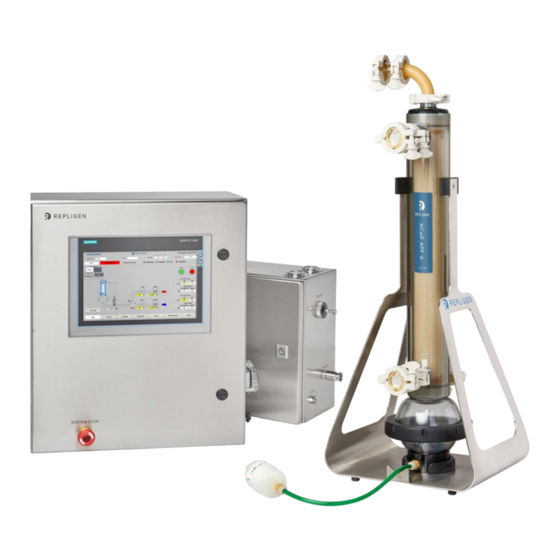
Page 11: Figure 3. Xcell™ C410:V3 Controller, Xcell Atf® 10 Ss Pump Housing And Pressure Relief Valve
User Guide XCell™ C410:V3 Controller 1.3 XCell ATF® Device interconnectivity drawing Figure 3. XCell™ C410:V3 Controller, XCell ATF® 10 SS pump housing and pressure relief valve repligen.com UG-C410v3-06... -
Page 12: Table 2. Utility Requirements
6.1 bar Secondary pressure Typically: 35 psi / 2.4bar, Regulated oil free, dry, filtered air Vacuum supplied by a Repligen or customer supplied local pump capable of maintaining ~- 12.5 psig with nominal flow as follows: Vacuum service Minimum -12.5 psig XCell ATF®... -
Page 13: Table 3. Size And Weight
XCell ATF® 10 SS Pump Housing ~40 kg XCell ATF® 6 Single-use Device ~ 5 kg Does not include the weight of liquid and A2B connectors XCell ATF® 10 Single-use Device ~ 18 kg repligen.com UG-C410v3-06... -
Page 14: Filtration Assembly
Vacuum gauge (0 to -14psi, o to -0.95 bar) Pressure gauge (0 to 60psi, 0 to 4.1 bar (Not pictured in Figure13) Pressure relief assembly - set to 40 psi, 2.8 bar. Electric enclosure The Electric enclosure contains the HMI and PLC components, including: repligen.com UG-C410v3-06... -
Page 15: Figure 5. Electric Box (E-Box) Connections
WARNING: Do not exceed 90 psi / 6.1 bar on the Air inlet. Exhaust/ vacuum line (f) - Located on the P-Box. This line is connected to a vacuum source. A vacuum source should always be connected to the exhaust line to ensure reliable operation of the repligen.com UG-C410v3-06... - Page 16 PROFIBUS Organization and is standard Ethernet (IEEE802.3). The Profinet® communication protocol sends and receives data using the open Ethernet TCP/IP standard at a bandwidth of 100 Mbit/s and functions identical to traditional industrial Ethernet in providing “real-time” channel for time-critical communications (i.e. process data). repligen.com UG-C410v3-06...
- Page 17 XML. Proceed to Appendix 6 for details on OPC Integration for Remote Data Logging. 2.6 Disconnecting the controller 1. The controller must stay connected to the power supply in order to function. repligen.com UG-C410v3-06...
-
Page 18: Table 4. Primary Screen Information
Graphical real time display of flow set point, exhaust set points, flow process value, TRENDING vessel weight. BATCH INFO Batch Set-up screen ADMINISTRATOR Setting of users ID, security level and passwords, close application, PLC ON/OFF LOG OFF Users log off repligen.com UG-C410v3-06... -
Page 19: Figure 6. Log On Screen
Log on screen appears when the C410:V3 controller is powered up. Click on LOG ON to bring up User/Password Dialog Box and Keyboard. For first time use, enter ADMIN for USER and 1234 for PASSWORD. Figure 7. Log on screen and password repligen.com UG-C410v3-06... -
Page 20: Figure 8. Main Screen
6. Monitor Overtime condition- displayed in FLOW status sub screens, by change of actual cycle time field to red. 7. Monitor Overflow condition- displayed in FLOW status sub screens, by change of actual cycle time field to orange. repligen.com UG-C410v3-06... -
Page 21: Table 5. Main Screen Display Parameters
Press to STOP diaphragm pump P2 Trend Button Display Press to Hide / Reveal the P2 Trending Screen All Primary screen buttons are displayed to navigate to those screens. All Primary Button Display Alarms, Trending, Batch Info, Set-up, Administration repligen.com UG-C410v3-06... - Page 22 From the Set-up Screen, an Engineer/Administrator can make entries in the following: • Basic Set-up screen • Advance Set-up screen • Calibration screen • Help Guide Exit to Primary screens • • Navigate to the following secondary screens repligen.com UG-C410v3-06...
-
Page 23: Figure 9. Basic Set-Up Screen
Figure 9. Basic Set-up screen From the Basic Set-up screen, an Engineer/Administrator can: • Set initial controller Set-up Change Hi and Lo Alarm set points • • Change Process Parameters • Access other screens based upon password security levels repligen.com UG-C410v3-06... -
Page 24: Table 6. The Basic Set-Up Screen Display Parameters
Accept or Discard change to accept/reject parameter change on the screen. Accept/Discard change All Primary All Primary screen buttons are displayed to navigate to those screens Slope Function Enable: Don’t enable this function unless you thoroughly understand its effects. repligen.com UG-C410v3-06... -
Page 25: Table 7. Advanced Set-Up Screen Display Parameters
Minimum operating limit for PV2 (%) PRV1 Max (psi) Maximum operating limit for PRV1 (psi) PRV1 Min (psi) Minimum operating limit for PRV1 (psi) PRV2 Max (psi) Maximum operating limit for PRV2 (psi) PRV2 Min (psi) Minimum operating limit for PRV2 (psi) repligen.com UG-C410v3-06... -
Page 26: Table 8. The Start-Up Guide Screen Display Parameters
Ethernet configuration, only accessible to the Administrator, the Ethernet configuration allows the administrator to set up the communication interface of the HMI and PLC units. Note: The HMI must be set through the set connection function in windows light to the PLC address for proper communication to occur. repligen.com UG-C410v3-06... -
Page 27: Table 9. Calibration Screen Display Parameters
Administrator and Engineer will be able to configure the Engineering Units, the Minimum Engineering Value, the Maximum Engineering Value, and perform a two-point calibration. Note: this should only be performed by a qualified metrology personal or Repligen Field Service Engineer. -
Page 28: Figure 13. Trending Screen
Accept Change and Discard Change to accept or reject any parameter change on Accept/Discard change the screen. All Primary All Primary Screen Buttons are displayed to navigate to those screens. Figure 13. Trending screen The Trending screen displays an Overview screen from where the following trends are selected. repligen.com UG-C410v3-06... -
Page 29: Table 10. Lpm Min/Max
Zooms out of the displayed time section Scrolls back one display width Scrolls forward one display width Starts or continues trend recording Stops trend recording Primary screens All Primary screen buttons are displayed to navigate to those screens. repligen.com UG-C410v3-06... -
Page 30: Figure 15. Pv, Prv, P2, P3, P4, P5, W1 Trend Screens
Figure 15. PV, PRV, P2, P3, P4, P5, W1 Trend screens These screens monitor, in real time, the specific analog signal. Trend buttons select trend to display. All screens have the following screen control options listed in Table repligen.com UG-C410v3-06... -
Page 31: Figure 16. Alarm Screen
Warnings/Alarms will activate the audible horn located inside XCell™ C410:V3 Controller cabinet. An Alarm condition will automatically stop the pump cycling action, while a Warning condition allows the pumping cycling action to continue. Warning and Alarm conditions are described in the following section. repligen.com UG-C410v3-06... -
Page 32: Table 12. The Alarm Screen Display Parameters
Flow Set Point cannot be reached. P-Flow Regulator (PV1) below minimum operating setting. • Exhaust Set Point cannot be reached. E-Flow Regulator (PV2) above maximum operating setting. • Exhaust Set Point cannot be reached. E-Regulator (PV2) below minimum operating setting. repligen.com UG-C410v3-06... -
Page 33: Figure 17. Users Screen
Each User ID includes a field for Log off Time (in minutes). When the time setting is reached, the current user will automatically be logged off. Access to other screens will prompt the user to log in again. To disable this feature, a time value of 0 can be entered into the Log off time field. repligen.com UG-C410v3-06... -
Page 34: Table 15. Administration Screen Display Parameters
The controller must be in the standby mode. Do not turn the Sol. Force to the On position when the XCell ATF® Device is connected to the P-Box (with air pressure utility). Doing so may over expand the diaphragm causing potential blowout. repligen.com UG-C410v3-06... -
Page 35: Table 16. Batch Information Overview Screen Display Parameters
Click on field to change batch name Button Description Cycle Count - Reset Resets cycle count to zero in Batch Data field Algorithm Navigates to Batch Algorithm screens All Primary All Primary screen buttons are displayed to navigate to those screens repligen.com UG-C410v3-06... -
Page 36: Table 17. Batch Info Algorithm Display Parameters
Shows cycle count triggered by overflow, tracks pressure cycle and Exhaust Overflow cycle counts Button Description Reset count Resets all counts, by Set Point, Overtime and Overflow to zero Overview Navigates to Batch Overview screens All Primary All Primary screen buttons are displayed to navigate to those screens repligen.com UG-C410v3-06... - Page 37 Based on an entered set point in either Liters per minute, LPM, or time, in seconds, the XCell™ C410:V3 Controller will continually adjust the pressure and exhaust flow rates to match the entered set point flow rate. repligen.com UG-C410v3-06...
-
Page 38: Figure 21. Instrument Flow Control Schematic Of Xcell™ C410:V3 Controller
• Regulated air pressure set to 35 psi Vacuum source connected • Following Log On and entry of Batch Information, go to the Set-up screen. Go to the Basic Set Up screen, and enter the following field values: repligen.com UG-C410v3-06... -
Page 39: Table 18. Batch Set-Up Screen Values
XCell ATF® 10 XCell ATF® 10 User Set point range Device Device Legacy Device Device Max P-Flow (LPM) Min P-Flow (LPM) Max E-Flow (LPM) Min E-Flow (LPM) PV1 Max (%) PV1 Min (%) PV2 Max (%) PV2 Min (%) repligen.com UG-C410v3-06... -
Page 40: Table 20. Field: P-Flow And E-Flow Values
The XCell ATF® Device process control settings will depend on the process requirements. Each user or process may have its own unique requirements. Hopefully, the example provides a guideline, to assist the users, in selecting and optimizing operating conditions. repligen.com UG-C410v3-06... - Page 41 Using a vessel that cannot be pressurized, both pressure and vacuum services are needed. See Utility requirements, Table Repligen offers custom, disposable connections to most commercial SUBs. The connection procedure between the filtration assembly and vessel are provided separately. Start 1.
- Page 42 XCell™ C410:V3 Controller provides relay outputs on the E-Box for activating or deactivating a filtrate / harvest pump. Contact Repligen for system specific instructions. 4. Hollow fiber module and diaphragm replacement The following is a guideline for replacing a Hollow Fiber Module (HFM) or the diaphragm within the diaphragm pump.
-
Page 43: S-Line Hfm Insertion
6. On the other end of the filter housing, place the second “O” ring into the formed groove between HFM and housing end-ferrule. 7. Carefully place the filter housing onto the diaphragm pump, forcing the “O” ring deeper into the groove. 8. Clamp the filter housing to the diaphragm pump. repligen.com UG-C410v3-06... - Page 44 9. Assemble the XCell ATF® Device. 4.4 Screen Module replacement instructions. If the SM is being used, contact Repligen for replacement 4.5 Diaphragm replacement Replacement or placement of a diaphragm within the diaphragm pump is part of the diaphragm pump assembly process which differs slightly among the XCell ATF® 4 Device, XCell ATF® 6 Device, and XCell ATF®...
- Page 45 Repligen recommends sterilization of the filtration assembly by autoclaving. An appropriately sized autoclave is required. Contact Repligen for dimensional analysis of the autoclave. Sterilization of the filtration assembly by autoclaving is one of the simplest methods to sterilize the system.
-
Page 46: Figure 23. Filtration Assembly Prepared For Autoclaving
- 3 moderated prevac pulses to control the rate of temperature change within the cartridge to a rate of 1° C/min during the warmup. Repligen recommends that during the cycle development, several thermocouples should be positioned within the assembly to track the rate of temperature change and confirm that all positions are at 121 - 123 °... - Page 47 7. Securely connect a regulated steam source to the steam inlet valve. 8. Open steam service. 9. Slowly open steam inlet valve. 10. Slowly open steam condensate valve. 11. Sterilize connection for about 20 min. at 121° C and ~16 psi. 12. Cool-down. 13. Close the condensate valve. repligen.com UG-C410v3-06...
-
Page 48: Bi-Annual Maintenance
The O-rings on the ventilation ports and quick connects (XCell ATF® 4 Device and XCell ATF® 6 Device) should be replaced every two or three runs. Replacement kits are available from Repligen. HFM Filter “O” rings should be replaced with each new filter. For pump line, air supply, and vacuum source, all “O”... -
Page 49: Every Four Years
XCell ATF® 10 Device Device Device Legacy Device Device Pump volume (L) Cycle time (sec) Flow rate (L/min) 18.8 76.5 90.0 12.5 51.0 60.0 38.3 45.0 30.6 36.0 25.5 30.0 21.9 25.7 19.1 22.5 17.0 20.0 15.3 18.0 repligen.com UG-C410v3-06... -
Page 50: Table 22. Access Levels To The Xcell™ C410:V3 Controller
General adjust Min and Max View and allowed to P4 Trend General adjust Min and Max View and allowed to P5 Trend General adjust Min and Max View and allowed to WI Trend General adjust Min and Max repligen.com UG-C410v3-06... - Page 51 View only General General Silence alarm General Allowed Alarms Clear alarm General Not allowed View and allowed to Overview General adjust Min and Max Trending View and allowed to Process Trend General adjust Min and Max repligen.com UG-C410v3-06...
- Page 52 Pressure Offset Allowed to adjust Allowed to adjust Delay time pressure and exhaust cycle fields Allowed to adjust Pump Parameters Over time pressure and exhaust cycle fields Allowed to adjust PV Step size pressure and exhaust cycle fields repligen.com UG-C410v3-06...
- Page 53 1st Point Not allowed Analog Input P2 Eng units Not allowed 2nd Point Not allowed Actual Value Not allowed Allowed (No Accept changes occur) Select Allowed Eng Units Not allowed 2nd Point Not allowed Eng Units Not allowed repligen.com UG-C410v3-06...
- Page 54 Select Allowed Eng Units Not allowed 7th Point Not allowed Eng Units Not allowed Analog Input W1 8th Point Not allowed Actual Value Not allowed Allowed (No Accept changes occur) Help General Access View only Allowed repligen.com UG-C410v3-06...
- Page 55 View and allowed to WI Trend General adjust Min and Max Name View Only Batch Data Elapsed time View Only Cycle count View Only Batch Info- User ID View Only overview Batch Setup Name Allowed Reset Allowed General access General Allowed repligen.com UG-C410v3-06...
- Page 56 Eng Units Allowed Admin Analog Input P2 1st Point Allowed Eng Units Allowed 2nd Point Allowed Calibration 1 Actual Value View only Accept Allowed Select Allowed Analog Input PRV1 Eng Units Allowed 2nd Point Allowed Eng Units Allowed repligen.com UG-C410v3-06...
- Page 57 Allowed Actual Value View only Accept Allowed Select Allowed Eng Units Allowed Analog Input P5 6th Point Allowed Eng Units Allowed 7th Point Allowed Actual Value View only Accept Allowed Select Allowed Eng Units Allowed 7th Point Allowed repligen.com UG-C410v3-06...
- Page 58 General access General access Allowed Admin Allowed for all User except Admin and PLC User Allowed for all Admin-Users User Password except Admin and Password/Maintenance PLC User Allowed for all Group except for PLC User Log off time Allowed repligen.com UG-C410v3-06...
- Page 59 User Guide XCell™ C410:V3 Controller 10. Appendix 3: General Information and Handling Instructions Repligen XCell ATF® System is rated for acceptable sound levels (60 dBA) • • Weight of C410 controller: E-Box 23 kg (50 lbs), P-Box 13 kg (28.6 lbs) Complete system visual inspection for damage or potential risk to the operator, surrounding •...
- Page 60 To protect the XCell ATF® Device housings and devices from reaching pressures > 40 psig, a pressure relief assembly set at 40 PSIG is located on the outlet of pneumatic box supplying pressure and vacuum to the air-side hemisphere of the pump housing. The flow path of pressure relief is shown below. repligen.com UG-C410v3-06...
- Page 61 Press save to set the connection. “Save is successful” appears at the bottom of the window. o. Close the window to exit. p. Close the Service and Commissioning window. q. Close the Settings Window 4. Start the program again and ensure that ‘####’ do not appear in the main screen fields. repligen.com UG-C410v3-06...
-
Page 62: Table 23. Monitor Points List
Fill Cycle Time ETIMEVAL DInt %DB1.DBD126 Exhaust Cycle Time STATUSREG Word %DB1.DB130 Pump Status Register E_ERROR Real %DB1.DBD134 Set point deviation error Flow Driving Force Offset for FDFOFST Real %DB1.DBD174 switching Exhaust Driving Force Offset for EDFOFST Real %DB1.DBD178 switching repligen.com UG-C410v3-06... - Page 63 P2 Exhaust Cycle Slope Total Bioreactor_Backpressure Real %DB1.DBD914 Bioreactor Backpressure Model_Num_HMI %DB1.DBW918 Model Number SP Height_Differential %DB1.DBW928 Height Differential SP Press_Cycle_Delay_Time_SP %DB1.DBW930 Pressure Cycle Delay Time SP Press_Cycle_Over_Time_SP %DB1.DBW932 Pressure Cycle Over Time SP Vac_Cycle_Over_Time_SP %DB1.DBW936 Vacuum Cycle Over Time SP repligen.com UG-C410v3-06...
-
Page 64: Table 24. Input/Output List
System Fault %Q0.1 Warning Horn Pump Inflate/Defl SOL1 %Q0.2 Solenoid Pump Controller %Q0.3 Status Relay #1 Pump Controller %Q0.4 Status Relay #2 Pump Interlock %Q0.5 Relay #3 Pump Interlock %Q0.6 Relay #4 System Stop %Q0.7 Indicator Spare Spare repligen.com UG-C410v3-06... - Page 65 Pressure 5 Optional RAW_W1_PV_1 %IW110 Note 1 Weight Inflation RAW_PRV1_CV_1 %QW128 0-100 Pressure Deflation RAW_PRV2_CV_1 %QW130 0-100 Pressure Inflation RAW_PV1_CV_1 Pressure %QW132 0 - 40 Proportional Deflation RAW_PV2_CV_1 Pressure %QW134 -15 - 0 Proportional Note 1: Depends on calibration. repligen.com UG-C410v3-06...
-
Page 66: Table 25. Alarm List
P2_PV <= P2 Lo Set Point Warning, P2 Pressure below %DB1.DBX Pump is Pressure Alarm Delay in Activate "DB1".WARN_REG(4) Lo Limit 132.0 Running Alarm Lo 10ms System Fault Setpoint increments. Warning Horn Note 1: Depends on calibration. repligen.com UG-C410v3-06... -
Page 67: Table 26. Spare Parts
ASSEMBLY, 3 way valve- SOL1 for C410v2 XCell™ 10 Controllers C410:P-KN-PR-0-60 REGULATOR 0-60PSI 1.5" Vacuum gauge 0-30"Hg CENTER BACK 1/8" NPT,7216-1½-1/8 30/0 C410:P-1.5VG FLANGE MOUNT-replaces C410:P-MF-PG-0-30FM 1.5" PRESSURE GAGE 0-60PSI CENTER BACK 1/8" NPT, 7216-1½-1/8 0-60 C410:P-1.5PG FLANGE MOUNT-replaces C410:P-MF-PG-0-60FM C410-P-KN-PR-40-420-P10 PRV assembly replacement part repligen.com UG-C410v3-06... - Page 68 ASME clamp w/ relief, assembly, XCell ATF® 10 Device A10:C1-LOCK-A C clamp w/ Lock-A, assembly, XCell ATF® 10 Device A10:C1-LOCK-B C clamp w/ Lock-B, assembly, XCell ATF® 10 Device SG-05-E Sanitary gasket, 1/2" TC SG-075-E Sanitary gasket, 3/4" TC SG-1.5-E Sanitary gasket, 1 1/2" TC repligen.com UG-C410v3-06...
- Page 69 A:ST-TS, thumb screw for XCell ATF® 10 Device base XCell ATF® 10:AIR-ASSY Air inlet assembly, XCell ATF® 10 Device XCell ATF® 10:PH-AA-AIR Air hemisphere, XCell ATF® 10 Device w/ XCell ATF® 10 Device :AIR-ASSY P3-CPM1.5-TC3/4 Kit, PT, 1.5"CPM fitting, 3/4"TC repligen.com UG-C410v3-06...
Need help?
Do you have a question about the XCell C410:V3 and is the answer not in the manual?
Questions and answers