Table of Contents
Advertisement
Quick Links
Advertisement
Table of Contents

Related Manuals for ASROCK Z790M-ITX WiFi


Summary of Contents for ASROCK Z790M-ITX WiFi
- Page 2 Contact Information If you need to contact ASRock or want to know more about ASRock, you’re welcome to visit ASRock’s website at http://www.asrock.com; or you may contact your dealer for further information. For technical questions, please submit a support request form at https://event.asrock.com/tsd.asp...
-
Page 3: Table Of Contents
Chapter 1 Introduction Package Contents Specifications Motherboard Layout I/O Panel Block Diagram 802.11ax Wi-Fi 6E Module and ASRock WiFi 2.4/5/6 GHz Antennas Chapter 2 Installation Installing the CPU Installing the CPU Fan and Heatsink Installing Memory Modules (DIMM) Connecting the Front Panel Header... - Page 4 2.14 M.2 SSD Module Installation Guide (M2_1 and M2_2) 2.15 Change Screen Brightness for eDP in Windows®...
-
Page 5: Chapter 1 Introduction
If you require technical support related to this mother- board, please visit our website for specific information about the model you are using. You may find the latest VGA cards and CPU support list on ASRock’s website as well. ASRock website http://www.asrock.com. -
Page 6: Specifications
1DPC 2R Up to 5200+ MHz (OC), 5200 MHz Natively. • Max. capacity of system memory: 64GB • Supports Intel® Extreme Memory Profile (XMP) 3.0 * Please refer to Memory Support List on ASRock's website for more information. (http://www.asrock.com/) Expansion CPU: • 1 x PCIe 5.0 x16 Slot (PCIE1), supports x16 mode*... - Page 7 Z790M-ITX WiFi • Intel® X Graphics Architecture (Gen 12) • 1 x eDP 1.4, supports max. resolution up to Full HD 60Hz • 1 x HDMI 2.1 TMDS Compatible, supports HDCP 2.3 and max. resolution up to 4K 60Hz • 1 x DisplayPort 1.4 with DSC (compressed), supports HDCP 2.3 and max.
- Page 8 Rear Panel • 2 x Antenna Ports • 1 x HDMI Port • 1 x DisplayPort 1.4 • 1 x Optical SPDIF Out Port • 4 x USB 3.2 Gen2 Type-A Ports (10 Gb/s) • 1 x USB 3.2 Gen2x2 Type-C Port (20 Gb/s) • 1 x USB 2.0 Port • 2 x RJ-45 LAN Ports • 1 x Line Out Jack (Gold Audio Jack)
- Page 9 • ErP/EuP ready (ErP/EuP ready power supply is required) * For detailed product information, please visit our website: http://www.asrock.com Please realize that there is a certain risk involved with overclocking, including adjusting the setting in the BIOS, applying Untied Overclocking Technology, or using third-party overclocking tools.
-
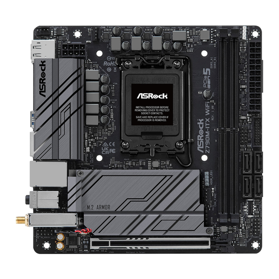
Page 10: Motherboard Layout
1.3 Motherboard Layout Top Side View RGB_LED1 CPU_FAN1/WP CHA_FAN1 RoHS BIOS USB 3.2 Gen2 T: USB32_1 B: USB32_2 USB_2_3 Intel Z790 F_USB32_TC_1 CHA_FAN2 M2_WIFI CLRMOS1 PANEL1 HD_AUDIO1 AUDIO CODEC PCIE1... - Page 11 Z790M-ITX WiFi Back Side View...
- Page 12 No. Description CPU/Water Pump Fan Connector (CPU_FAN1/WP) ATX 12V Power Connector (ATX12V1) Chassis Fan Connector (CHA_FAN1) 2 x 288-pin DDR5 DIMM Slots (DDR5_A1, DDR5_B1) RGB LED Header (RGB_LED1) ATX Power Connector (ATXPWR1) USB 2.0 Header (USB_2_3) USB 3.2 Gen1 Header (USB32_5_6) SATA3 Connector (SATA3_1) SATA3 Connector (SATA3_0) SATA3 Connector (SATA3_3)
-
Page 13: I/O Panel
Z790M-ITX WiFi 1.4 I/O Panel No. Description No. Description DisplayPort 1.4 USB 3.2 Gen2 Type-A Port (USB32_4) LAN RJ-45 Port (Intel® I219V)* USB 3.2 Gen2x2 Type-C Port 2.5G LAN RJ-45 Port (USB32_TC1) (Intel® I226V)** USB 2.0 Port (USB_1) Microphone Input Jack*** USB 3.2 Gen2 Port (USB32_3) - Page 14 **There are two LEDs on each LAN port. Please refer to the table below for the LAN port LED indications. ACT/LINK LED SPEED LED LAN Port Activity / Link LED Speed LED Status Description Status Description No Link 10Mbps connection 100Mbps/1Gbps Blinking Data Activity...
-
Page 15: Block Diagram
Z790M-ITX WiFi 1.5 Block Diagram... -
Page 16: 802.11Ax Wi-Fi 6E Module And Asrock Wifi 2.4/5/6 Ghz Antennas
1.6 802.11ax Wi-Fi 6E Module and ASRock WiFi 2.4/5/6 GHz Antennas 802.11ax Wi-Fi 6E + BT Module This motherboard comes with an exclusive 802.11 a/b/g/n/ac/ax Wi-Fi 6E + BT module that offers support for 802.11 a/b/g/n/ac/ax Wi-Fi 6E connectivity standards and Bluetooth. - Page 17 Z790M-ITX WiFi WiFi Antennas Installation Guide Step 1 Prepare the WiFi 2.4/5/6 GHz Antennas that come with the package. Step 2 Connect the two WiFi 2.4/5/6 GHz Antennas to the antenna connectors. Turn the antenna clockwise until it is securely connected.
-
Page 18: Chapter 2 Installation
Chapter 2 Installation This is a Mini-ITX form factor motherboard. Before you install the motherboard, study the configuration of your chassis to ensure that the motherboard fits into it. Pre-installation Precautions Take note of the following precautions before you install motherboard components or change any motherboard settings. -
Page 19: Installing The Cpu
Z790M-ITX WiFi 2.1 Installing the CPU 1. Before you insert the 1700-Pin CPU into the socket, please check if the PnP cap is on the socket, if the CPU surface is unclean, or if there are any bent pins in the socket. Do not force to insert the CPU into the socket if above situation is found. - Page 20 Please save and replace the cover if the processor is removed. The cover must be placed if you wish to return the motherboard for after service.
-
Page 21: Installing The Cpu Fan And Heatsink
Z790M-ITX WiFi 2.2 Installing the CPU Fan and Heatsink... -
Page 22: Installing Memory Modules (Dimm)
2.3 Installing Memory Modules (DIMM) This motherboard provides two 288-pin DDR5 (Double Data Rate 5) DIMM slots, and supports Dual Channel Memory Technology. 1. For dual channel configuration, you always need to install identical (the same brand, speed, size and chip-type) DDR5 DIMM pairs. 2. - Page 23 Z790M-ITX WiFi...
-
Page 24: Connecting The Front Panel Header
2.4 Connecting the Front Panel Header Front Panel Wires System Panel Header Power SW (-) RESET SW (+) Power SW (+) RESET SW (-) Power LED (-) HDD LED (-) Power LED (+) HDD LED (+) PANEL1... -
Page 25: Installing The I/O Panel Shield
Z790M-ITX WiFi 2.5 Installing the I/O Panel Shield... -
Page 26: Installing The Motherboard
2.6 Installing the Motherboard... -
Page 27: Installing Sata Drives
Z790M-ITX WiFi 2.7 Installing SATA Drives Optical Drive SATA Drive SATA Data Cable... - Page 28 SATA Power Connector SATA Data Connector...
-
Page 29: Installing A Graphics Card
Z790M-ITX WiFi 2.8 Installing a Graphics Card CLICK! - Page 30 Expansion Slot (PCIe Slot) There is 1 PCI Express slot on the motherboard. Before installing an expansion card, please make sure that the power supply is switched off or the power cord is unplugged. Please read the documentation of the expansion card and make necessary hardware settings for the card before you start the installation.
-
Page 31: Connecting Peripheral Devices
Z790M-ITX WiFi 2.9 Connecting Peripheral Devices... -
Page 32: Connecting The Power Connectors
2.10 Connecting the Power Connectors... -
Page 33: Power On
Z790M-ITX WiFi 2.11 Power On... -
Page 34: Jumpers Setup
2.12 Jumpers Setup The illustration shows how jumpers are setup. When the jumper cap is placed on the pins, the jumper is “Short”. If no jumper cap is placed on the pins, the jumper is “Open”. Clear CMOS Jumper (CLRMOS1) (see p.6, No. 15) CLRMOS1 allows you to clear the data in CMOS. -
Page 35: Onboard Headers And Connectors
Z790M-ITX WiFi 2.13 Onboard Headers and Connectors Onboard headers and connectors are NOT jumpers. Do NOT place jumper caps over these headers and connectors. Placing jumper caps over the headers and connectors will cause permanent damage to the motherboard. System Panel Header (9-pin PANEL1) (see p.6, No. - Page 36 Serial ATA3 Connectors Vertical: (SATA3_0) (see p.6, No. 10) (SATA3_1) (see p.6, No. 9) (SATA3_2) (see p.6, No. 12) (SATA3_3) (see p.6, No. 11) These four SATA3 connectors support SATA data cables for internal storage devices with up to 6.0 Gb/s data transfer rate. USB 2.0 Header (9-pin USB_2_3) (see p.6, No.
- Page 37 Z790M-ITX WiFi USB 3.2 Gen1 Header (19-pin USB32_5_6) (see p.6, No. 8) There is one header on this motherboard. This USB 3.2 Gen1 header can support two ports. USB32_5_6 Vbus Vbus Vbus IntA_PB_SSRX- IntA_PA_SSRX- IntA_PB_SSRX+ IntA_PA_SSRX+ IntA_PB_SSTX- IntA_PA_SSTX- IntA_PB_SSTX+ IntA_PA_SSTX+...
- Page 38 Front Panel Audio Header (9-pin HD_AUDIO1) (see p.6, No. 18) This header is for connecting audio devices to the front audio panel. HD_AUDIO1 PRESENCE# MIC_RET OUT_RET OUT2_L J_SENSE OUT2_R MIC2_R MIC2_L High Definition Audio supports Jack Sensing, but the panel wire on the chassis must sup- port HDA to function correctly.
- Page 39 Z790M-ITX WiFi Chassis Fan Connectors (4-pin CHA_FAN1) (see p.6, No. 3) (4-pin CHA_FAN2) (see p.6, No. 17) Please connect fan cables to the fan connector and match the black wire to the ground pin. CHA_FAN1 FAN_SPEED_CONTROL CHA_FAN_SPEED +12V CHA_FAN2 GN D...
- Page 40 CPU/Water Pump Fan Connector (4-pin CPU_FAN1/WP) (see p.6, No. 1) This motherboard provides a 4-Pin water cooling CPU fan connector. If you plan to connect a 3-Pin CPU water cooler fan, please connect it to Pin 1-3. CPU_FAN1/WP FAN_VOLTAGE CPU_F AN_SPEED FAN_SPEED_CONTROL ATX Power Connector...
- Page 41 Z790M-ITX WiFi ATX 12V Power Connector (8-pin ATX12V1) (see p.6, No. 2) This motherboard provides a 8-pin ATX 12V power connector. To use a 4-pin ATX power supply, please plug it along Pin 1 and Pin 5. *Warning: Please make sure that the power cable connected is for the CPU and not the graphics card.
- Page 42 RGB LED Header (4-pin RGB_LED1) (see p.6, No. 5) This RGB header is used to connect RGB LED extension cable which allow users to choose from various LED lighting effects. Caution: Never install the RGB LED cable in the wrong orientation; otherwise, the cable may be damaged.
- Page 43 Z790M-ITX WiFi Addressable LED Header (3-pin ADDR_LED1) (see p.6, No. 16) This header is used to connect Addressable LED extension cable which allows users to choose from various LED lighting effects. Caution: Never install the Addressable LED cable in the wrong orientation; otherwise, the cable may be damaged.
- Page 44 eDP Signal Connector (40-pin EDP1) (see p.7, No. 19) This connector on the bottom side of the motherboard is for an LCD monitor that supports an internal embedded DisplayPort (eDP). *Please refer to page 44 for further instructions on how to adjust the brightness. SIGNAL LCD_BLT_VCC LCD_BLT_VCC...
- Page 45 Z790M-ITX WiFi 2.14 M.2 SSD Module Installation Guide (M2_1 and M2_2) The M.2 is a small size and versatile card edge connector that aims to replace mPCIe and mSATA. The Hyper M.2 Socket (M2_1, Key M) supports type 2280 PCIe Gen4x4 (64 Gb/s) mode.
- Page 46 Step 3 Before installing a M.2 SSD module, please loosen the screws to remove the M.2 heatsink. *Please remove the protective films on the bottom side of the M.2 heatsink before you install a M.2 SSD module. Step 4 Align and gently insert the M.2 SSD module into the M.2 slot.
- Page 47 Z790M-ITX WiFi Step 4 Tighten the screws with a screwdriver to secure the modules into place. Please do not overtighten the screws as this might damage the modules. NUT2 NUT1 Step 5 Tighten the screws with a screwdriver to secure the M.2 heatsink into place in the order shown.
- Page 48 2.15 Change Screen Brightness for eDP in Windows® This section explains how to change screen brightness in Windows® when you use an eDP panel. The following is a setup example for Windows® 11. Setup procedures may vary from different operating systems. Setup Guide Step 1 Right click on desktop.
- Page 49 Z790M-ITX WiFi Step 3 You might also see another check box displayed: Help improve battery by optimizing the content shown and brightness. Select the check box to turn on the content adaptive brightness control if needed.
- Page 50 (including damages for loss of profits, loss of business, loss of data, interruption of business and the like), even if ASRock has been advised of the possibility of such damages arising from any defect or error in the documentation or product.
- Page 51 INTEL END USER SOFTWARE LICENSE AGREEMENT IMPORTANT - READ BEFORE COPYING, INSTALLING OR USING. LICENSE. Licensee has a license under Intel’s copyrights to reproduce Intel’s Software only in its unmodified and binary form, (with the accompanying documentation, the “Software”) for Licensee’s personal use only, and not commercial use, in connection with Intel-based products for which the Software has been provided, subject to the following conditions: (a) Licensee may not disclose, distribute or transfer any part of the Software, and You agree...
- Page 52 U.S. GOVERNMENT RESTRICTED RIGHTS. The Software is a commercial item (as defined in 48 C.F.R. 2.101) consisting of commercial computer software and commercial computer software documentation (as those terms are used in 48 C.F.R. 12.212), consistent with 48 C.F.R. 12.212 and 48 C.F.R 227.7202-1 through 227.7202-4. You will not provide the Software to the U.S.
- Page 53 If you require assistance please call ASRock Tel : +886-2-28965588 ext.123 (Standard International call charges apply)
- Page 54 ASRock follows the green design concept to design and manufacture our products, and makes sure that each stage of the product life cycle of ASRock product is in line with global environmental regulations. In addition, ASRock disclose the relevant information based on regulation requirements.
- Page 55 Operations in the 5.15-5.35GHz band are restricted to indoor usage only. Radio transmit power per transceiver type Function Frequency Maximum Output Power (EIRP) 2400-2483.5 MHz 18.5 + / -1.5 dbm 5150-5250 MHz 21.5 + / -1.5 dbm 18.5 + / -1.5 dbm (no TPC) 5250-5350 MHz WiFi 21.5 + / -1.5 dbm (TPC)
Need help?
Do you have a question about the Z790M-ITX WiFi and is the answer not in the manual?
Questions and answers