Table of Contents
Troubleshooting

Subscribe to Our Youtube Channel
Related Manuals for FDI P2131

Summary of Contents for FDI P2131
- Page 1 P2131 AUTOMATED FIELD STEAM STERILIZER NSN: 6530‐01‐641‐4641 TECHNICAL MANUAL Fort Defiance Industries LLC (FDI) 2411 Maremont Pkwy ∙ Loudon, TN ∙ 37774 Phone: (865) 408‐0100 ∙ techsupport@fortdefianceind.com P2131‐1‐8001 Rev 17 ...
- Page 2 The P2131 Automated Field Steam Sterilizer complies with the applicable requirements of the following standards: ANSI/AAMI ST8:2013, Hospital Steam Sterilizers UL 61010‐1 2nd Edition, Safety Requirements for Electrical Equipment for Measurement, Control and Laboratory Use – Part 1 General Requirements IEC 61010‐2‐040 1st Edition, Safety requirements for electrical equipment for measurement, control and laboratory use ‐ Part 2‐040: Particular requirements for sterilizers and washer‐disinfectors used to treat medical materials ASME Boiler and Pressure Vessel Code, Section VIII, Division I, Current Edition, Rules for Construction of Pressure Vessels U Fort Defiance Industries (FDI) is ISO 13485:2016 certified and FDA compliant for the design and manufacture of medical devices and supportive accessories for the medical device industry. Fort Defiance Industries LLC Certified to ISO 13485:2016 MDSAP: United States, Canada Certificate #: US19/81841407 ...
- Page 3 Continual Improvement Fort Defiance Industries LLC (FDI) is committed to providing our customers with a safe and effective product that is simple and easy to operate and maintain. As an ISO 13485:2016 certified company, we have a strong desire to continually improve. If you have any feedback regarding the P2131 sterilizer or this technical manual, please contact us. If any critical updates to the P2131 Sterilizer become necessary, the updates will be communicated through a Medical Device Advisory Notice. It is imperative that these notices be read in full and followed. FEEDBACK FOR IMPROVEMENT AND GENERAL QUESTIONS Fort Defiance Industries LLC 2411 Maremont Pkwy Loudon, TN 37774 ...
-
Page 4: Table Of Contents
TABLE OF CONTENTS SECTION DESCRIPTION PAGE 1 INTRODUCTION 1 1.1 Safety Precautions 1 2 GENERAL INFORMATION 3 2.1 Intended Use and System Design 3 2.2 Specifications and Physical Data 4 2.3 Sterilization Cycles – FDA Cleared 5 2.4 Description of Cycle Phases 6 2.5 Water Supply Quality 7 2.6 Sterility Assurance Products 8 3 OPERATION 9 3.1 Installation, Setup, and Qualification (IQ, OQ, PQ) 11 3.2 Controls and Indicators 29 3.2.1 ... -
Page 5: Section Description Page
SECTION DESCRIPTION PAGE 4.1.5 Post Maintenance Checklist 81 4.2 Special Tools and Materials Required for Maintenance 82 4.3 Maintenance Procedures 83 Replacing the HTS‐1 RTD Sensors 4.3.1 84 Disinfecting Clean for WRS 4.3.2 85 Cleaning the Sight Glass 4.3.3 85 Replacing the SWS Cartridge 4.3.4 86 Replacing the HEPA Filter 4.3.5 86 Replacing the Steam Trap 4.3.6 86 Replacing the RTD Sensor 4.3.7 87 Replacing the Chamber Door Gasket 4.3.8 87 Replacing the Chamber Doorpost O‐Ring 4.3.9 88 Replacing Electric Immersion Heating Elements 4.3.10 ... - Page 6 COMPACT DISC TABLE OF CONTENTS The following files can be found on the CD that accompanies this technical manual. ITEM FILE NAME 1. Technical Manual – P2131 Automated Field Steam Sterilizer 2. An Installer’s Pocket Guide for Swagelok Tube Fittings 3. Programmable Logic Controller (PLC) Manual LIST OF ACRONYMS ACRONYM DEFINITION AAMI Association for the Advancement of Medical Instrumentation AFS Automated Field Steam Sterilizer ASME American Society of Mechanical Engineers BI Biological indicator B&PV Boiler and Pressure Vessel CI Chemical integrator DI Deionized FDA Food and Drug Administration FDI Fort Defiance Industries LLC IFU Instructions for Use HTS High Temperature Limit Switch IQ/OQ/PQ Installation, Operational, and Performance Qualification IUSS ...
-
Page 7: Introduction
WARNINGS This manual contains critical information on the proper use of the Automated Field Steam Sterilizer (P2131 sterilizer). All operators and maintainers of this sterilizer must be properly trained prior to operation or service and are urged to carefully read this manual in its entirety to become familiar with the warnings, cautions, and instructions for use. This sterilizer is equipped with a High Temperature Limit Switch. Should the heaters be energized in a low or no water condition, this switch will protect the chamber and other components by switching off power to the PLC and the Heater Contactor. This alarm ... - Page 8 Refer to the instrument device manufacturer’s Instructions for Use (IFU) before selecting the appropriate cycle, including exposure and dry times. The P2131 sterilizer is designed to sterilize loads using only the FDA‐cleared cycles as specified in this manual. If you have any question or concern about a specific material, instrument, or device, contact the manufacturer of the device to obtain the specific IFU. The P2131 sterilizer does not include a sterilization cycle for liquids. DO NOT ATTEMPT TO STERILIZE ANY LIQUIDS IN THIS STERILIZER. After transport and relocation, the installation must include proper Installation, ...
-
Page 9: General Information
SECTION 2 – GENERAL INFORMATION Intended Use and System Design The P2131 sterilizer is designed for sterilization of porous and nonporous and heat‐ and moisture‐ stable materials (e.g., surgical instruments and textiles) used in healthcare facilities. The P2131 sterilizer is a rugged, transportable device designed for field use in a variety of austere environments. Ambient operating conditions include sea level to 8,000 feet altitude and 40°F to 130°F. The P2131 sterilizer is a pre‐vacuum and post‐vacuum sterilizer that has a conditioning stage with vacuum air removal before the start of the exposure stage, as well as a post‐exposure drying stage that is based on the combined operation of heat and vacuum. The sterilization agent is steam that is electrically generated in a jacketed boiler. The P2131 sterilizer consists of three components that work together as one integrated system. These components are the (1) Sterilizer Main Unit (SMU), (2) Water Recovery System (WRS), and (3) Sterilizer Water Softener (SWS). The WRS reclaims hot condensate and exhaust steam for re‐ use by the SMU. The WRS also includes a water eductor, which provides the vacuum capability for the pre and post‐vac phases of sterilization. The SWS deionizes the incoming water to prevent scale buildup and reduce the effects of water on the metal components. A manual hand pump is also provided with the SWS to pull water from a Jerry can or bucket if a pressurized water system is not available. The P2131 sterilizer is an automated, microprocessor‐controlled, pre‐vacuum autoclave. A visual ... -
Page 10: Specifications And Physical Data
secondary safeguard, the unit is equipped with a High Temperature Limit Switch to turn off power to the heaters and PLC. Hot condensate exits the SMU to the WRS through a chamber drain screen, drain manifold, and hose. Air and steam can exhaust rapidly to the WRS through the same drain manifold via hoses and the vacuum/exhaust solenoid valve. The WRS sits underneath the SMU and has three main purposes: (1) to capture exhaust steam and condensate, thus creating a closed‐loop system to reclaim nearly all the water used during sterilization, (2) to cool and then pump the recovered water back to the boiler for reuse, and (3) to generate vacuum through a water eductor for the pre‐ and post‐vac phases of operation. Specifications and Physical Data ... -
Page 11: Sterilization Cycles - Fda Cleared
Wrapped 4 3 36 lbs. 270/132 Instruments instruments/utensils Bowie‐Dick Test NA 273/134 3.5 0 Test Vacuum Leak Test time Test NA NA 0 Test 20 The AAMI minimum temperature is 270°F (132°C) for all cycles except Bowie‐Dick which is 273°F (134°C). The P2131 sterilizer setpoint temperature is 273°F (134°C) for all cycles except Bowie‐Dick which is 274°F. 2 AAMI standard 16‐towel pack (9”x9”x6”). 3 Dry times are pre‐set to established standard conditions, but can be manually increased. 4 The FDA‐cleared Process Challenge Device (PCD) for this 10‐minute cycle can be purchased from FDI at (865) 408‐0100 or via email at sales@fortdefianceind.com. Reference Appendix A.3 for additional information on this PCD. WARNING: The P2131 sterilizer does not include a sterilization cycle for liquids. DO NOT ATTEMPT TO STERILIZE ANY LIQUIDS. ... -
Page 12: Description Of Cycle Phases
Description of Cycle Phases Schematic of a Dynamic Air Removal (Pre‐Vac) Cycle Below is a description of the various phases of a P2131 sterilizer textile or wrapped instrument cycle. NOTE: The IUSS cycle has no dry phase. 1. Preconditioning (pre‐vacuum) a. Steam Flush – An initial pulse of steam is released into the chamber and flows directly out of the chamber into the WRS. This steam flush removes most of the air from the chamber. b. Vacuum Pulse #1 – A medium vacuum is pulled on the chamber to remove more air. c. Steam Pulse #1 – Steam is released into the chamber to increase pressure and temperature to heat up the load. d. Vacuum Pulse #2 – A slightly deeper vacuum is pulled on the chamber to remove even more air. e. Steam Pulse #2 – Steam is released into the chamber again to increase pressure and to continue heating up the load. f. Vacuum Pulse #3 – This is the final and deepest vacuum pulse during which nearly all of the air is removed from the chamber. ... -
Page 13: Water Supply Quality
3. Exposure – Steam flowing into the chamber slows and the temperature sensor, PLC, and heaters begin controlling the temperature inside the chamber so that it stays within a specified range during the entire exposure time selected. NOTE: The P2131 is controlled by temperature, not by pressure, during exposure. 4. Drying – A deep vacuum is drawn on the chamber to remove the steam and residual moisture from the sterilized items. 5. Venting – The vacuum is released by bringing in outside air through the HEPA filter so the chamber door can be opened by the operator. Water Supply Quality It is critical to the long‐term reliability and performance of the P2131 sterilizer that only potable water (i.e., water safe for human consumption) should be used as the feedwater to the SWS. The feedwater should meet FDA bottled water criteria for total coliform (i.e., a disinfectant such as chlorine should be present). Reference Appendix A.6 for suggested maximum values of ... -
Page 14: Sterility Assurance Products
Sterility Assurance Products FDI recommends either of the two options listed below to ensure successful sterilization with each load processed. Option 1 is a combination of VERIFY™ and 3M®products, and Option 2 is the 3M® line of products only. VERIFY™ and 3M® System 3M® System Reusable Process Challenge Device P/N: P2131‐1‐9003 1296 ‐ Biological Process Challenge Device P/N: P2131‐1‐9010 4‐Minute OR Exposure 1243 ‐ Class 5 Chemical Integrator Class 5 Chemical Integrator P/N: P2131‐1‐9011 P/N: P2131‐1‐9004 1292 ‐ Biological Indicator ... -
Page 15: Operation
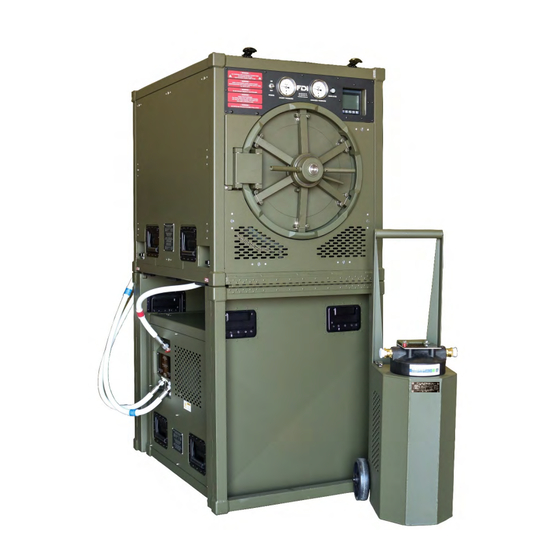
SECTION 3 – OPERATION The P2131 sterilizer system includes the following: 1. One SMU (P/N: P2131‐1) 2. One WRS (P/N: P2131‐2) 3. One SWS (P/N: P2131‐3) 4. One SAB (P/N: P2131‐4) Sterilizer Main Unit (SMU) Sterilizer Accessory Bag (SAB) Water Recovery Sterilizer Water System (WRS) Softener (SWS) ... - Page 16 Sterilizer Accessory Bag (SAB): The SAB is stored in the SMU chamber during transport but contains items necessary for both setup and maintenance. The items found in this bag include: 1. One Sterilizer Accessory Bag (P/N: P2131‐1‐7000) 2. Three SMU to WRS connection hoses Recovered Water Hose (P/N: P2131‐1‐3101) Vacuum/Exhaust Hose (P/N: P2131‐1‐3102) Condensate Hose (P/N: P2131‐1‐3103) 3. One high‐temperature drain hose (P/N: P2131‐1‐3104) 4. Six shelves (P/N: P2131‐1‐2002) 5. Twelve leveling shims (P/N: P2131‐1‐2016) 6. Handheld TDS (Total Dissolved Solids) Meter (P/N: P2131‐3‐9010) 7. Twenty‐five spare hose fitting O‐rings ...
-
Page 17: Installation, Setup, And Qualification (Iq, Oq, Pq)
INSTALLATION, SETUP, AND QUALIFICATION (IQ, OQ, PQ) WARNING: To prevent potential injuries during transport, installation and setup, FDI recommends a six‐person team lift for the SMU and a four‐person team lift for the WRS. 1. The P2131 sterilizer is designed to be carried by 6 people. 2. Place the SMU on one of its ends. ... - Page 18 3. Unlock the two latches holding the endcap against the main frame. 4. Holding securely onto the SIDES of the endcap, slowly pivot the endcap to the fully open position (do not allow endcap to drop). WARNING: A potential pinch point exists near the hinge area of the endcap. It is very important to keep hands positioned on the SIDES of the endcap and away from the pinch point. Placing your hand Proper hand near the hinge can result placement is on the side in injury. Keep hands of the end cap, away positioned on the sides from the pinch point. of the endcap and away This will help avoid injury from the pinch point. when opening the endcap. 5. On each side, screw the black endcap knobs down securely. Ensure the endcap knobs are fully seated by checking to see if the white washer in between the knob and the spring does not spin. Do not overtighten. ...
- Page 19 6. Tilt the SMU down onto the endcap that was just opened. 7. Position one person on each side of the SMU. Using the side‐carry handles, lift the unopened end of the unit, pivoting on the endcap that is already opened and secured. As the SMU is raised into position, rest the weight of the unit on your thigh, allowing you to unlock the two latches holding the endcap against the main frame. If a third person is available to help, they should be positioned at the end of the SMU to help unlock the latches. ...
- Page 20 WARNING: A potential pinch point exists near the hinge area of the endcap. It is very important to keep hands positioned on the SIDES of the endcap. 9. Once the endcap is lowered into position, screw the two black endcap knobs down securely. Ensure the endcap knobs are fully seated by checking to see if the white washer in between the knob and the spring does not spin. Do not overtighten. 10. Remove the SAB from the chamber of the SMU. The SAB contains items necessary to complete the assembly of the unit. Refer to Section 3.2.1 – Chamber Door Operation for instructions on operating the chamber door. The multi‐tool is stored in the rear endcap and will also be used (for S/N’s AFS‐0001 through AFS‐0215, the multi‐tool is in the SAB). Multi‐tool (P/N: P2131‐1‐2020) ...
- Page 21 11. Remove left side panel of SMU with the multi‐tool supplied in the rear endcap leg and perform visual inspection. On S/N’s AFS‐0001 through AFS‐0215, the multi‐tool is stored in the SAB. Ensure that: a. HEPA filter cartridge is not damaged. b. All wiring, hoses, and fittings are secure. c. Insulation is not damaged. d. There are no other visible issues or concerns. CAUTION: Hold panel firmly in place when loosening the panel latches. 12. Remove right side panel of SMU (side with inlet air filter to the electrical enclosure) and perform visual inspection to ensure that: a. There are no loose or disconnected wires. b. There are no damaged or loose components. c. The fuses are in place and not damaged. CAUTION: Hold panel firmly in place when loosening the panel latches. 13. Remove top panel and front/back panels of the WRS to ensure that: a. There are no loose or disconnected wires. b. There are no damaged or loose components. 14. Clean and wipe down the unit as needed and reinstall all panels. 15. Place the WRS next to the SMU, orienting the unit such that the side of the WRS with the power switch and sight glass are on the right side of the SMU when facing the front of the SMU. Then, slide the WRS under the SMU. ...
- Page 22 16. Remove the lower front panel of the SMU to access the connection for the condensate hose. Use the multi‐tool provided in the SAB to loosen the front panel latches, and then gently remove the panel. 17. On the bottom left side of the SMU is an access hole for the condensate hose (red‐tagged). Push the hose through this hole and unscrew the cap on the left side of the drain manifold. Ensure the O‐ring on the manifold fitting is in place, and then connect the hose to the condensate outlet on the chamber drain manifold. Hand‐tighten the nut and then tighten 45° (max) using the multi‐tool. NOTE: If the fitting O‐ring is missing, spare O‐rings are provided in the SAB. ...
- Page 23 18. Replace the lower front panel. 19. On the WRS, unscrew the “Condensate from Sterilizer (IN)” bulkhead cap, and verify that the O‐ring on the bulkhead fitting is in place. Attach the red‐tagged condensate hose. The connection has a red bulkhead retainer to match the red tag on the hose. Hand‐ tighten the nut and then tighten 45° (max) using the multi‐tool. NOTE: If the fitting O‐ring is missing, spare O‐rings are provided in the SAB. 20. On the back of the SMU, unscrew the “Vacuum/Exhaust to WRS (OUT)” bulkhead cap, and verify that the O‐ring on the bulkhead fitting is in place. Attach the white‐tagged vacuum/exhaust hose. The connection has a white bulkhead retainer to match the white tag on the hose. Hand‐tighten the nut and then tighten 45° (max) using the multi‐tool. NOTE: If the fitting O‐ring is missing, spare O‐rings are provided in the SAB. ...
- Page 24 21. On the WRS, unscrew the “Vacuum/Exhaust from Sterilizer (IN)” bulkhead cap, and verify that the bulkhead fitting O‐ring is in place. Attach the white‐tagged vacuum/exhaust hose. The connection has a white bulkhead retainer to match the white tag on the hose. Hand tighten the nut and then tighten 45° (max) using the multi‐tool. NOTE: If the fitting O‐ring is missing, spare O‐rings are provided in the SAB. 22. On the back of the SMU, unscrew the “Recovered Water from WRS (IN)” bulkhead cap, and verify that the bulkhead fitting O‐ring is in place. Attach the blue‐tagged recovered water hose. On the WRS, unscrew the “Recovered Water to Sterilizer (OUT)” bulkhead cap, and verify that the bulkhead fitting O‐ring is in place. Attach the blue‐tagged recovered water hose. These connections both have blue bulkhead retainers to match ...
- Page 25 23. The final hose configuration is pictured below. Red‐tagged Condensate Hose (P/N: P2131‐1‐3103) Blue‐tagged White‐tagged Recovered Water Hose Vacuum/Exhaust Hose (P/N: P2131‐1‐3101) (P/N: P2131‐1‐3102) 24. Unscrew the SMU power cord receptacle from its holder and set to the side. CAUTION: Do not connect this receptacle to a power source yet. SMU Electrical Power Cord Connecting Receptacle (P/N: P2131‐1‐4027) ...
- Page 26 25. Remove the WRS Power Cord Receptacle from its holder and connect the (P/N: P2131‐1‐0014) receptacle into the WRS Main Power Plug on the WRS. (P/N: P2131‐1‐4010) WRS Power Cord WRS Main Power Plug Receptacle (P/N: P2131‐2‐4010) (P/N: P2131‐1‐0014) 26. Ensure all three manual valves on the back of the SMU are closed firmly. Jacket Vent Chamber Vent Jacket Drain ...
- Page 27 27. For S/N’s AFS‐0001 through AFS‐0203, open the chamber door, and insert the chamber drain screen in the front of the chamber. The screen is in the large plastic bag found in the SAB. For S/N’s after AFS‐0203, verify the drain screen is already installed in the chamber. Do NOT operate the P2131 sterilizer without the chamber drain screen. NOTE: Remove the screen by rotating and pulling the screen upwards. The screen is not designed to be tightened. For S/N’s AFS‐0001 through AFS‐0203, the screen has an outward notch on the collar. For S/N’s after AFS‐0203, the drain screen has an O‐ring that locks the screen into the coupling in the bottom of the chamber. 28. For S/N’s after AFS‐0236, the following step can be skipped. For S/N’s AFS‐0001 through AFS‐0236, first remove Back Lower Panel and black Heater Assembly Cover. Reinstall the two Heater Flange Drain Caps at the rear of the unit by removing the caps from Tee Cap Retainers and tightening them to the Heater Flange Tees finger tight, then only one quarter‐turn with wrench. Reinstall Back Lower Panel and Heater Assembly Cover. Tee Cap Retainers (S/N’s AFS‐0001 – 0236) Heater Flange Tees ...
- Page 28 30. Using the shims provided in the side zipper section of the SAB, elevate the rear of the SMU to ensure there is a slight decline from the back of the unit toward the front to allow the condensate in the chamber to drain properly. From a level starting point, this will be approximately 4 shims or 1” under the rear endcap. The target angle is 1.5°. 31. To test for proper angle, pour a cup of water in the back of the chamber, and ensure that it flows to the chamber drain. 32. Clean the chamber, and then install the trays found in the SAB. CAUTION: Do not allow sand, chemicals, or other debris to flow down the chamber drain into the WRS. This could contaminate the water or damage components in the WRS. 33. Ensure that the power switches for the SMU and WRS are in the OFF position. ...
- Page 29 See Section 2.5 – Water Supply Quality to ensure the correct quality of feedwater is used. CAUTION: Water in SWS can foul and become discolored if not used regularly. Outlet Hose (To WRS) Water Supply Hose (P/N: P2131‐3‐3006) 36. For S/N’s AFS‐0001 through AFS‐0236, with the yellow valve handle as shown below, connect the clear Outlet Hose from the SWS to the Fill Connection on the bottom of the WRS. This is a cam‐style connection. Ensure WRS drain valve is closed, then open the yellow valve on the end of the SWS outlet hose (pictured below) to allow water to flow into the tank. Once the HIGH mark is reached, close the yellow valve at the end of the SWS outlet. ...
- Page 30 NOTE: If a pressurized water source is not available, the manual hand pump mounted on the SWS can be used to pump potable water from a bucket or Jerry can. Before each use, flush SWS until water is clear (2 minutes). Release the two Handle Latches and fold the handle down to expose the manual hand pump and hoses. Connect the Suction Line and drop strainer into a Jerry can or bucket. Handle Latches Suction Strainer Manual Hand Pump (P/N: P2131‐3‐3009) (P/N: P2131‐3‐0003) Suction Line to Manual Hand Pump (P/N: P2131‐3‐3007) Hook hand pump Discharge Line to Inlet of SWS. Discharge Line to Inlet of SWS (P/N: P2131‐3‐3008) Push/pull the white handle back and forth to pump water into the WRS. Once the HIGH mark is reached, close the yellow valve at the end of the SWS outlet hose and the blue valve on the Water Fill Connection. ...
- Page 31 37. Flip the power switch on the WRS to the ON position (UP position). 38. Close and tighten the chamber door. Flip the control power switch on the SMU to the ON position (UP position). NOTE: When the SMU is turned ON with no water in the jacket, a “Low Water” alarm will occur and the WRS will turn ON. This alarm confirms that the liquid level switch is functioning correctly in the “Low Water” position. The alarm will prevent the heater elements from energizing, but will allow operation of the WRS to fill the jacket with water. (The “Low Water” alarm will be reset in a later step). WARNING: If this “Low Water” alarm does not occur, turn the sterilizer OFF immediately to prevent damage to the heater elements. Contact a qualified ...
- Page 32 39. Ensure the jacket vent valve on the back of the SMU is fully open and close the chamber vent valve. This will allow the jacket to vent the air while it is filled with water from the WRS. Minimizing air in the jacket improves sterilizer performance since air acts as an insulator during sterilization. 40. Press and hold the “Water to Sterilizer” button on the WRS and fill the SMU to the HIGH mark on the level sight glass. This should pump about 4.25 gallons of water into the jacket of the sterilizer. Add water to the WRS with the SWS as needed to fill the SMU to the HIGH mark. CAUTION: Verify the SMU sight glass fills from the bottom. If not, contact a qualified maintenance technician to inspect the sight glass plumbing for debris. CAUTION: Never add water to the jacket during a cycle. This will cause the jacket to cool, lose pressure, and alarm. 41. Firmly close the jacket vent valve on the back of the SMU. 42. Refill the WRS back to its HIGH mark and disconnect the SWS hose. NOTE: The correct water levels are HIGH/HIGH ‐ when the water is at the HIGH mark in the jacket, the water level should be at or near the HIGH mark in the WRS. 43. Reset the “02 – LOW WATER LEVEL” alarm. If the alarm clears, the liquid level switch is functioning correctly in the “Water OK” position. ...
- Page 33 “Log” screen after each cycle for recording results. This can be especially helpful if there is more than one sterilizer in operation. The factory default for this UNIT ID is 2131. This can be changed as desired by the user. 45. Barometric Pressure Setup. Since the P2131 sterilizer is designed for altitudes ranging from sea level to 8,000 feet, the “BAROMETRIC SETUP” screen is used to set the gauge pressure in the PLC to zero. NOTE: The sterilizer control system uses absolute pressure transmitters for cycle ...
- Page 34 This test will ensure that the air removal process during the pre‐vac phase is working correctly. (Reference Section 3.3.4 for procedure.) 51. Perform Performance Qualification using PCDs per AAMI ST79 standards. Reference Section 2.6 for information on recommended sterility assurance products. 52. After all of these tests are successful, the P2131 sterilizer is ready for OPERATION. If any of these tests fail, the sterilizer cannot be placed into service. Call a qualified maintenance technician for repair. It is critical to reference Section 3.2 to become familiar with all Controls & Indicators before following the Operating Procedure in Section 3.3. ...
-
Page 35: Controls And Indicators
Controls and Indicators Sterilizer Main Unit (SMU) 2. Control Power 4. Indicator Light (LAMP‐1) 3. Pressure Gauges Switch (SW‐1) (P/N: P2131‐1‐4018) (P/N: P2131‐1‐3406) (P/N: P2131‐1‐4017) 5. Controller (P/N: P2131‐1‐4000) 1. Warnings 6. Audible Alarm (ALM‐1) (behind panel) (P/N: P2131‐1‐4008) 7. Door Handles (P/N: P2131‐1‐1020) 8. Locking Arm Lever (P/N: P2131‐1‐1023) 9. Radial Arms (P/N: P2131‐1‐1021) Front View of SMU ... -
Page 36: Chamber Door Operation
Function(s) of Control or Indicator (Front View of SMU) ITEM CONTROL/INDICATOR FUNCTION Critical warnings for the safe operation and maintenance of the 1. Warnings P2131. Be sure to reference all warnings listed in Section 1.1. A two‐position toggle switch that energizes the control system and 2. Control Power Switch heater elements. Up position is ON, and down is OFF. 3. Pressure Gauges Indicates gauge pressure (psig) in jacket and chamber. Green = Successful cycle = Jacket warming up 4. Indicator Light Red = Alarm No light = Idling or in a cycle. Touch‐screen controller for operating the P2131 sterilizer. For 5. Controller details on the menu, screens, and all functions, reference Section 3.3 ‐ Operating Procedure. Buzzer/alarm to audibly notify the operator of conditions. Single tone = successful cycle 6. Audible Alarm Three tones in rapid sequence = alarm notification Sustained Tone = Low water & Liquid Level Switch malfunction or damaged HTS‐1 RTD Turning these handles tightens and seals the door into place. 7. Door Handles These handles may become warm during operation. Pivots the radial arms to lock the door into place as well as 8. ... - Page 37 12b. Tee Cap Retainer 1. Water Level Sight Gauge 6. Vacuum/Exhaust (P/N: P2131‐1‐3405) Hose Connection (White‐Tagged) (P/N: P2131‐1‐9007) 9. Jacket Drain Valve (P/N: P2131‐1‐0039) 5. Recovered Water Hose Connection (Blue‐Tagged) 12a. Tee Cap Retainer (P/N: P2131‐1‐9007) 10b. Heater Flange Drain 7. Jacket and Chamber Cap, Water Level Manual Vent Valve Outlets (P/N: P2131‐1‐3016) (P/N: P2131‐1‐9008) 8. Jacket Drain Hose 10a. Heater Flange Connection Drain Cap, Fill (P/N: P2131‐1‐9009) (P/N: P2131‐1‐3015) *Note: Back Lower Panel (P/N: P2131‐1‐0139) and Heater Assembly Cover (P/N: P2131‐1‐9041) are required but not shown. They are depicted on the 11. Multi‐tool next page. (P/N: P2131‐1‐2020) ...
- Page 38 Rear View of SMU for S/N’S after AFS‐0236 4. Chamber Vent Valve (P/N: P2131‐1‐0034) 2. Pressure Safety Valve (P/N: P2131‐1‐3403) 3. Jacket Vent Valve (P/N: P2131‐1‐0035) 1. Water Level Sight Gauge 6. Vacuum/Exhaust (P/N: P2131‐1‐3405) Hose Connection (White‐Tagged) (P/N: P2131‐1‐9007) 13. Back Lower Panel (P/N: P2131‐1‐0139) 5. Recovered Water Hose Connection (Blue‐Tagged) (P/N: P2131‐1‐9007) 14. Heater Assembly Cover 7. Jacket and Chamber (P/N: P2131‐1‐9041) Manual Vent Valve Outlets (P/N: P2131‐1‐9008) 9. Jacket Drain Valve (P/N: P2131‐1‐0039) 8. Jacket Drain Hose Connection (P/N: P2131‐1‐9009) 11. Multi‐tool (P/N: P2131‐1‐2020) ...
- Page 39 Function(s) of Control or Indicator (Rear View of SMU) ITEM CONTROL/INDICATOR FUNCTION Indicates water level inside jacket. Fill to HIGH mark. A low water level 1. Water Level Sight Gauge switch (separate from sight gauge and not shown in picture) will create an alarm, abort the cycle, and de‐energize the heaters. Pressure Safety Valve Relieves overpressure @ 40 psig to prevent potential rupture of 2. (PSV) jacket/chamber Manual valve that opens the jacket to atmosphere. This valve must be closed during normal operation. Best practice includes NOT opening 3. Jacket Vent Valve this valve after shutdown to vent steam, but allow SMU to cool and steam to condense (this will pull a vacuum in jacket, which is OK). Manual valve that opens the chamber to atmosphere. This valve must be closed during normal operation. This valve is used to relieve 4. Chamber Vent Valve pressure or vacuum (e.g., if vacuum develops in chamber from accidently leaving door closed during cool down). Recovered Water Hose 5. Connection (Blue‐ This hose supplies water to the jacket from the WRS. Tagged) Vacuum/Exhaust Hose This hose exhausts steam/air and allows the WRS to create the vacuum 6. Connection (White‐ necessary for sterilizer operation. Tagged) Outlet points for the Jacket and Chamber vent valves. Jacket and Chamber WARNING: A small amount of hot condensate will collect above these ...
- Page 40 1. Inlet Air Filter (behind panel) (P/N: P2131‐1‐5001) 2. Endcap Knob (P/N: P2131‐1‐0020) Right Side of SMU 3. Carry Handle (P/N: P2131‐1‐5011) Function(s) of Control or Indicator (Right Side of SMU) ITEM CONTROL/INDICATOR FUNCTION Filters air for cooling electrical components. Filter is Inlet Air Filter 1. washable and should be inspected and cleaned. (behind panel) Reference Section 4, Post‐Maintenance Checklist. Located on each corner of the SMU, these are used to secure endcap in down position during setup. When breaking down the sterilizer for storage or transport, 2. Endcap Knob the endcap knobs should be turned counter‐clockwise. When the knobs disengage from the endcap, a spring will pop them upwards, indicating they are free. Recessed spring‐loaded handle used for transporting 3. ...
- Page 41 Water Recovery System (WRS) The WRS reclaims steam and condensate from the SMU for re‐use. A circulation pump and heat exchanger allow for hot steam to be cooled and condensed into water. A water eductor creates a vacuum during the preconditioning phases to remove air and provides a deep vacuum to assist in drying a load during the dry phase. The WRS also provides an easy, push‐button method to refill the SMU jacket. NOTE: The Power Switch on the WRS should always be in the ON position during operation. 3. Water Return Switch (SW‐2) (P/N: P2131‐2‐4009) 2. HIGH Water Line 4. Power Switch (SW‐3) (P/N: P2131‐2‐4008) 5. Power Connection 1. LOW Water Line (P/N: P2131‐2‐4010) ...
- Page 42 Function(s) of Control or Indicator (Right Side of WRS) ITEM CONTROL/INDICATOR FUNCTION Water level in the tank is indicated by the position of a floating ball inside the Sight Gauge tubing. On S/N’s after AFS‐0236, a water line in the Sight Gauge tubing indicates the water level. During operation, the water level should be at or near the HIGH water line (when the jacket is at 1. LOW Water Line the HIGH mark). If the water level becomes too low, the Low Level Switch (located underneath the tank near the motor) will activate and prevent the pump from running dry. If the pump starts and stops, or will not operate, water likely needs to be added to the WRS. Water level in the tank is indicated by the position of a floating ball inside the Level Gauge tubing. On S/N’s after AFS‐0236, a water line in the Sight Gauge tubing indicates the water level. During operation, the water level should 2. HIGH Water Line be maintained at or near the HIGH water line. Overfilling and running the WRS with water above the HIGH mark (when the jacket is at the HIGH mark) may result in water “burping” out of the relief vent or breather on top of the WRS water tank. A push‐button that turns ON the pump to flow water into Water Return Switch 3. the sterilizer when pressed. Releasing the switch will stop (SW‐2) the flow of water. A two‐position switch that turns electricity ON and OFF to 4. Power Switch (SW‐3) the WRS. This switch also has a 20‐amp circuit breaker built into the switch. Where the power cord from the SMU is plugged into the 5. ...
- Page 43 3. Condensate Hose Connection (Red‐Tagged) (P/N: P2131‐2‐0009) 2. Vacuum/Exhaust Hose Connection (White‐Tagged) (P/N: P2131‐2‐0009) HOT CAUTION Label (S/N’s after AFS‐0236) 1. Recovered Water Hose Connection (Blue‐Tagged) (P/N: P2131‐2‐0009) Left Side of WRS Function(s) of Control or Indicator (Left Side of WRS) ITEM CONTROL/INDICATOR FUNCTION Recovered Water This hose carries water from the WRS into the jacket in 1. Hose Connection the SMU when the water return switch is depressed. (Blue‐Tagged) This hose exhausts steam/air from the SMU chamber Vacuum/Exhaust and connects to a water eductor inside the WRS, which 2. Hose Connection generates the vacuum needed for the pre‐vac and post‐...
- Page 44 Sterilizer Water Softener (SWS) The SWS is critical to the long‐term reliability and performance of the P2131 sterilizer. The purpose of the SWS is to remove ions (e.g., calcium, magnesium, and chlorides) from the water to prevent scale buildup on the heating elements, jacket walls, and other components. 3. Outlet Hose 1. Inlet Hose Connection Connection (P/N: P2131‐3‐3004) (P/N: P2131‐3‐3005) 2. Pentek Big Blue, 20”x3/4”, Housing (P/N: P2131‐3‐9013) 4. Outlet Hose (to WRS) (P/N: P2131‐3‐3006) ...
- Page 45 Panel Fasteners 5. Spanner Wrench (P/N: P2131‐3‐1012) 3. Discharge Line to Inlet of SWS (P/N: P2131‐3‐3008) 2. Manual Hand Pump (P/N: P2131‐3‐0003) 4. Suction Strainer (P/N: P2131‐3‐3009) 1. Suction Line to Manual Hand Pump (P/N: P2131‐3‐3007) Rear View of SWS Function(s) of Control or Indicator (Rear View of SWS) ITEM CONTROL/INDICATOR FUNCTION Used when manual hand pump is in service. Water flows Suction Line to 1. from bucket or Jerry can through hand pump and into Manual Hand Pump SWS. ...
-
Page 46: Operating Procedure
Operating Procedure Overview of Touch‐Screen Operator Control Panel The P2131 sterilizer is controlled with an advanced programmable logic controller (PLC) with a touch‐screen display that performs pre‐programmed sterilization cycles and performance tests. NOTE: The following instructions assume that the P2131 sterilizer has been set up, checked out, and potable water is already in the SMU and WRS. Reference Section 3.1. NOTE: The “System” and “F1” through “F3” buttons are disabled. The “F4” button is only used as part of maintenance of the PLC. 3.3.1 TURNING THE STERILIZER ON: 1. Flip up the Control Power Switch on the front panel to turn the sterilizer ON. ... -
Page 47: Zeroing Gauge Pressure (Barometric Pressure Setup)
3.3.2 ZEROING GAUGE PRESSURE (BAROMETRIC PRESSURE SETUP): Since the P2131 sterilizer is designed for altitudes ranging from sea level to 8,000 feet, the “BAROMETRIC SETUP” screen is used to set the gauge pressure in the PLC to zero. NOTE: The sterilizer control system uses absolute pressure transmitters for cycle operation. By pressing ZERO, the controller knows the exact atmospheric pressure so that the chamber can be vented consistently to 0 psig (equal to atmospheric pressure). This allows the chamber door to be opened easily, and not be locked with a vacuum. 1. From the “CONFIRM SETUP” screen, press the “BAROMETRIC PRESSURE SETUP” ... - Page 48 2. Open the door. Insert items to be sterilized. Close and tighten the door. On the “Main Menu” screen, choose “STERILIZER CYCLES”. 3. On the “STERILIZER CYCLES” screen, choose the type of sterilization cycle that you need to run. 4. For the TEXTILES or WRAPPED INSTRUMENTS cycles, use the arrow buttons to select the desired dry time. For the WRAPPED INSTRUMENTS cycle, select the 4‐minute or 10‐minute exposure. Press the “ACCEPT” button. CAUTION: ...
- Page 49 5. Verify that the jacket water level is sufficient, the chamber vent valve is closed, and the chamber door is closed and tightened. Then press “START” to initiate the cycle. NOTE: When water is added to the jacket, there will be a slight cooldown, and therefore a reduction in pressure. The pressure in the jacket will need a few minutes to recover when water is added. If the jacket is not at setpoint pressure (see NOTE above), the “START” screen will display “WARMING UP” instead of “Ready”. If you choose “START” before the jacket is ready, the “START” button will disappear and the display will show “Cycle Pending.” Once the jacket is up to setpoint pressure, the cycle will begin automatically. During the cycle, the run screen will display the total cycle time, type of cycle, phase within the cycle, the time remaining (for exposure, drying, or vacuum testing only), the chamber temperature, and the chamber pressure. A cycle can be aborted at any time by choosing the “ABORT” button. This will stop the cycle and vent the chamber. Total Cycle Time Cycle Type Phase within Cycle Time Remaining ...
-
Page 50: Running A Performance Test (Vacuum Leak Or Bowie-Dick Test)
The “Log” screen will be displayed at the end of the cycle showing the results of the cycle. A total of 40 previous “Log” entries can be viewed using the LEFT and RIGHT arrows. The “Log” screen can also be accessed from the “Main Menu.” 3.3.4 RUNNING A PERFORMANCE TEST: 1. On the “Main Menu” screen, choose “TESTS”. 2. On the “Performance Tests” screen, choose either “BOWIE‐DICK TEST” or “VACUUM LEAK TEST.” For a BOWIE‐DICK TEST: Place a U.S. Food and Drug Administration (FDA)‐approved BOWIE‐DICK test pack on the bottom rack near the drain in the chamber. Follow all test pack manufacturer’s recommended procedures. For example, a warmup cycle (e.g., IUSS 4/0) should always be run prior to the BOWIE‐DICK test. ... - Page 51 For a VACUUM LEAK TEST: The sterilizer should be warmed up prior to running the VACUUM LEAK TEST by running any cycle (e.g., Textile 4/5) before the test. The VACUUM LEAK TEST consists of two phases. The first phase is a settling phase (5 minutes) and the second phase is the test phase (15 minutes). The P2131 sterilizer will conduct both phases automatically, and a countdown timer will indicate the time remaining for each phase. At the end of a successful test, the “Log” screen will appear. An “ALARM” screen will appear if unsuccessful. WARNING: A VACUUM LEAK TEST should be performed when the sterilizer is set up at a new location or after any major service or maintenance. In a hot environment the test may take longer because the WRS water may be hot, which affects the eductor’s ability to pull a deep vacuum. Perform the test when the WRS water ...
-
Page 52: Alarms
During the cycle, the “RUNNING” screen will display the total cycle time, type of test, where it is in the cycle, the time remaining (during exposure or vacuum testing only), the chamber temperature, and the chamber pressure. A test can be aborted at any time by choosing the “ABORT” button. This will stop the test and vent the chamber. 7. At the end of the test, the buzzer will sound and the chamber will vent. Once the chamber is completely vented, the door can be opened. NOTE: Unlocking the door (which actuates the door switch) before the chamber reaches 0 psig will stop the venting and may create a situation in which the door may not open due to vacuum in the chamber. If this happens, lock the door and press “VENT” from the “Log” screen. ... -
Page 53: Maintenance Reminder
Choosing to “RESET” will either (1) switch the display to the “Log” screen or (2) repeat the same alarm if the condition is still present. The controller will not allow the sterilizer to continue until the alarm has been reset. For example, if the alarm was “02‐Low Water Level,” water will need to be added to the jacket before the alarm will reset. The controller will then display the “Log” screen with the details of the alarm for recordkeeping. 3.3.6 MAINTENANCE REMINDER: Per FDA regulations, every 100 cycles or 14 calendar days, the water in the entire system must be drained and refilled. After every 100 cycles, a “Maintenance Reminder” screen is shown to remind the operator that the water in the SMU jacket, the WRS, and the SWS must be drained and replenished with fresh potable water. If needed, flush the SWS until clear (2‐minute flush). This reminder also serves to help encourage maintenance technicians to check and follow the recommended maintenance schedule (Reference Section 4). 3.3.7 STATUS: The “STATUS” screen can be accessed (except when a cycle is running) in order to look at data such as jacket pressure, chamber pressure, chamber condensate temperature (both RTDs), whether the door switch is showing open or closed, if the water level is OK or low, and how many total cycles the unit has run. ... -
Page 54: Programmable Cycles
3.3.8 PROGRAMMABLE CYCLES: WARNING: Only the standard AAMI cycles listed in Section 2.3 have been cleared by the FDA. Programmable cycles have not been validated. The FDA highly recommends that programmable cycles be used for research purposes. The user accepts all risks associated with sterilizing any load using a programmable cycle. Programmable cycles allow the user to run cycles with exposure times that can range from 15 minutes to 40 minutes in increments of 5 minutes. Dry times can range from 0 to ... - Page 55 4. After checking the water level, ensuring the chamber vent valve is closed, and tightening the door, press “START” to begin the cycle. 5. At the end of the cycle, the buzzer will sound and the chamber will vent. Once the chamber is completely vented, the door can be opened. NOTE: Unlocking the door (which actuates the door switch) before the chamber reaches 0 psig will stop the venting and may create a situation in which the door may not open due to vacuum in the chamber. If this happens, lock the door and press “VENT” from the “Log” screen. ...
-
Page 56: Operational Checklists
3. Test the TDS (Total Dissolved Solids) of the water and replace the deionized water cartridge as needed. (Reference Section 3.4.1 Testing Total Dissolved Solids and Section 4.3.4 SWS Cartridge Replacement) 4. Follow every step of Section 3.7 ‐ Checklist for Transport and/or Storage to prevent storage‐related issues upon startup. Why the SWS is Important: Preventing scale buildup (buildup of mineral deposits) is critical for ensuring that the P2131 sterilizer continues to operate reliably for many years. Preventing scale buildup will keep heat‐up times short. In addition, scale buildup can cause small pieces of scale to plug valve orifices and fittings. Lastly, if deionized water from the SWS is used, the sterilizer jacket and heating elements will not require costly labor and downtime for cleaning. ALWAYS ensure that the SWS is used for every fill‐up to the WRS to keep minerals out of the entire system. ... - Page 57 ROUTINE STARTUP CHECKLIST CHECK OPERATION 1. Remove and clean the chamber drain screen. (Inspect O‐ring for potential damage on S/N’s after AFS‐0203. Replace with spare from SAB if necessary). 2. Ensure chamber and jacket vent valves are closed. 3. Flip the control power switch to the “ON” position. 4. Fill the jacket with water to the HIGH mark using the WRS. NOTE: Never add water to the sterilizer during a cycle. This will cause the jacket to cool off, lose pressure, and alarm. 5. Ensure the water level in the WRS is at, or near, the HIGH mark. If not, add water using the SWS. 6. Run an IUSS cycle to warm up the chamber. NOTE: It is critical to run this warmup cycle to ensure successful completion of the Bowie‐Dick test. 7. Run a Bowie‐Dick test per AAMI standards to ensure that air removal during the preconditioning phase is functioning properly. 8. Proceed with a normal sterilization cycle as needed. WARNING: Run a VACUUM LEAK TEST on a periodic basis per AAMI standards or at least weekly and always after any transport, relocation, or ...
- Page 58 ROUTINE SHUTDOWN CHECKLIST CHECK OPERATION 1. Add water to the jacket to the HIGH mark. This will help (1) cool down the jacket and (2) ensure that the jacket is full of water and ready to run again when needed. Also, “top off” the WRS water level to the HIGH mark using the SWS if needed. 2. Leave the chamber door latched but not tightened to prevent a vacuum from being created in the chamber during cooldown. To break a vacuum in the chamber and open the door, press the “VENT” button on the control panel touch screen. 3. Turn OFF SMU control power switch. DO NOT open the jacket vent valve. NOTE: As the SMU cools down, the steam in the jacket will condense, resulting in a deep vacuum. This condition is not a problem and will not cause any damage to the SMU. In fact, this is a recommended practice since relieving the vacuum by opening the jacket vent valve will allow air to enter the jacket. Keeping air out of the jacket will enable the next cycle to operate more efficiently. Air is the enemy of effective sterilization. WARNING: If freezing temperatures are possible around the sterilizer, all water from the SMU, WRS, and SWS must be drained to prevent possible freezing and damage to the pressure vessel, pump, SWS housing, or other components. Reference Section 3.7 for information on draining water. ...
- Page 59 DAILY OPERATOR CHECKLIST CHECK TASK 1. Remove and clean the chamber drain screen (Inspect O‐ring for potential damage on S/N’s after AFS‐0203. Replace with spare from SAB if necessary). 2. Wipe the chamber interior surfaces and shelves. WARNING: Do not allow any contaminants to go down the chamber drain and into the WRS. 3. Look and listen for possible water and steam leaks. 4. Verify that the cooling fans in the SMU (qty: 1) and the WRS (qty: 2*) are running. NOTE: On S/N’s after AFS‐0236, there is only 1 cooling fan mounted to the Back Panel of the WRS. 5. Monitor water levels in the SMU jacket and WRS. NOTE: When the SMU jacket is at the HIGH mark, the WRS water level should be at or near the HIGH mark also. REMEMBER: Always use the SWS when adding water. 6. Listen for any abnormal sounds during operation. Notify a qualified maintenance technician if there is a concern. ...
- Page 60 FDA‐REQUIRED WATER CHANGEOUT EVERY 14 DAYS OR 100 CYCLES (WHICHEVER OCCURS FIRST) CHECK TASK 1. Clean the SMU chamber thoroughly using a mild detergent: a. Disconnect the condensate hose (red‐tagged) at the WRS and place the end into a bucket. b. Drain any cleaning water / mild detergent into the bucket. c. Flush the hose with fresh water and then reconnect the hose to the WRS. WARNING: Do not allow any water or detergent to drain into the WRS. 2. Drain all the water from the SMU jacket by following the Jacket Blowdown Procedure in Section 4.1.2. WARNING: To avoid a potential burn hazard, ensure the high‐ temperature drain hose is used. 3. Drain the WRS by attaching the drain hose and opening the drain valve. 4. SWS maintenance: a. Test the TDS level of the water coming out of SWS and replace the deionized water cartridge as needed. Reference Section 3.4.1 Testing Total Dissolved Solids and ...
-
Page 61: Testing Total Dissolved Solids (Tds)
(e.g., every 14 days or 100 cycles, whichever occurs first). Follow the instructions below. Cartridge Replacement Criteria: If SWS outlet water TDS is ≥ 15 ppm, replace the SWS DI Water Cartridge. If the TDS reading is < 15 ppm, the SWS can be used as normal. NOTE: If the feedwater is of poor quality and has a high TDS level, a brand‐new cartridge may result in a TDS reading of greater than 15 ppm. To improve the TDS reading: 1. Improve incoming water quality. 2. Use SWS’s in series to lower the TDS level before filling WRS. 3. Using a collection bucket or Jerry can, reprocess the water twice through the SWS before filling the WRS NOTE: The meter is not water‐tight. Do not dip the meter beyond the water level limit. Handheld TDS Meter P/N: P2131‐3‐9010 TDS Handheld Meter Calibration Check (every 6 months): Immerse the meter into distilled water and verify it reads ≤ 5 ppm. If it reads > 5 ppm, either the distilled water could be contaminated, or TDS Meter is out of calibration and should be replaced. Taking a TDS Measurement: 1. Remove the protective cap. 2. Turn the TDS Meter ON. 3. Collect a sample of SWS outlet water in a clean container. 4. Immerse the Meter into the sample up to the Water Level Limit. 5. Lightly stir the Meter in the water to dislodge any air bubbles. 6. Wait until the reading stabilizes and then press the HOLD button. The value displayed is the TDS Level of the water. ... -
Page 62: Testing Free Chlorine Level
If no free chlorine is present, water can foul. Free chlorine, in water, will completely evaporate within 24 hours and the evaporation rate increases when the water is exposed to the atmosphere. Trace amounts of free chlorine will be filtered out through the SWS Deionizing (DI) cartridge. Using the free chlorine test strips provided in the SAB, test the supply water and SWS outlet water stream every time the SMU jacket and WRS are drained and refilled (e.g., every 14 days or 100 cycles, whichever occurs first). Follow the instructions listed on the chlorine test strip container to test the Free Chlorine Level. Chlorine Test Strip P/N: P2131‐3‐9007 Test the supply water and outlet water stream as shown below: 3. Connect the Outlet Hose 1. Locate and test the Connection to supply water with the SWS the test strip ... -
Page 63: Operational Situations And Responses
Section 3.5 Operational Situations and Responses SMU – Testing Related Situations What do you do if … Response A biological indicator fails but Reprocess per latest edition of ANSI/AAMI ST79. the cycle ran successfully with no alarms? The Bowie‐Dick Test fails? Reprocess per latest edition of ANSI/AAMI ST79. Was a warm‐up cycle (IUSS) run to ensure that the chamber was heated up? If NO, then run the Bowie‐Dick test again. If YES, then call a qualified maintenance technician to troubleshoot. The Vacuum Leak Test fails? Take the sterilizer out of service and contact a qualified maintenance technician who will use the Vacuum Leak Test troubleshooting guide in Section 4.3.14. SMU – Cycle and PLC Related Situations What do you do if … Response The unit shuts off and emits a Turn the SMU OFF and disconnect power. Contact a qualified sustained alarm tone? maintenance technician to troubleshoot the system. You experience a power Flip the control power switch to the OFF position. When the failure during operation? power returns, flip the control power switch ON. If the power outage was short, there will still be pressure in the jacket and pressure or vacuum in the chamber. Press “CONFIRM” on the “SETUP” screen, then press “VENT.” This will vent the pressure or vacuum in the chamber. After venting, open the door and reprocess the load per AAMI ST79 standards. You want to stop a cycle? Press “ABORT.” ... - Page 64 SMU – Water and Steam Related Situations What do you do if … Response You hear or see a steam leak If it is safe to do so, turn the control power switch OFF and somewhere other than the allow the sterilizer to cool and depressurize. Contact a door? qualified maintenance technician. You hear or see a steam leak If it is safe to do so, wait for the cycle to finish and then inspect at the door? the door frame and door gasket for any debris that could prevent a good seal. Closely inspect the gasket for any damage such as nicks or cuts. Replace it if needed. If there is no damage, then tighten the door a little tighter on the next cycle. You get a low water alarm? Add water to the SMU from the WRS, close and tighten the chamber door, press “RESET,” and restart the cycle. Also, recheck level in WRS after pumping and refill using the SWS if needed. It is best to run the WRS at the HIGH water mark (when the jacket is at the HIGH mark). The jacket is overfilled with Turn the sterilizer OFF and let it cool down and depressurize. water? With zero pressure on the jacket, attach the high‐temperature hose and drain enough water out of the jacket to bring the level down to the HIGH mark on the sight gauge. Close the drain valve and turn the sterilizer back ON. The jacket fills with water, but Contact a qualified maintenance technician for further VERY slowly? diagnosis and repair on the WRS pump. The jacket does not refill Verify the water level in the WRS, adding water through the when switch on WRS SWS if necessary. Ensure that the power cord is plugged into depressed? the WRS and that the power switch is in the ON position. If the problem continues, contact a qualified maintenance technician for further diagnosis and repair. ...
- Page 65 What do you do if … Response Water is seen entering the Contact a qualified maintenance technician to inspect and clean SMU sight glass through the the Liquid Level Switch and Sight Glass plumbing. Address any top during jacket fill‐up blockages or issues found. SMU – General Situations What do you do if … Response There is a vacuum in the No response needed. This is normal. The sterilizer can be jacket at startup? turned on as usual. There is algae in the sterilizer No response needed. Algae forms due to heat and light. It is sight glass? normal and will not affect sterilization. To clean the sight glass, follow the procedure found in Section 4.3.3. The chamber door will not Press “VENT” on the “Main Menu” or the “Log” screen. If you open due to vacuum on the still cannot open the door, open the chamber vent valve in the chamber? back of the SMU to vent the chamber. You hear an abnormal sound? Take the sterilizer out of service and contact a qualified maintenance technician. During exposure, the two One of the gauges is likely malfunctioning. Contact a qualified pressure gauges are maintenance technician. different? The chamber is failing to pull Contact a qualified maintenance technician. vacuum during pre‐vac or drying? WRS and SWS – General Situations ...
-
Page 66: Alarm Code Troubleshooting Guide
Alarm Code Troubleshooting Guide WARNING: Service and maintenance work must be performed by qualified personnel only. ALARM POSSIBLE CAUSES CORRECTIVE ACTION CODE Liquid Level Switch Turn the SMU OFF and disconnect power. Inspect Liquid Malfunction & Unit Level Switch. Does float move freely? Electrical continuity run with low or no of Liquid Level Switch with water? No continuity without water water? Replace liquid level switch or fix root cause of the malfunction. Re‐qualify the switch per Operational Qualification (OQ) of the Liquid Level Switch before placing the unit back into service. See Section 3.1. Sustained Alarm Tone If Liquid Level Switch is functional, inspect plumbing that Plug / debris in & leads to switch, including the heater flange tees, the hoses Liquid Level Switch PLC Off and any other fittings. Remove blockage and flush hoses. Plumbing & Unit Re‐qualify the switch per Operational Qualification (OQ) of run with low or no the Liquid Level Switch before placing the unit back into ... - Page 67 ALARM POSSIBLE CAUSES CORRECTIVE ACTION CODE Jacket manual vent Close jacket vent valve. valve open 03 Warm up ambient conditions to 40°F, if possible. Low ambient temperatures Jacket Warmup Heater element Contact a qualified maintenance technician to inspect and Slow failure replace heater element. Contact a qualified maintenance technician to inspect Scale buildup on heaters and jacket walls and clean as needed. Ensure SWS heater elements is being used on every water refill. and jacket Steam leak Inspect door gasket and chamber fittings for steam leaks. Faulty steam trap Ensure trap is working properly. If steam trap is failed closed, condensate will pool in chamber. If steam trap fails ...
- Page 68 ALARM POSSIBLE CAUSES CORRECTIVE ACTION CODE Steam leak Inspect door gasket and chamber fittings for steam leaks. Faulty steam trap Ensure trap is working properly. If steam trap is failed closed, condensate will pool in chamber. If steam trap fails open, steam will flow to WRS water tank and make a loud popping noise or use more water than normal. Replace as needed. RTD or RTD Contact a qualified maintenance technician to inspect RTD transmitter failure and RTD transmitter for physical damage, loose wires, broken communication cable to PLC. 05 Compare temperature versus pressure on STATUS screen. Long Replace as needed. Exposure Time Condensate drain Remove and clean screen. screen plugged ...
- Page 69 ALARM POSSIBLE CAUSES CORRECTIVE ACTION CODE Loose Inspect O‐rings at each end and re‐tighten the hose. vacuum/exhaust hose fittings (white‐ tagged hose) Pump not operating Check WRS water level, power cord, and power switch. in WRS Hot water in WRS Ensure both WRS fans are running when pump is ON. Ensure water level is at least 1/2 full. Too little water will 06 tend to overheat and cause low eductor performance. Insufficient Vacuum Eductor problem in Contact a qualified maintenance technician to inspect WRS eductor for leak or worn/broken nozzle inside eductor. Replace if needed. Vacuum valve not Contact a qualified maintenance technician to inspect ...
- Page 70 ALARM POSSIBLE CAUSES CORRECTIVE ACTION CODE Gasket leak at door Inspect for leak with pressure and identify location. Inspect gasket for debris or cut. Replace as needed. Manual chamber Contact a qualified maintenance technician to inspect vent vent valve leaking valve and replace as needed. Faulty steam trap Ensure trap is working properly. If steam trap is failed closed, condensate will pool in chamber. If steam trap fails open, steam will flow to WRS water tank and make loud popping noise or use more water than normal. 08 Replace as needed. Chamber Pressure Vacuum/Exhaust Contact a qualified maintenance technician to inspect Low valve leaking outlet of valve for leaking. Sterilize valve Contact a qualified maintenance technician to inspect failure – not ...
- Page 71 ALARM POSSIBLE CAUSES CORRECTIVE ACTION CODE Air compressed in Turn OFF sterilizer and allow jacket to cool and jacket during water depressurize. Open jacket vent valve to bring pressure to fill zero. Close jacket vent valve. Turn sterilizer back ON. RTD or RTD Contact a qualified maintenance technician to inspect RTD transmitter failure and RTD transmitter for physical damage, loose wires, broken communication cable to PLC. Compare temperature versus pressure on STATUS screen. Replace as needed. 09 SMU tilt is not steep Shim the rear of the sterilizer higher to improve Jacket enough condensate flow to the chamber drain. Pressure High Condensate drain Remove and clean screen. Replace after cleaning. screen plugged Solid state heater ...
- Page 72 ALARM POSSIBLE CAUSES CORRECTIVE ACTION CODE Leak in chamber or Contact a qualified maintenance technician to inspect 11 associated fittings solenoid valves and manual valves for leaks. Inspect fittings and valves, for leaks. Inspect vacuum hose (white‐tagged hose) to Long Dry including vacuum WRS for leaks. Repair as needed. Time hose to the WRS Leak in chamber or Contact a qualified maintenance technician to inspect associated fittings solenoid valves and manual valves for leaks. Inspect fittings and valves, for leaks. Inspect vacuum hose (white‐tagged hose) to 12 including vacuum WRS for leaks. Repair as needed. Vacuum Test hose to the WRS Failed NOTE: Reference Appendix A.5 Vacuum Leak Test troubleshooting guide for more help on troubleshooting a potential leak in the system. Overcurrent Contact a qualified maintenance technician to correct cause of overcurrent and replace fuse F3. 13 Fuse F3 ‐ Inputs Faulty fuse ...
- Page 73 ALARM POSSIBLE CAUSES CORRECTIVE ACTION CODE RTD or RTD Contact a qualified maintenance technician to inspect RTD transmitter failure and RTD transmitter for physical damage, loose wires, broken communication cable to PLC. Compare temperature versus pressure on STATUS screen. Replace as needed. Faulty steam trap Ensure trap is working properly. If steam trap is failed closed, condensate will pool in chamber. If steam trap fails open, steam will flow to WRS water tank and make loud popping noise or use more water than normal. 16 Replace as needed. Chamber High Air in jacket Reset and rerun cycle. Temperature Condensate drain Remove and clean screen. Replace after cleaning. screen plugged ...
- Page 74 ALARM POSSIBLE CAUSES CORRECTIVE ACTION CODE Large RTD Contact a qualified maintenance technician to inspect RTD deviation, and RTD transmitter for physical damage, loose wires, 21 broken communication cable to PLC. Temperature Compare RTD‐1 versus RTD‐2 on “STATUS” screen. Sensor RTD or RTD transmitter failure Replace as needed. RTD or RTD Contact a qualified maintenance technician to inspect RTD transmitter failure and RTD transmitter for physical damage, loose wires, broken communication cable to PLC. Compare temperature versus pressure on STATUS SCREEN. Replace as needed. Faulty steam trap Ensure trap is working properly. If steam trap is failed closed, condensate will pool in chamber. If steam trap fails open, steam will flow to WRS water tank and make loud 22 popping noise or use more water than normal. High Replace as needed. ...
-
Page 75: Checklist For Transportation And Storage
Section Checklist for Transport and/or Storage CHECK OPERATION Ensure that the water in the WRS is at the HIGH mark (add some water if needed using the SWS). Remove the top panel from the WRS. Pour in 1/2 gallon of household chlorine bleach (3‐6% sodium hypochlorite) to the bleach port of the WRS water tank. Reference Section 4.5. CAUTION: Do not pump water into the SMU until bleach has been rinsed from the WRS. Run a Textile 4/5 cycle. The 4/5 cycle has a total cycle time of over 20 minutes, providing continuous water circulation in the WRS to ensure complete contact and effective disinfection. Drain the WRS and refill with deionized water from the SWS. Run a Textile 4/5 cycle. This will help rinse any remaining bleach solution. Perform the Jacket Blowdown Procedure in Section 4.1 to remove any contaminants that may have accumulated in the jacket. Allow the SMU to cool to ambient temperature. Remove the drain hose. WARNING: Do not blow out with compressed air. Confirm the SMU power switch and the WRS power switch are in the OFF position. Disconnect the WRS power cord and store in SMU endcap. Disconnect the SMU power cord and store in endcap. Ensure the jacket and chamber are at 0 psig. The jacket and chamber vent valves should be left open for storage. 10. - Page 76 Checklist for Transport and/or Storage (continued) CHECK OPERATION 14. Pull WRS out from under SMU. 15. Connect high‐temperature drain hose to WRS Tank Drain Connection. Open valve and allow WRS to drain fully. Lift and tilt WRS repeatedly to ensure all water is drained. The Tank Drain Valve should be left open for storage. Remove the drain hose. WARNING: Do not blow out with compressed air. 16. For S/N’s AFS‐0001 through AFS‐0236, loosen the four panel latches and remove WRS front panel. Open the petcock valve (do not remove completely) on bottom of pump and allow to drain fully. Tilt the WRS back and forth repeatedly to ensure all water is drained. Close petcock valve and reinstall panel. For S/N’s after AFS‐0236, open the Pump Drain Valve. Tilt the WRS back and forth repeatedly to ensure all the water is drained. The Pump Drain Valve must be left open for storage. Open the Water Fill Valve for storage. WARNING: Water remaining in pump could freeze and crack the pump or cause it to seize. 17. For S/N’s AFS‐0001 through AFS‐0236, remove Back Lower Panel and the black Heater Assembly Cover (reference Section 4.3.17) and then drain the Heater Flange Tees by removing the two Tee Caps on the back of the SMU (reference Section 3.2 ‐ Controls and Indicators – Rear View of SMU for location). Store the caps by screwing them onto the Tee Cap Retainers on the back of the unit finger tight. Reinstall the Heater Assembly Cover and Back Lower Panel For S/N’s after AFS‐0236, the Heater Flange Tees no longer exist, and the unit will naturally drain through the Jacket Drain Valve. 18.
- Page 77 Checklist for Transport and/or Storage (continued) CHECK OPERATION 21. Verify that all items are in the SAB and then place the SAB inside the chamber of the SMU. Close and tighten the chamber door. Leave the door snug but not fully tightened. 22. Reference steps 1 through 9 from Section 3.1 ‐ Installation and Setup to fold up endcaps on SMU. Using light oil, lubricate endcap hinges and threaded portion of endcap knobs. 23. Perform TDS water quality test to ensure SWS is correctly deionizing the water. Replace cartridge as needed. See Section 3.4.1. 24. Remove the inlet and outlet hoses on SWS. Remove the blue housing and turn upside down to allow the water to drain completely from the inlet/outlet. Place back into frame, connect outlet hose, and ensure manual valve is closed. Connect manual pump outlet hose to inlet of SWS. Wrap and secure all hoses for transport. NOTE: On S/N’s after AFS‐0255, all hoses can be stored in the SWS frame. Release the Handle Latches to fold the handle down and store all hoses inside the frame. Close the Handle and secure the two Handle Latches. ...
-
Page 78: Consumable Items List
Section 3.8 Consumable Items The following operator supplies are typically consumed during standard use of the P2131 system. For replacement parts, see Section 4.4. ITEM DESCRIPTION PART NUMBER 1. VERIFY™ REUSABLE PROCESS CHALLENGE DEVICE P2131‐1‐9003 2. VERIFY™ CLASS 5 CHEMICAL INTEGRATOR (2,000/BOX) P2131‐1‐9004 VERIFY™ EXTENDED CYCLE TUBE (50/BOX) P2131‐1‐9005 3. 4. VERIFY™ BOWIE DICK TEST STRIP (100/BAG) P2131‐1‐9006 5. 3M 1296 ‐ BIOLOGICAL PROCESS CHALLENGE DEVICE (25/BOX) P2131‐1‐9010 6. 3M 1243 ‐ CLASS 5 CHEMICAL INTEGRATOR (100/BAG) P2131‐1‐9011 3M 1292 ‐ BIOLOGICAL INDICATOR (50/BOX) P2131‐1‐9012 7. 8. 3M 1233L ‐ BOWIE DICK TEST PACK (30/BOX) P2131‐1‐9013 9. TEST STRIPS, WATER CHLORINE LEVEL (PACKS OF 50) P2131‐3‐9007 10. CARTRIDGE, SWS DEIONIZED WATER (PACK OF 6) P2131‐3‐9008 ... -
Page 79: Maintenance
WARNING: When not in use, the P2131 SMU and the WRS should be drained completely to prevent potential growth of biological matter. To drain water, lift and gently rock the SMU or WRS back and forth. Do not use compressed air to blow out water. WARNING: The P2131 sterilizer has a pressure vessel that has been ASME B&PV code stamped. It is a violation of federal code to replace the main door plate or make any repairs to the pressure vessel. All repairs to the pressure vessel, including the door plate, must be made BY FDI. WARNING: Replacement parts should be sourced from FDI. Use of unauthorized parts ... -
Page 80: Preventive Maintenance Summary
4.1.1 Preventive Maintenance Summary Frequency Task Section 2 Weeks, or 100 Cycles 1. FDA‐Required Water Changeout 3.4 (whichever comes first) 2 Months 1. Pressure Safety Valve Test 4.1.2 2. Jacket Blowdown 6 Months, or 1300 Cycles 1. Replace the HEPA Filter 4.1.3 2. Lubricate Chamber Doorpost Threads 3. Inspect Electrical Box Inlet Air Filter 4. Inspect Electrical Box Cooling Fan Air Filter 5. Inspect Heat Exchanger in WRS 6. Inspect Heat Exchanger Fan in WRS 7. Inspect WRS and SMU Electrical Wiring ... -
Page 81: 2-Month Preventive Maintenance
4.1.2 2‐Month Preventive Maintenance Pressure Safety Valve Test (NOTE: this procedure also conducted on 1 startup after storage) CHECK TASK WARNING: Do not pull the pin on the PSV while the unit is under pressure. Hot Steam will exit the valve and can cause injury. 1. Pull the pressure safety valve (PSV) pin on the rear of the SMU to ensure it is not stuck. This should only be done when the jacket pressure is at atmospheric pressure (e.g., 0 psig). 2. Then turn sterilizer on and allow to fully heat up. Inspect the PSV for no leaks. Jacket Blowdown Procedure CHECK TASK 1. With the sterilizer completely setup and the jacket at normal operating pressure, connect the high‐temperature drain hose to the jacket drain valve. CAUTION: The jacket drain valve is hot. To avoid a potential burn hazard, use heat resistant gloves to operate the valve and attach/remove the drain hose. CAUTION: To avoid a potential burn hazard, ensure the high‐temperature drain hose is used to perform the jacket blowdown. 2. Relocate the shims to the front of the sterilizer to tilt the unit towards the jacket drain valve. ... -
Page 82: 6-Month Preventive Maintenance
4.1.3 6‐Month Preventive Maintenance EVERY 6 MONTHS OR 1300 CYCLES (WHICHEVER OCCURS FIRST) WARNING: To avoid a potential electrical shock or burn hazard, be sure the sterilizer has been de‐energized and depressurized prior to performing these tasks. CHECK TASK 1. Replace the HEPA filter located under the SMU top panel. The HEPA filter is a safeguard against contamination during vacuum and should always be in good working condition. 2. Lightly lubricate the chamber doorpost threads using high temperature (275°F) NLGI #2 grease. 3. Inspect inlet air filter on right‐hand side of SMU. If dirty, wash and reinstall. 4. Inspect air filter on outlet of SMU electrical box cooling fan. If dirty, wash and reinstall. Remove the SMU top and right‐hand side panel to access this filter. 5. Inspect the heat exchanger in the WRS and clean if dirty. 6. Apply power (120V/60Hz) to heat exchanger fan in WRS and ensure that it is functional. NOTE: Operation of this fan is normally hidden. NOTE: On S/N’s after AFS‐0236, there is a single fan mounted on the heat exchanger mounted on the Back Panel. Operation of this fan can be observed by checking for air flow during operation of the Sterilizer. 7. Inspect wiring in SMU and WRS electrical boxes for loose wires, ... -
Page 83: 12-Month Preventive Maintenance
4.1.4 12‐Month Preventive Maintenance Disinfecting Clean of the WRS (FDA‐Required) CHECK TASK 1. Ensure that the water in the SMU and WRS are at the HIGH mark (add some water if needed using the SWS). 2. Remove the top panel from the WRS. 3. Pour in 1/2 gallon of household chlorine bleach (3‐6% sodium hypochlorite) to the bleach port of the WRS water tank. Reference Section 4.5. NOTE: On S/N’s after AFS‐0236, the breather also functions as the bleach port and can be removed and replaced for this procedure. CAUTION: Do not pump water into the SMU until bleach has been rinsed from the WRS. 4. Run a Textile 4/5 cycle. The 4/5 cycle has a total cycle time of over 20 minutes, providing continuous turbulent water circulation in ... - Page 84 Heater Flange Tee Inspection and Cleanout WARNING: To avoid a potential electrical shock or burn hazard, be sure the sterilizer has been de‐energized, depressurized, and drained prior to performing these tasks. *NOTE: This procedure is no longer necessary for S/N’s after AFS‐0236. CHECK TASK 1. Remove Back Lower Panel and Heater Assembly Cover (Reference Section 4.3.17) 2. Remove the two Heater Flange Drain Caps. (Reference Section 3.2 Controls and Indicators – Rear View of SMU for location). 3. Inspect the heater flange tees to ensure there are no blockages. CAUTION: Use eye protection when examining heater flange tees. 4. If any blockages exist, use a small tool to break debris free and clean out the heater flange tees. Take care to prevent damage to the fittings. 5. Replace heater flange drain caps. Tighten finger‐tight and 1/4 turn. ...
- Page 85 WRS K4 Relay and Liquid Level Switch Check CAUTION: High Voltage contacts exposed with the WRS Top Panel removed. Electrical shock hazard when using a multi‐meter to check the K4 Relay and Liquid Level Switch. CHECK TASK 1. Remove the Top Panel from the WRS. 2. Connect power to the WRS from the SMU, but do not slide the WRS underneath the SMU or connect the white hoses. 3. Turn the SMU and WRS on. With the WRS empty, use a multi‐ meter to check terminal #10 on S/N’s AFS‐0001 through AFS‐0236 or terminal #14 on S/N’s after AFS‐0236 for 115 VAC. 4. With the WRS empty, use a multi‐meter to check for no continuity across terminal #1 and #5 on K4 Relay. 5. Fill the WRS. Use a multi‐meter to check terminal #10 on S/N’s AFS‐0001 – 0236 and terminal #14 on S/N’s after AFS‐0236 for 0 to 40 VAC. 6. With the WRS filled, use a multimeter to check for continuity across terminal #1 and #5 on K4 Relay. Inspect SMU Fill Check Valve & WRS Fill Valve CAUTION: Burn Hazard. Hot water and/or steam can remain in the hose that will be removed below when it is disconnected. CHECK ...
- Page 86 Retorque WRS Pump Head Screws CHECK TASK 1. Ensure the WRS is disconnected from the SMU and is accessible from all sides. 2. Remove the Front Panel (panel closest to bulkhead end) to expose the motor. 3. Using a 10 mm socket and torque wrench set to 108 in‐lbs., torque the 4 pump head bolts (See Section 4.5 Interior Components Diagrams for location). 4. Replace the Front Panel, reconnect the WRS, and verify proper operation of the WRS by pumping water into the SMU. WRS Breather & PSV Inspection ...
-
Page 87: Post-Maintenance Checklist
4.1.5 Post‐Maintenance Checklist (After any intrusive service work) CHECK TASK 1. The unit is tilted for correct condensate drainage. Ensure the back of the unit is 1” higher than the front (approx. 4 shims). 2. All hoses are connected. 3. All electrical cables are connected. 4. No loose parts or tools in the electrical panels. 5. All panels are reinstalled. 6. The water levels in the SMU and the WRS are both at the HIGH marks. 7. The jacket vent valve, chamber vent valve, and both drain valves are closed firmly. 8. The WRS is turned ON. 9. All accessories are accounted for in the SAB and the SAB is properly stored. 10. All shelves are in place. 11. All alarms, repairs, and cycle count (found in “STATUS” screen) ... -
Page 88: Special Tools And Materials Required For Maintenance
Special Tools and Materials Required for Maintenance The P2131 is specifically designed using components with standard sizing, allowing the system to be maintained and repaired using tools that are common to most maintenance technicians. These items are assumed to be readily available. Only a few items would be considered necessary for maintaining this equipment that may be less readily available. These unique items are listed below. 1. Wrench, Torque (3/8” Square Drive, capable up to 150 inch‐lbs.), (P/N: P2131‐1‐9015) 2. Grease, High Temperature (275°F), NLGI #2, (P/N: P2131‐1‐9016) 3. Bleach, Chlorine, 3‐6% Solution, (P/N: P2131‐2‐9004) 4. Mallet, Soft, (P/N: P2131‐1‐9020) 5. Gloves, Heat Resistant, (P/N: P2131‐1‐9017) 6. Brush. Long, Thin Bottle‐type, (P/N: P2131‐1‐9018) 7. Wrench, 11/16” Flare Nut, (P/N: P2131‐1‐9021) 8. Pigtail, WRS Power Cord, (P/N: P2131‐2‐4016) NOTE: This is optional and allows the WRS to be setup to the side of the SMU for troubleshooting. ... -
Page 89: Maintenance Procedures
Maintenance Procedures WARNING: Maintenance work must be performed by qualified maintenance technicians. Maintenance Videos Please visit the FDI video channel for helpful and informative videos on the maintenance of the P2131 sterilizer. Scan the QR code below, click on the hyperlink (if you are using the electronic version of the Technical Manual), or enter the Web address listed to access these videos. NOTE: This channel is updated frequently, so check back periodically to view new content. https://tinyurl.com/2kraxrf9 Procedures Summary List: Section Procedure 4.3.1 Replacing the HTS‐1 RTD Sensors 4.3.2 Disinfecting Clean for WRS 4.3.3 Cleaning the Sight Glass 4.3.4 Replacing the SWS Cartridge 4.3.5 Replacing the HEPA Filter 4.3.6 Replacing the Steam Trap 4.3.7 Replacing the RTD Sensor 4.3.8 Replacing the Chamber Door Gasket 4.3.9 Replacing the Chamber Doorpost O‐Ring 4.3.10 Replacing Electric Immersion Heating Elements 4.3.11 ... -
Page 90: Replacing The Hts-1 Rtd Sensors
4.3.1 Replacing the HTS‐1 RTD Sensors 1. Turn OFF the SMU, disconnect power, and ensure pressure in the chamber and jacket is at 0 psig. 2. Remove the Back Lower Panel, Heater Assembly Cover, and Heater Block Enclosure by removing 10 pan head screws. (Reference Section 4.3.17) 3. Disconnect the 3 incoming heater wires by using 3/8” wrench to counter‐torque and 3/8” socket to loosen nuts. Heater element nuts are torqued to 35 in‐lbs. S/N’s AFS‐0001 through 0286 S/N’s after AFS‐0286 Wiring Configuration Wiring Configuration NOTE: Always reuse the blue isolation washers against heater plate when reinstalling heater plate. 4. Disconnect the white RTD Connector in bottom of heater box. 5. Remove 8 white heater stud caps (After S/N’s AFS‐0340). 6. Remove the 8 heater plate nuts with a 9/16 socket. Remove the lock, flat, and isolation washers. The heater plate nuts are torqued to 120 in‐lbs. 7. Use a rubber mallet to pry the heater plate away from the heater flange. 8. Slide the Heater Element Assembly out of the jacket. 9. Compress the springs and slide the springs off the end of both RTD’s. Isolation Bushings RTD’s ... -
Page 91: Disinfecting Clean For Wrs
4.3.2 Disinfecting Clean for WRS 1. Ensure that the water in the WRS is at the HIGH mark (add some water if needed using the SWS). 2. Remove the top panel from the WRS. 3. Pour in 1/2 gallon of household chlorine bleach (3‐6% sodium hypochlorite) to the bleach port of the WRS water tank. Reference Section 4.5. CAUTION: Do not pump water into the SMU until bleach has been rinsed from the WRS. NOTE: On S/N’s after AFS‐0236, the breather also functions as the bleach port and can be removed and replaced for this procedure. 4. Run a Textile 4/5 cycle. The 4/5 cycle has a total cycle time of over 20 minutes providing continuous turbulent water circulation in the WRS to ensure complete contact and effective disinfection. ... -
Page 92: Replacing The Sws Cartridge
4.3.4 Replacing the SWS Cartridge 1. Remove inlet and outlet hoses from the blue housing. 2. For S/N’s AFS‐0001 through AFS‐0255, remove the bungee cords and slide the blue housing out from the SWS frame. For S/N’s after AFS‐0255, remove the bracket that secures the blue housing by loosening the two panel fasteners and slide the blue housing out from the SWS frame. 3. Use the supplied spanner wrench stored inside the SWS frame to remove the blue housing from the black top. 4. Slide the old cartridge out and discard. 5. Slide the new cartridge in place, ensuring the gasketed side is up towards the opening of the housing. 6. Verify large Blue Housing O‐ring is in place and is lubricated with silicone grease. 7. Follow steps 1‐3 in reverse order to return the SWS to operation. Gasket Side Up Blue Housing O‐ring 4.3.5 Replacing the HEPA Filter 1. Turn OFF the SMU, disconnect power, and ensure pressure in the chamber and jacket is at 0 psig. 2. Remove the left side panel of the SMU. 3. Using an 11/16” wrench to counter‐torque the fitting near solenoid valve, use an 11/16” wrench to loosen the fitting nut at the filter. 4. Install the new HEPA filter by following steps 1‐3 in reverse order. Loosen Nut Counter Torque fitting ... -
Page 93: Replacing The Rtd Sensor
6. Use a 13/16” wrench to counter‐torque the fitting while using a 9/16” wrench to loosen the 1/4" fitting nut (located at the top/right). Loosen Nut Counter‐torque stationary fitting 7. Carefully slide the RTD sensor out. 8. Install the new RTD Sensor by following steps 1‐7 in reverse order. 4.3.8 Replacing the Chamber Door Gasket NOTE: The chamber door gasket should be replaced whenever a leak is detected around the door. The recommended door O‐ring is made of ethylene propylene diene monomer (EPDM) and has no seam. Orange‐colored silicone door gaskets should not be used due to inferior resistance to steam. Contact FDI for ... -
Page 94: Replacing The Chamber Doorpost O-Ring
Carefully work the gasket into the groove until it is evenly distributed around the door. Working from one point only will result in too much or too little gasket left over at the other side of the door. Wipe the gasket and the mating face on the chamber door frame to ensure that no debris could cause a leak path. 4.3.9 Replacing the Chamber Doorpost O‐Ring NOTE: The O‐ring under the doorpost should be replaced whenever a leak is detected at the doorpost or when the doorpost is refitted. The O‐ring material is EPDM. Do not use Buna‐N or silicone doorpost O‐rings due to inferior resistance to steam. Contact FDI for replacement parts (Reference Section 4.4 ‐ Recommended Replacement Parts). 1. Turn OFF the SMU, disconnect power, and ensure pressure in the chamber and jacket is at 0 psig. 2. Open the chamber door and remove the handwheel retainer (large washer) on the outboard end of the doorpost. 3. Remove the six radial arm wire retainers. 4. Rotate the handwheel assembly until the entire assembly unscrews from the doorpost. ... -
Page 95: Replacing Electric Immersion Heating Elements
4.3.10 Replacing the Electric Immersion Heating Elements NOTE: With wires disconnected, the resistance of the heaters should be between 16.7 and 19.4 Ohms. 1. Turn OFF the SMU, disconnect power, and ensure pressure in the chamber and jacket is at 0 psig. 2. Remove Back Lower Panel, Heater Assembly Cover, and Heater Block Enclosure. Then disconnect the 3 incoming heater wires, noting the exact connections of each wire. Disconnect the white RTD Connector. (Reference Section 4.3.17 ‐ Removing Back Lower Panel and Heater Assembly Cover) 3. -
Page 96: Replacing The Plc
8. Slide new compression fitting nuts and then ferrules over the ends of the replacement heaters. 9. Insert the ends of the heating elements into the male fittings in the heater plate. Ensure that the ends of the heaters do not protrude too far, which would potentially interfere with the cover of the heater box. Insert a wrench or other flat tool through the loop end of the heating element to prevent it from twisting. Tighten the compression fitting nut firmly using an 11/16” flare nut wrench. 10. Reinstall RTD’s by inserting into Swagelok fitting and tightening nut finger tight then 1/4 turn. The long RTD is installed in the right fitting, on right leg of center heater element. The short RTD is installed in the center fitting, on left leg of center heater element. 11. - Page 97 21. As the PLC boots up, take note of the software version as it flashes on the screen for approximately 2 seconds. If the software version in the newly installed PLC is older than what was noted in Step 1, the software should be updated. Contact FDI for update information and procedures. 22. Reset settings using the “CONFIRM SETUP” screen, including resetting the barometric ...
-
Page 98: Plc Software Update
4.3.12 PLC Software Update The following is the procedure for updating the software in the P2131 Automated Field Steam Sterilizer using the Micro SD card that is shipped with each sterilizer. NOTE: This procedure should only be performed by a qualified Maintenance Technician 1. The updated software file will be delivered via email. 2. Using the Micro SD card and adapter supplied with each sterilizer, save the file onto the Micro SD card with your computer. 3. Ensure the sterilizer is OFF. 4. Insert the Micro SD card (without the adapter) into the extender cable and insert the other end of the cable into the top of the Programmable Logic Controller (PLC). The exposed pins should face toward the front of the sterilizer. 5. Note the firmware version number by turning the sterilizer ON and watching the first screen that appears. The firmware version number will display for only 2 seconds. 6. From the CONFIRM SETUP screen, press the F4 function key. (F4 is only accessible from this screen.) 7. The UPDATE SOFTWARE screen will display and the PLC will initialize the Micro SD card. This may take a few minutes after which a list of files will appear. 8. Use the up and down arrow keys on the right‐hand side of the screen to select the new software file. (Example: V1285 OR V1043) 9. Choose OK when you are asked if you are sure you want to load the application. 10. A moving clock and progress bars will appear while the software is loaded. This may take a few minutes. 11. Next, you will see LOAD PAGE COMPLETE and you will be asked if you would like to place ... - Page 99 The P2131 FIRMWARE UPDATE KIT includes the following items: ‐ CD with Cscape programming software ‐ CD with the new PLC firmware ‐ Micro SD card and adapter with the sterilizer software program ‐ Micro SD extender cable ‐ Communication cable ‐ Instruction sheet WARNING: Firmware updates typically delete the user applications to ensure compatibility. After updating the firmware, you will need to reload the sterilizer software program. Make sure the sterilizer software program is available before beginning the firmware update. Step 1 – Loading the New Firmware 1. Insert the CD with Cscape software and install the Cscape programming software to your computer. NOTE: Computer must be a PC with Windows 7 or newer operating system. 2. Insert the CD with the new PLC firmware, and run the XLe‐XLt‐firmware application from the CD. This will save several files into the Cscape/Firmware folder on your computer. Verify that these files are in the correct folder on your computer. 3. Ensure the sterilizer is OFF, and connect the communication cable to a serial COM port on your computer and to MJ1 on the Programmable Logic Controller (PLC). 4. Turn the sterilizer ON. 5. Open Cscape on your computer and establish communication between Cscape and the PLC. a. At the ABOUT Cscape window, choose OK. b. On the CONNECTION WIZARD window, select SERIAL and choose NEXT. c. On the following window, enter the COM port number that you are using for communication and choose FINISH. ...
- Page 100 14. To double‐check the download, in Cscape choose CONTROLLER then STATUS. This will show the latest firmware revision on the PLC. This should match what was downloaded. The Self‐ Test may fail because there is not a program in the PLC. Choose CLOSE to exit the window. 15. After the firmware update, the PLC is in IDLE mode. To switch it to RUN mode in Cscape choose CONTROLLER and then RUN/MONITOR. 16. Turn the sterilizer OFF. Step 2 – Reloading the Sterilizer Software Program 1. Insert the Micro SD card (without the adapter) into the extender cable and insert the other end of the cable into the top of the Programmable Logic Controller (PLC). The exposed pins should face toward the front of the sterilizer. 2. Turn the sterilizer ON and watch the first screen that appears and note the firmware version number that appears. NOTE: The firmware version number will display for only 2 seconds. 3. Press the SYSTEM button. 4. From the SYSTEM MENU use the up and down arrow keys on the right‐hand side of the screen to select REMOVABLE MEDIA. Press the RETURN button. 5. The Media Directory screen will display and the PLC will initialize the Micro SD card. This may take a few minutes after which a list of files will appear. 6. Use the up and down arrow keys on the right‐hand side of the screen to select the software file that matches the firmware version number. (For example, if the firmware version is 12.85, then choose software file 1285.pgm). Press RETURN. 7. Choose OK when you are asked if you are sure you want to load the application. 8. A moving clock and progress bars will appear while the software is loaded. This may take a few minutes. ...
-
Page 101: Vacuum Leak Test Troubleshooting
4.3.14 Vacuum Leak Test Troubleshooting Guide Air leaks into the sterilizer can be problematic since the purpose of a dynamic air removal sterilizer (i.e., pre‐vacuum sterilizer) is to remove the air to enable more effective sterilization. Vacuum leaks are often difficult to diagnose since a small vacuum leak might not be visible with steam under pressure. If the P2131 sterilizer fails a Vacuum Leak Test, the following Vacuum Leak Troubleshooting Guide should be used by a qualified maintenance technician to help find the root cause of the vacuum leak. The source of the vacuum is the water eductor that is located inside the WRS. Water flowing through an internal tapered nozzle uses the Venturi effect to create a drop in pressure at the tip of the nozzle. This pressure drop creates the source of vacuum for the SMU chamber. The green highlighted areas of the Process Flow Diagram in Section 4.6 show the parts of the system that experience vacuum during the conditioning phase (pre‐vacuum pulses) and the drying phase. Using this diagram in conjunction with the Vacuum Leak Troubleshooting Guide should help the maintenance technician diagnose and correct the source of the vacuum leak. Please see the full troubleshooting guide in Appendix A.5 – Vacuum Leak Test Troubleshooting Guide. ... -
Page 102: Door Switch Reprogramming
4.3.15 Door Switch Reprogramming The door switch may cease to operate correctly if, (1) maintenance on the door is performed, (2) the door becomes misaligned, or (3) the door switch is replaced. To check for correct door switch operation, navigate to the STATUS screen and note that the indication is either DOOR OPENED or DOOR CLOSED depending on the position of the Door Locking Arm Lever. WARNING: This must be performed with the sterilizer turned ON. Be cautious of high voltage within the electrical enclosure. 1. To reprogram the door switch, remove the right side panel to expose the electrical enclosure. Locate the yellow door switch in the upper left portion of the enclosure. 2. Press the black TEACH button on the side of the door switch sensor until the green LED turns to yellow or blinks red. 3. Present the ON condition, which is the door closed and the Locking Arm Lever rotated clockwise until the radial arms are fully extended. Press the TEACH button and the yellow LED will turn off. 4. Present the OFF condition, which is the door in the fully open position. Press the TEACH button and the LED will turn green, confirming the new settings have been accepted. 5. Test for correct operation by observing the STATUS screen while operating the door. OFF Condition: Door ON Condition: Door Opened Closed and Locked ... -
Page 103: Replacing The Plc Battery
Be sure to consult with the appropriate regulatory agencies before disposing batteries. NOTE: Do not make substitutions for the battery. The Horner XLt PLC uses a coin lithium battery (P/N: P2131‐1‐9002). 1. Replacing the Battery a. Record the CYCLE COUNT from the STATUS screen for use later. b. Disconnect all power from sterilizer. c. Remove the PLC from the sterilizer (see Section 4.3.11). ... - Page 104 2. Reinstalling the PLC a. Install the Micro SD card into the MEMORY slot on top of the PLC with the contacts of the card toward the front of the PLC. It should spring into place. (After this Battery Replacement Procedure is completely finished, the card can be left in the PLC indefinitely or returned to the plastic case in the Sterilizer Accessory Bag.) b. Reinstall the PLC into the sterilizer (see Section 4.3.11). c. Verify that the MODBUS cable is installed in the MJ2 port on the PLC. d. Apply power to the unit. e. As the unit powers up, you should see several error screens and finally a screen that says, “No User Screens to Display”. 3. Updating the “Screen Update Time” a. Press the SYSTEM button. b. Arrow down to SET SCREEN and choose ENTER ( ). c. Arrow down to UPDATE TIME (mS) and choose ENTER ( ). d. Change the time to 47 and choose ENTER ( ). e. Choose ESC. 4. Loading the Program a. Arrow down to REMOVABLE MEDIA and choose ENTER ( ). b. Arrow down to the program (examples – 1285.PGM, V1043.PGM) and choose ENTER ( ). c. Choose OK and wait for the program to load. d. When you see “PLACE IN RUN MODE?” choose OK. 5.
-
Page 105: Removing Back Lower Panel And Heater Assembly Cover
4.3.17 Removing Back Lower Panel and Heater Assembly Cover CAUTION: This procedure must be performed with the sterilizer OFF and cooled to room temperature. Be cautious of pinch points. 1. Removing/Installing the Back Lower Panel a. Use a Multi‐tool to unfasten the latches (3x) and carefully remove the Back Lower Panel. b. Follow Step 1a in reverse order to install the Back Lower Panel 2. Removing the Heater Assembly Cover a. Carefully position your hands to grab underneath the black Heater Assembly Cover. Bottom View Green – Recommended areas to grab and pull Red – Not recommended areas to grab and pull b. First pull down and then away from the Heater Block Enclosure. First, use your fingers to pull down Second, pull away from the Heater Block c. Carefully remove the Heater Assembly Cover. ... - Page 106 3. Installing the Heater Assembly Cover Note: There are two tabs located on the Top and Bottom within the Cover. Top Tabs Bottom Tabs a. Position Top Tabs over the top flange of the Heater Block Enclosure as shown. b. Slowly lower the Heater Assembly Cover over the Heater Block Enclosure. Note: The two bottom tabs are designed to secure the black Heater Cover to the bottom flange of the Heater Block Enclosure. c. Tap the center of black Heater Assembly Cover with a Dead Blow Hammer or the bottom of the fist until it clips into place. d. Check the fit of the black Heater Assembly Cover. It is designed for a close fit and should not be able to be removed easily. ...
-
Page 107: Replacement Parts List
NOTE: Nomenclature within parentheses is for reference on the Process Flow Diagram and Electrical Wiring Diagrams, sections 4.6 and 4.7 respectively. Parts with an * are FDI recommended spare parts to stock. SMU Replacement Parts Item Description Part Number 1. ALARM, BUZZER (ALM‐1) P2131‐1‐4008 2. BATTERY, HORNER PLC (PKG OF 4) P2131‐1‐9002 3. BLOCK, FUSE, INCOMING POWER (FB1) P2131‐1‐4023 4. BLOCK, FUSE, SMALLER FUSES, 6 POSITION (FB2) P2131‐1‐4025 5. BLOCK, TERMINAL, 12 POSITION (TB1) P2131‐1‐4022 6. BLOCK, TERMINAL, 30A (TB2) P2131‐1‐4026 7. CONNECTION, JACKET DRAIN HOSE P2131‐1‐9009 ... - Page 108 36. KIT, SOLENOID VALVE REPAIR (SV‐1, SV‐2, SV‐3, SV‐4, SV‐5) P2131‐1‐9001 37. KNOB, ENDCAP P2131‐1‐0020 38. LEVER, LOCKING ARM P2131‐1‐1023 39. LIGHT, INDICATOR, LED (LAMP‐1) P2131‐1‐4018 40. MANIFOLD, CHAMBER DRAIN P2131‐1‐0022 41. MANUAL, P2131 TECHNICAL, WITH CD P2131‐1‐8001 42. MODULE, RTD (RTD‐1, RTD‐2) TRANSMITTER P2131‐1‐4006 43. MULTI‐TOOL P2131‐1‐2020 44. O‐RING, CHAMBER DOOR GASKET (PKG OF 2) P2131‐1‐1029 45. O‐RING, CHAMBER DOOR POST (PKG OF 5) P2131‐1‐1121 ...
- Page 109 Item Description Part Number 67. SWITCH, MAIN POWER (SW‐1) P2131‐1‐4017 68. TRANSMITTER, CHAMBER PRESSURE (PT‐2) P2131‐1‐4014 69. TRANSMITTER, JACKET PRESSURE (PT‐1) P2131‐1‐4014 70. VALVE, CHAMBER VENT P2131‐1‐0034 71. VALVE, CHECK, RECOVERED WATER P2131‐1‐3402 72. VALVE, JACKET DRAIN P2131‐1‐0039 73. VALVE, JACKET PRESSURE SAFETY P2131‐1‐3403 74. VALVE, JACKET VENT P2131‐1‐0035 75. VALVE, SOLENOID, STERILIZE (SV‐1) P2131‐1‐0024 76. VALVE, SOLENOID, VACUUM BREAK (SV‐3) ...
- Page 110 Item Description Part Number 101. SWITCH, LIQUID LEVEL (LS‐1) P2131‐2‐4003 102. SWITCH, ROCKER, WATER RETURN (SW‐2) P2131‐2‐4009 103. SWITCH, WRS POWER (SW‐3) P2131‐2‐4008 104. TANK, STAINLESS, WATER (S/N’S AFTER AFS‐0236) P2131‐2‐9007 105. TANK, WATER P2131‐2‐0008 106. TRAP, STEAM P2131‐2‐3401 107. VALVE, CHECK, EDUCTOR P2131‐1‐3402 108. VALVE, CHECK, FILL (S/N’S AFS‐0001 THROUGH 0236) P2131‐2‐3407 109. VALVE, CHECK, PRESSURE (S/N’S AFS‐0001 THROUGH 0236) P2131‐2‐3406 110. VALVE, CHECK, STEAM TRAP P2131‐1‐3402 111. VALVE, CHECK, TANK DRAIN (S/N’S AFS‐0001 THROUGH 0236) P2131‐2‐3405 112. VALVE, CHECK, VACUUM (S/N’S AFS‐0001 THROUGH 0236) P2131‐2‐3406 ...
-
Page 111: Interior Components Diagrams
Interior Components Diagrams NOTE: Nomenclature within parentheses is for reference on the Process Flow Diagram and Electrical Wiring Diagrams, sections 4.6 and 4.7 respectively. Sterilizer Main Unit (SMU) Jacket Pressure Transmitter (PT‐1) Chamber Pressure Transmitter (PT‐2) (P/N: P2131‐1‐4014) (P/N: P2131‐1‐4014) NOTE: Pressure transmitters are factory‐calibrated and cannot be adjusted. Small fire sleeve insulation Top of SMU, from Left Side Electrical Box Cooling Fan (F1) (P/N: P2131‐1‐4011) NOTE: Opposing orientation Sterilize Valve (SV‐1) of vacuum (P/N: P2131‐1‐0024) break valves ensures Large fire sleeve insulation reliable Flow Direction operation Arrows ... - Page 112 NOTE: The Stainless‐Steel braided hose used for S/N’s AFS‐0001 through AFS‐0354 has been changed to a clear PFA hose, starting with S/N AFS‐0355. There are no changes to maintenance procedures or replacements of fittings. For future hose replacements, new PFA hose will be sent pre‐swaged and ready for installation. Vacuum exhaust hoses from the chamber drain to the rear bulkhead remain the same. Hose, Jacket Vent‐In Hose, Vent Break Valve HEPA Filter (P/N: P2131‐1‐0028) (P/N: P2131‐1‐3116) (P/N: P2131‐1‐3111) Hose, Level Switch Vacuum Break Valve (SV‐3) (P/N: P2131‐1‐3106) (P/N: P2131‐1‐0026) Hose, Jacket Vent‐Out (P/N: P2131‐1‐3115) Vacuum Break Valve (SV‐4) (P/N: P2131‐1‐0027) Hose, Chamber Vent‐Out (P/N: P2131‐1‐3118) Hose, Chamber Vent‐ In (P/N: P2131‐1‐3117) Hose, Vacuum Valve‐Out (P/N: P2131‐1‐3114) Hose, Vacuum Valve‐In (P/N: P2131‐1‐3113) Hose, Jacket Fill (Not Shown) Vacuum/Exhaust Valve (SV‐2) (P/N: P2131‐1‐3107) (P/N: P2131‐1‐0025) Left Side of SMU ...
- Page 113 Dual RTD (RTD‐1 & RTD‐2) NOTE: A single Large fire sleeve insulation (Inside insulation and tubing) sensor probe (P/N: P2131‐1‐0023) contains two RTD elements that are factory‐ calibrated and cannot be adjusted. Chamber Drain Manifold (P/N: P2131‐1‐0022) Connections for Dual RTD, Condensate Hose (Red‐tagged) and Vacuum/Exhaust Hose Front of SMU, behind Lower Front Panel Liquid Level Switch RTD Connector RTD Connector (FS‐1) (P/N: P2131‐1‐4021) (P/N: P2131‐1‐4021) (P/N: P2131‐1‐4016) Right Side of SMU for S/N’s Right Side of SMU for S/N’s AFS‐0001 through AFS‐0236 After AFS‐0236 ...
- Page 115 Water Recovery System (WRS) For S/N’s AFS‐0001 through AFS‐0236: Fill Check Valve (Behind Panel) (P/N: P2131‐2‐3407) Right Side of WRS Eductor Check Valve Eductor (P/N: P2131‐1‐3402) (Behind Bracket) (P/N: P2131‐2‐3402) Drain Check Valve (P/N: P2131‐2‐3405) Water Fill Valve (SV‐5) (P/N: P2131‐2‐0004) Water Circulation Valve (SV‐6) (P/N: P2131‐2‐0005) Left Side of WRS ...
- Page 116 Water Tank (P/N: P2131‐2‐0008) NOTE: Not pictured: S/N’s AFS‐0001 – 0027: Pressure Safety Valve (P/N: P2131‐2‐3404) Liquid Level Switch (LS‐1) (P/N: P2131‐2‐4003) Water Fill Valve (SV‐5) (P/N: P2131‐2‐0004) Pump Motor (M) (P/N: P2131‐2‐4001) (P/N: P2131‐2‐3403) Front of WRS Steam Trap (P/N: P2131‐2‐3401) Cooler, Heat Exchanger (S/N’S AFS‐0001‐0236) (P/N: P2131‐2‐3000) Steam Trap Check Valve (P/N: P2131‐1‐3402) Heat Exchanger Fan (F2) (P/N: P2131‐2‐4004) Back of WRS ...
- Page 117 Relay (K3) Vacuum Relief Relay (K1) (P/N: P2131‐2‐4006) Check Valve (P/N: P2131‐2‐4006) (P/N: P2131‐2‐3406) Bleach Port Plug Relay (K2) Relay (K4) (P/N: P2131‐2‐9003) (P/N: P2131‐2‐4006) Pressure Relief (P/N: P2131‐2‐4007) Check Valve (P/N: P2131‐2‐3406) Flow Direction Arrows Top of WRS ...
- Page 118 Water Recovery System (WRS) For S/N’s after AFS‐0236: Liquid Level Switch (LS‐1) (P/N: P2131‐2‐4003) Right Side of WRS Eductor (Behind Bracket) Eductor Check Valve (P/N: P2131‐2‐3402) (P/N: P2131‐1‐3402) Cooler, Heat Exchanger (S/N’S After AFS‐0236) (P/N: P2131‐2‐9009) Left Side of WRS ...
- Page 119 Tank Pressure Relief Valve (P/N: P2131‐2‐9010) Water Fill Valve (SV‐5) Water Tank (P/N: P2131‐2‐0004) (P/N: P2131‐2‐0008) Steam Trap (P/N: P2131‐2‐3401) Steam Trap Check Valve (P/N: P2131‐1‐3402) Pump, Water (including Motor) (P/N: P2131‐2‐9008) Pump Head Bolts Front of WRS Heat Exchanger Fan (F2) (P/N: P2131‐2‐4004) Water Circulation Valve (SV‐6) (P/N: P2131‐2‐0005) Back of WRS ...
- Page 120 Relay (K3) Relay (K1) (P/N: P2131‐2‐4006) (P/N: P2131‐2‐4006) Relay (K2) Relay (K4) (P/N: P2131‐2‐4006) (P/N: P2131‐2‐4007) Bleach Fill Port & Breather Plug (P/N: P2131‐2‐3019) Top of WRS ...
- Page 121 (THIS PAGE INTENTIONALLY LEFT BLANK) ...
-
Page 122: Theory Of Operation
(PLC). As heat is supplied to the water in the Jacket, steam is generated and the pressure and temperature in the Jacket rises. The Jacket Pressure Transmitter (PT‐1) supplies pressure data to allow the PLC to control the Jacket at a steady pressure set point when the Jacket is in pressure control (during idle and certain phases of a cycle). The Door Switch (DS‐1, normally open) will not allow a cycle to start (and steam to flow into the chamber) unless the door is closed and latched. When a cycle is started and steam is required in the Chamber, the Sterilize Valve (SV‐1) is opened by the PLC to allow steam from the Jacket to flow into the Chamber. During the conditioning phase of a cycle, the Chamber Pressure Transmitter (PT‐2) supplies pressure data to the PLC to allow it to pressurize or pull a vacuum in the Chamber to specific set points. When steam condenses during a cycle, it flows through the chamber drain, past the Chamber Temperature Sensors (RTD‐1 & RTD‐2), through the red‐tagged hose, and finally through the WRS Steam Trap back into the Water Tank. The Chamber Temperature Sensors provide temperature data to allow the PLC to control the heater elements and maintain the Chamber at a steady temperature set point when the P2131 is in temperature control (during the heat‐up and exposure phases of a cycle). The Steam Trap allows cool condensate to pass through to the WRS Water Tank but prevents the flow of steam. During the conditioning phase and the vent phase of a cycle, steam and/or air is evacuated from the Chamber. The PLC evacuates the Chamber by opening the Vacuum/Exhaust Valve (SV‐2), allowing a venturi vacuum Eductor to pull the steam and/or air from the Chamber into the WRS via the white‐tagged Vacuum/Exhaust hose. The steam/air is entrained in the water that flows through the Eductor back into the WRS Water Tank. There are several cycles on the P2131 that require a drying phase after exposure. Since a vacuum facilitates faster drying, the PLC pulls a vacuum on the Chamber by opening the Vacuum/Exhaust Valve for the duration of the dry phase. After the dry phase, the PLC will equalize the pressure by opening the Vacuum Break Valves (SV‐3/4) to allow outside air to be drawn through a HEPA filter into the Chamber. Once the Chamber Pressure Transmitter detects equalized pressure between the Chamber and outside environment, the PLC closes the Vacuum Break Valves, ... -
Page 123: Process Flow Diagram
4.6.2 P2131 Process Flow Diagram (S/N's AFS-0001 through AFS-0236) -
Page 125: Electrical Wiring Diagram
(S/N's AFS-0001 through AFS-0236) 4.7 P2131 Electrical Wiring Diagram SMU-C-001 Sterilizer Main Unit (SMU) 015-10 30A-TD C1-A SSR-6 L1 - BLACK L1-1 012-B10 013-B10 HE-1 Power 025-10 30A-TD FB1-A C1-B SSR-7 Connection L2 - RED L2-1 022-R10 023-R10 HE-2 208 VAC, 3 Immersion 30A-TD... - Page 126 (S/N's AFS-0001 through AFS-0236) P2131 Electrical Wiring Diagram Sterilizer Main Unit DC Controls VDC (+) From VDC (-) From DC-4 411-B WD-1(13) WD-1(12) 401-R TB1-12 DC-1 TB2-8 750 mA Horner HTS-1 Slow Blow 402-O PLC Power 432-G DC-3 (Relay 2 is on pg.1)
- Page 127 (S/N's after AFS-0236) 4.7 P2131 Electrical Wiring Diagram SMU-C-001 Sterilizer Main Unit (SMU) 015-10 30A-TD C1-A C1-A SSR-6 SSR-6 L1-1 L1 - BLACK HE-1 012-B10 013-B10 Power 025-10 30A-TD FB1-A C1-B C1-B SSR-7 SSR-7 Connection HE-2 L2 - RED L2-1...
- Page 128 (S/N's after AFS-0236) P2131 Electrical Wiring Diagram VDC (+) From VDC (-) From Sterilizer Main Unit DC Controls Sterilizer Main Unit DC Controls DC-4 411-B WD-1(13) WD-1(12) 401-R TB1-12 DC-1 TB2-8 750 mA Horner HTS-1 HTS-1 Slow Blow 402-O PLC Power...
- Page 129 Programmable Logic Controller (PLC) RTD Module #1 (CONTROL) (EXC) (N/C) (SENSE) GRAY (ARX) (- SIG) BROWN (ATX) (+ SIG) Chamber WHITE (GND) Temperature BLUE (BRX) RTD-1 RS485 BLACK (BTX) TB1-3 TB1-12 701-O 702-W/B TB2-7 703-G RTD Module #2 (MONITOR) (EXC) (N/C) (SENSE) GRAY...
-
Page 130: Appendix
SECTION A – APPENDIX ... -
Page 131: Swagelok Fitting Installation Instructions
Swagelok Fitting Installation Instructions ... - Page 132 INSTALLATION INSTRUCTIONS INSTALLATION INSTRUCTIONS Installation Instructions Swagelok Tube Fittings Swagelok tube fittings 1 in./25 mm and smaller can be Up to 1 in./25 mm installed quickly, easily, and reliably with simple hand These instructions apply both to traditional fittings and tools.
- Page 133 INSTALLATION INSTRUCTIONS INSTALLATION INSTRUCTIONS Swagelok Tube Fittings Swagelok Tube Fittings Over 1 in./25 mm Reassembly—All Sizes 1. Preswage the ferrules onto the tube using a You may disassemble and reassemble Swagelok tube Swagelok multihead hydraulic swaging unit fittings many times. (MHSU).
- Page 134 VCO O-Ring Face Seal Fittings Features Test ports at two Swagelok VCO O-ring face seal fittings locations for easy O-ring Female nut threads are designed for rapid assembly in leak testing contained silver plated for pipe, tube, and welded systems. completely easy assembly Unique design allows easy...
-
Page 135: Plc Data Sheet
PLC Data Sheet ... - Page 136 XLE & XLT OCS DATASHEET MODEL 3 12 DC In, 12 DC Out, 2 – 12-bit Analog In XLE MODEL XLT MODEL 1 TECHNICAL SPECIFICATIONS 1.1 General 1.3 Connectivity 1.4 Control & Logic Typical power-back- 164mA @ 10V (1.64W) RS-232 full handshaking or Advanced Ladder Control Lang.
- Page 137 technical specifications continued... 1.6 Digital DC Inputs 1.7 Digital DC Outputs 1.8 Analog Outputs 12 Including 4 Configu- 12 Including 2 Config- Number of Channels Inputs per Module Outputs per Module rable HSC Inputs urable PWM Outputs 0 - 10 VDC Commons per Module Commons per Module 0 –...
- Page 138 2 WIRING & CONNECTORS 3 COMMUNICATIONS 3.1 - CAN Communications 2.1 - Port Connectors CAN Pin Assignments SIGNAL DESCRIPTION DIRECTION CAN Ground V– – – Black CAN Data CN L IN/OUT Low – Blue Solid/Stranded wire; 12-24 Shield Ground awg (2.5-0.2mm). Strip SHLD –...
- Page 139 communications continued... 5 INSTALLATION DIMENSIONS 3.4 - Dip Switches 1.9 DIP SWITCHES NAME FUNCTION DEFAULT 3.78” (96mm) MJ1 RS-485 ON = Termination Terminated MJ2 RS-485 ON = Termination Terminated Bootload Always Off 2.26” 3.78” (57.5mm) The DIP switches are used to provide a built-in termination to both the (96mm) MJ1 port and MJ2 port if needed.
- Page 140 6 BATTERY 9 TECHNICAL SUPPORT The XLe/t uses a replaceable non-rechargeable 3V Lithium coin-cell For assistance and manual updates, contact Technical Support at the battery (CR2450) to run the Real-Time Clock and to keep the retained following locations: register values. This battery is designed to maintain the clock and North America Europe memory for 7-10 years.
-
Page 141: Verify™ Product Information
VERIFY™ Product Information ... - Page 142 Introduction ® The VERIFY All-In-One STEAM Reusable Test Pack is a multipurpose reusable test pack designed to challenge vacuum assisted steam sterilizers operating at 270°F for a 4 minute exposure. Each test pack can be used 200 times as a daily air removal test, routine microbial challenge pack, biological indicator test pack for load release or a chemical indicator test pack for release of loads without implantable devices.
- Page 143 The VERIFY Reusable test pack comprises three models: (1) Standard Test Pack, (2) Test Pack with Step Counter, (3) Test Pack with Tracker Tag. COMPONENTS VERIFY All-In-One STEAM Reusable Test Pack (Standard) VERIFY All-In-One STEAM Reusable Test Pack with Step Counter VERIFY All-In-One STEAM Reusable Test Pack with Tracker...
- Page 144 Biological Indicators: The reusable test packs have been validated with biological indicators commonly used to monitor steam sterilizers. Table 1 lists the validated biological indicators. Table 1: Validated Biological Indicators. Biological Indicator Product Number Manufacturer 3M Attest Rapid Readout Biological Indicator 1292 3M Company 3m Attest Super Rapid Readout Biological Indicator...
- Page 145 Reusable Extended Cycle Test Pack for Biological Indicators For 132° C (270° F) 10 Minute Pre-Vacuum Steam Sterilization Cycles The only device specifically designed and approved by the FDA for testing an extended 10 minute cycle! Patented Plastic Sleeve Technology , when used with the SteriScan Reusable Test Pack, provides an accurate...
- Page 146 Challenges Extended Pre-Vac Cycles Test Pack Resistance 270˚ F Pre-Vacuum Cycle Percentage of Positive Biological Indicators (survival) 100% 100% Sec. Min. Min. Min. Min. Time Elapsed Reusable Extended Cycle Test Pack Other BI Test Packs...
-
Page 147: Wrs Pump Information
WRS Pump Information ... - Page 148 (S/N's AFS-0001 through AFS-0236) Shertech Operating Instructions, Performance, Bronze and Cast Iron Models Specifications and Parts Manual Close-Coupled Turbine Pumps Bronze and Cast Iron Models Operation (Continued) assembly can cause an electrical motor shaft. A screwdriver slot or two shock hazard. flats for use with an open end 7/16"...
- Page 149 (S/N's AFS-0001 through AFS-0236) Shertech Operating Instructions, Performance, Specifications and Parts Manual Bronze and Cast Iron Models Maintenance (Continued) 7. Assemble the impeller (Ref. No. 7) over the pump shaft sleeve (Ref. No. and shaft sleeve and make certain 5). Make sure the impeller floats that they are perfectly clean.
- Page 150 (S/N's AFS-0001 through AFS-0236) Shertech Operating Instructions, Performance, Bronze and Cast Iron Models Specifications and Parts Manual Close-Coupled Turbine Pumps Bronze and Cast Iron Models Seal Assembly Removal and Installation (Figures 4 thru 7) Figure 4 - Impeller, Sleeve and Seal Assembly Removal Figure 5 - Seal Seat Removal Figure 6 - Seal Seat Installation Figure 7 - Seal, Collar, Sleeve and Impeller Installation...
- Page 151 (S/N's AFS-0001 through AFS-0236) Shertech Operating Instructions, Performance, Specifications and Parts Manual Contact a Shertech Distributor Distributors can be found at www.shertech.com or www.hyproindustrial.com (The factory only sells pumps and parts to distributors.) Please provide following information: -Model number -Serial number (if any) -Part description and number as shown in parts list Optional Pedestal Base...
- Page 152 T31 SERIES Operation 3. Jog the pump momentarily 3B Inlet and Outlet Locations (Refer CLOSE COUPLED PUMPS using the on/off buttons if so to Figure 3-1) FLEXIBLE COUPLED PUMPS equipped. The pump inlet is located on the end farthest from the motor. The discharge A.
- Page 153 Connect the vacuum line to the dis- Priming time depends on lift, volume of restarting. If the pump will be down for charge side of the pump, either in the air in the suction line, and the size of more than a few weeks it is advisable to discharge opening or the drain tap.
- Page 154 system periodically in the same way must exceed that in the seal chamber it is possible to removes the seals as 4B. As an additional system check, during disassembly and determine measure the temperature as it leaves instruction sheets for further cooling their condition.
- Page 155 T31 CLOSE COUPLED PUMP NAME/DESCRIPTION PART NO. QTY. Motor Bracket Cover "O" Ring/Casing "O" Ring/Drain Plug "O" Ring/Thru Bolt Snap Ring Impeller Seal Rotating Element Seal Stationary Seat Thru Bolt Pipe Plug Key/Impeller Drive 2. Reconnect the electrical connections, referring to the colored or numbered tape used to mark the wires.
- Page 156 5B — Disassembly of the P2 Unit. supported during this operation, no should be no smaller than .002" below 5D — Reassembly of the P2 Unit. damage will be done to the bearings. the nominal fractional seal sizes. Remove any nicks or burrs which may An exploded view of the unit, Figure 5-3 have occurred during disassembly.
- Page 157 5E Testing and Final Adjustments 1. Check to be sure that the rotating assembly turns freely. Turn the shaft by hand. If it is tight or rough spots are encountered, it is likely that at least one of the bearings was damaged during disassembly/ assembly operations and will have to be replaced.
-
Page 158: Vacuum Leak Test Troubleshooting Guide
Vacuum Leak Test Troubleshooting Guide ... - Page 159 BREAK VALVE NEXT VACUUM LEAK TEST? TO HEPA FILTER REPLACE CONDENSATE DOES UNIT PASS CHECK VALVE IN WRS VACUUM LEAK TEST? REPLACE VACUUM/EXHAUST DOES UNIT PASS CHECK VALVE IN WRS VACUUM LEAK TEST? CONTACT FDI: techsupport@fortdefianceind.com (865) 408-0100 REV 2, DATE: 4/7/16...
-
Page 160: Suggested Maximum Values Of Contaminants In Feed Water
A.6 Suggested Maximum Values of Contaminants in Feed Water Contaminant Value Residue on Evaporation ≤ 10 mg/L Silicate ≤ 1 mg/L Iron ≤ 0.2 mg/L Cadmium ≤ 0.005 mg/L Lead ≤ 0.05 mg/L Rest of heavy metals except Iron, Cadmium, Lead ≤ 0.1 mg/L Chloride ≤ 0.5 mg/L Free Chlorine ≥ 0.2 mg/L Phosphate ≤ 0.5 mg/L Conductivity ≤ 5 µS/cm pH (20°C, 68°F) Value 5 – 7.5 Appearance Colorless; clean without sediment Hardness ≤ 10 mg/L Total Dissolved Solids (TDS) ≤ 50 ppm NOTE: 1. Reference Section 2.5 Water Supply Quality. It is the responsibility of the user to supply feedwater that meets FDA bottled water criteria. 2. Reference Section 3.4 Operational Checklists, Testing Total Dissolved Solids (TDS), FDA‐Required Water Changeout, and Testing Free Chlorine Level. It is the ... -
Page 161: Warranty
A.7 LIMITED WARRANTY Fort Defiance Industries LLC (“FDI”) warrants to the original retail purchaser that it will repair or replace components of the P2131 Automated Field Steam Sterilizer (“P2131 Sterilizer”) manufactured by FDI (except for components not warranted under “Exclusions”) that are defective in material or workmanship under normal use and service. FDI’s obligation under this warranty is limited to the repair or replacement, at FDI’s option, of the applicable components. In cases where return of the P2131 Sterilizer for repair is not practical, FDI may, at its sole discretion, authorize in writing repair of the unit by trained technicians. In such circumstances, FDI will furnish at the place of delivery the material or parts, and the instructions required to successfully accomplish the repair. This limited warranty shall only apply to defects that are reported to FDI within the applicable warranty period and which, upon assessment by FDI, prove to be defective. This warranty extends only to the first retail purchaser of a P2131 Sterilizer and is not transferable or assignable. This warranty shall not limit the Customer’s rights under any inspection clauses in relation to latent defects, fraud, or gross mistakes that amount to fraud. This warranty applies notwithstanding inspection and acceptance or other clauses or terms of this contract. APPLICABLE WARRANTY PERIOD The applicable warranty period measured from the date of delivery to the original purchaser (whether wholesale/resale or retail) shall be one (1) year. OBTAINING WARRANTY SERVICE FDI may be contacted for warranty service inquiries or issues via phone at 865‐408‐0100 or by email at techsupport@fortdefianceind.com. EXCLUSIONS This warranty does not cover, and FDI shall not be liable for, the following: Defects, damage or other conditions caused, in whole or in part, by misuse, abuse, negligence, tampering, alteration, accident, damage during transport, or failure to seek and obtain repair or replacement in a timely manner; P2131 Sterilizers which are not installed, qualified, used, and properly cleaned and maintained as required in the P2131 “Technical Manual”; Components considered to be of a consumable nature (e.g., O‐rings, water test strips, filters) or components that will require replacement per the maintenance schedule; Parts and accessories not purchased through FDI, nor product failure or damage associated with parts not purchased through FDI; Charges by anyone for adjustments, repairs, replacement parts, installation or other work performed upon or in connection with such products which are not expressly authorized in writing in advance by FDI; Costs and expenses of routine maintenance and cleaning; and Representations and warranties made by any person or entity other than FDI. ...
Need help?
Do you have a question about the P2131 and is the answer not in the manual?
Questions and answers