Advertisement
Quick Links
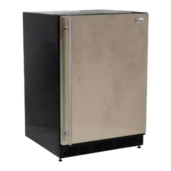
ZIB240P/ZIBS240P Bar Unit
DISCONNECT POWER CORD BEFORE SERVICING
IMPORTANT - RECONNECT ALL GROUNDING DEVICES
All parts of this appliance capable of conducting electrical current
are grounded. If grounding wires, screws, straps, clips, nuts or
washers used to complete a path to ground are removed for
service, they must be returned to their original position and
properly fastened.
ELECTRICAL SPECIFICATIONS
Temperature Control ...................................................................................39°F
Electrical Rating: 120V AC 60Hz .................................................... 2.0 Amp
Maximum Current Leakage .............................................................. 0.50 mA
Maximum Ground Path Resistance .........................................0.14 Ohms
NO LOAD PERFORMANCE
Control Position
and Ambient Temperature of:
Fresh Food, °F ................................................................ 33-45
Ice compartment, °F ...................................................(-5)-6
Percent Running Time, % ........................................ 35-45
REFRIGERATION SYSTEM
Refrigerant Charge (R134a) ................................................. 3.2 ounces
Compressor ................................................................................ 590 BTU/hr
Minimum Compressor Capacity
Vacuum .......................................................................................21 inches
Minimum Equalized Pressure
@70°F ............................................................................................... 37 PSIG
@90°F ............................................................................................... 40 PSIG
Evaporator
Process Tube
Dryer
Pub. No. 31-51547-1
06E-1794A
Technical Data
70°F
Capillary
Compressor
Condenser
IMPORTANT SAFETY NOTICE
This information is intended for use by individuals possessing
adequate backgrounds of electrical, electronic and mechanical
experience. Any attempt to repair a major appliance may result in
personal injury and property damage. The manufacturer or seller
cannot be responsible for the interpretation of this information,
nor can it assume any liability in connection with its use.
INSTALLATION
Clearance must be provided for air circulation
AT TOP ........................................................................................................................0
AT SIDES ....................................................................................................................0
AT REAR .........................................................................................................1 INCH
DOOR FRONT TO PROTRUDE
FROM CABINETS ............................................................... MIN. 1-3/4 INCH
90°F
33-45
(-5)-6
50-65
DC SIDE
FF NTC
BROWN or BLUE
BLUE or BROWN
EVAP
NTC
WHITE
DAMPER
2W
WHITE
HEATER
1
2
BLUE
3
WHITE
4
DAMPER
5
RED
6
N/C
KEY PLUG
BLACK or BROWN
FZ NTC
BLACK or BLUE
REED DOOR SW.
LOGIC
BOARD
RED
BLACK
EVAP. FAN
SERVICE BOARD - JUMPER CONFIGURATION
DC SIDE
LOGIC BD.
K11
NOTE: Remove Jumper J1 and J4. Jumpers J2 and J3 remain installed.
Three Serviceable thermistors: inside the unit, on the right wall, above
the top shelf, near the back wall.
Inside the unit, in the freezer compartment, on the right wall, near the
front, near the top.
Inside the unit, in the freezer compartment, behind the evaporator cover,
in the upper right corner of the evaporator.
Service Mode information on back of page.
WIRING DIAGRAM
POWER SUPPLY BOARD
K5
K1
BROWN
BLACK
1
LINE
1
WHITE
2
COM
NEUTRAL
2
GREEN/YELLOW
3
GND
3
BLUE
RED
4
COM
COMP
4
BLACK
K14
RED
1
+12V
WHITE
3
HEATER (COM)
K6
BLUE
1
CLOSE (COM)
BLACK
2
+18V
BROWN
K2
3
OPEN (COM)
WHITE
NEUTRAL
1
BLACK
2
RED
3
GREEN/YELLOW
K9
GND
4
WHITE
1
NEUTRAL
5
2
COM
LINE
BLACK
6
K11
BROWN
1
COM
BLACK
2
DATA
BLUE
3
CLK
WHITE
4
+5V
K3
BLACK
LIGHT
1
WHITE
K13
NEUTRAL
2
BROWN
1
+12V
BLUE
3
FAN (COM)
K4
WHITE
NEUTRAL
1
BLACK
HEATER
2
WHITE
NOTE: () = OPERATING DC VOLTAGES
FZ NTC
FF + EVAP NTC
K9
K5
J4
J1
J3
J2
K14
K13
DMPR.
EVAP.
HEATER
FAN
DAMPER
K6
06E-1794B
197D5892P003
AC SIDE
120V
WHITE
POWER
CORD
GREY
BLUE
COND. FAN
BLUE
OVER
RUN
PTCR
LOAD
CAP.
RED
COMPRESSOR
WATER
180-190 Ohms
VALVE
1
2
KEY PLUG
N/C
3
ICE
MAKER
4
5
KEY PLUG
N/C
6
LIGHT
15W
DRAIN TB
3.67W
HEATER
FILL TB
3.5W
HEATER
WHITE
FUSE
DEF
LINK
100W
HEATER
FAN
5.05W
HEATER
NOTE: WATTAGES @ 115V
AC SIDE
FILL TB + DEF
K4
HEATERS
LIGHT
K3
ICE MAKER
K2
POWER
K1
1547S
N.D. 06E-1794
Advertisement

Summary of Contents for Monogram ZIB240P
- Page 1 Technical Data ZIB240P/ZIBS240P Bar Unit 197D5892P003 DISCONNECT POWER CORD BEFORE SERVICING IMPORTANT SAFETY NOTICE IMPORTANT - RECONNECT ALL GROUNDING DEVICES This information is intended for use by individuals possessing All parts of this appliance capable of conducting electrical current adequate backgrounds of electrical, electronic and mechanical are grounded.
- Page 2 197D5892P003 Service Modes TO ENTER SERVICE MODE: Press and hold the (+), (-), and (ON/OFF) buttons simultaneously for 5 seconds. Display will show 3 numbers. First is the model number, verify this is 4 for the Bar unit. Second and third are software version. Use the (+) and (-) buttons to toggle through display codes.


