
Subscribe to Our Youtube Channel
Summary of Contents for PicoBox EMS-LTE
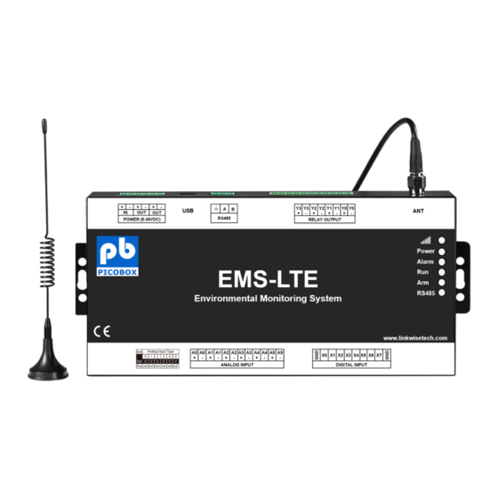
- Page 1 EMS-LTE User Manual Document No.: 2022-0001.2 EMS-LTE Environmental Monitoring System User Manual Please read this user manual carefully before using the device.
-
Page 2: Brief Introduction
The EMS-LTE supports data transmission and performs as Modbus Slave over GPRS/3G/4G network and RS485 serial port. Moreover, the EMS-LTE can be used as Modbus RTU Master to reading smart meters, I/O modules, PLC, and converts to SMS alert once triggered the... -
Page 3: Safety Directions
All wireless equipment might interfere network signals of the unit and influence its performance. Important Safety Instructions In these safety instructions, the word [device] refers to EMS-LTE and all its accessories. Read Instructions – Read all the safety and operating instructions before operating the device. •... - Page 4 EMS-LTE User Manual • Placing or Moving – Do not place this device on an unstable cart, stand, tripod, bracket or table. The device may fall and cause serious damage to itself and serious injury to others. A device and cart combination should be moved with care.
-
Page 5: Standard Packing List
EMS-LTE User Manual 3. Standard Packing List EMS-LTE Module; 12VDC Power Adaptor; GSM/3G/4G Antenna; PC Configurator USB Cable Note: The package does not include any SIM card. 4. Features • GSM/GPRS/3G/4G network communication, can be operated from anywhere, no distance limitation;... -
Page 6: Specifications
EMS-LTE User Manual 5. Specifications Item Reference Scope DC Power supply Standard adapter: DC 12V/2A Range 9-36VDC Power consumption Standby:12V/50mA; Working Max.: 12V/150mA GSM Frequency 850/900/1800/1900Mhz 3G/4G WCDMA/TDD-LTE/FDD-LTE SIM interface Supporting 3V and 1.8V SIM Card External antenna SMA Antenna interface, 50 Ohm, Gain: 3dB... -
Page 7: Led Indicator Definition
Alarm Alarm Indicator, alarm will ON and flick. Normally is OFF; Arm/Disarmed Indicator, Arm is ON, disarmed is OFF. EMS-LTE running status indicator, ON or OFF stands for EMS-LTE halted, flicks slowly stand for EMS-LTE running. RS485 When transmitting data by RS485, the LED will flick, otherwise, it is off. -
Page 8: Power Connector Definition
Switch it to upside is Set Mode, under this mode, the user can use PC Configurator via SET/RUN USB cable to configure the EMS-LTE Parameters or Read Parameter settings. Switch it to Downside is Run Mode, under this mode, the EMS-LTE is in Running mode. Tips: When device mode changed, need to switch off/on the device. -
Page 9: Digital Input Definition
EMS-LTE User Manual The 2 Channel Analog input. + stands for positive electrode, - stands for negative 1+/1- ~5+/5- electrode. Digital Input Definition Dry contact or wet contact, sampling frequency 200mS. Logic level: 0~0. 5V or short circuit treated as close, +3~30V or open circuits treated as open. - Page 10 EMS-LTE User Manual 7. Wiring...
-
Page 11: Settings & Operation
EMS-LTE User Manual 8. Settings & Operation The EMS-LTE is user-friendly design. The user can setup it or export historic data by the PC Configuration through USB cable, and upgrade firmware by USB port. The EMS-LTE also can be configured some basically parameters by SMS Commands, please refer to SMS Command List. - Page 12 Please click “EMS-LTE Configuration Tool” to run it. Enter the password, default is 1234. Then you can enter the configuration page as below: Notice: If display the below windows, then means the EMS-LTE connect to the PC failure. The reasons are below: USB Driver installation failure; USB Cable connection is disconnected;...
- Page 13 EMS-LTE User Manual 1234), click the "OK" to connect and start to program Details, please check the picture as below: Tips: If not connect successfully, will not enter into next step. Pls check if USB connect well, or COM port and password correct or not.
- Page 14 Note: Please select “Normal SIM Card (Call and SMS)” Save: Click it to save all of the PC Configurator parameters to the EMS-LTE; Import Configuration file: Click it to load additional configuration file to the Configurator; Export Configuration file: Click it to save the present configuration parameters as a profile for next...
-
Page 15: Basic Settings
The import and export configuration file are very useful while you need to program bulks of EMS-LTE with similar parameters. After programmed the first unit then you can export profile to save it, for the second EMS-LTE then you can load profile directly to save you time. - Page 16 EMS-LTE User Manual Synchronous device time: This is to setup the EMS-LTE time for daily report or other timers. After click Write the RTU Time, the EMS-LTE will be synchronous the same time as the PC. Device ID: Non-necessary. This is mainly for monitoring center to identify the EMS-LTE; If communicate via Modbus protocol, device ID only can be 1~247.
- Page 17 Timer Report: Tick it stands for Timer report SMS will send to this number. Arm/Disarm: Tick it stands for Arm or Disarm the EMS-LTE, will send SMS to this number. Low Signal: Tick it stands for while GSM/3G/4G Network signal strength lower than 14 will send SMS to this number.
-
Page 18: Access Control Setting
Access Control Setting This page is for setting which authorized number at what time can dial to the EMS-LTE and let the first channel (DO0) output a pulse output. Only when the output types of the first channel (DO0) setup as Open Door can dial to control it. - Page 19 EMS-LTE User Manual Tick the box ahead the User No. stands for enable the first Authorized number can dial in to let the first channel (DO0) output a pulse output. Start Time: Stands for from what time this authorized number can dial in to control it.
- Page 20 Siren: Tick it stands for while this digital input triggering, the DO that output type was setup as Siren will execute its output parameters. 24Hr: Tick it stands for no matter the EMS-LTE is in Arm or Disarmed mode, this digital input triggered will alarm.
- Page 21 AI Alarm Settings is the same: Notice: Call notification is not the pre-set voicemail notification. When there is an alarm, the EMS-LTE will generate a call to the pre-configured mobile number. The call does not contain any voice.
- Page 22 EMS-LTE User Manual Input Type: The user can choose the input type for related channel. Includes: Disable, 0~5V, 0~20mA, 4~20mA. 1) Disabled: Not use this channel. 2) 0~5V: For connecting transducers that output voltage 0~5V. Please remember to switch the related channel DIP switch to V side, see DIP Switch Definitions.
-
Page 23: Timer Settings
Siren: Tick it stands for while this input triggering, the DO that output type was setup as Siren will execute the its output parameters. 24Hr: Tick it stands for no matter the EMS-LTE is in Arm or Disarmed mode, this input triggered will alarm. - Page 24 Solution: Have no ticked the "Timer Reporting SMS Content" in first Basic Parameter Settings page. Logic Trigger Setting This page is for setup if what happen, then what action does the EMS-LTE should execute, it is a programmable logic event. Total can program up to 40 logic events for automatically control purposes.
-
Page 25: Modbus Rtu Slave Function
Slave longer than this value, will send SMS to authorize number. Modbus RTU Slave function: When RS485 as Modbus RTU Slave, can be connected to HMI, SCADA, DCS, PLC... as below: EMS-LTE I/O Register List and function code: Read Input Coil (Function Code 02: Read Coil) Register Address... - Page 26 EMS-LTE User Manual DIN4 value, when dry contact, NC=1, NO=0; When wet RTU DIN4 contract, 0~0.5V=1, 3~24V=0 DIN5 value, when dry contact, NC=1, NO=0; When wet RTU DIN5 contract, 0~0.5V=1, 3~24V=0 DIN6 value, when dry contact, NC=1, NO=0; When wet RTU DIN6 contract, 0~0.5V=1, 3~24V=0...
- Page 27 EMS-LTE User Manual Read and Write Holding Coil (Function Code 1, Function Code 5, Function Code 15.) Register Address Definition Description (Decimal) DO0 Value, Read/Write, 1=Close, 0=Open RTU DO0 DO1 Value, Read/Write, 1=Close, 0=Open RTU DO1 RTU DO2 DO2 Value, Read/Write, 1=Close, 0=Open...
- Page 28 EMS-LTE User Manual Slave Mapping list: This page is for adding, revising and deleting the slaves. Pls read the salves mapping list first before right click editing start. Slave Address: Stands for the Modbus RTU Slave ID. Data Type: Stand for "Boolean", "16 Bit", "32 Bit", "64 Bit".
-
Page 29: Slave Settings
Mxxx remote I/O module; When reading/writing device register 4~7, actually is reading/writing 6~9 register of smart meter. Slave Settings: Step1: Connect the slave to device EMS-LTE RS485 port. Find the slave port communication parameter and register address from user manual. Step2: Step3:... - Page 30 EMS-LTE User Manual Click Add Slave as below: If one slave have multi register, then need to add separately according to register type; For example, Mxxx remote I/O module, with digital and analog inputs, need to add the digital (Boolean) first, then add the analog (16 Bit).
- Page 31 EMS-LTE User Manual Click the "Edit Slave" to list the register according to chosen type (Boolean, 16 Bit, 32 Bit, 64 Bit). Boolean list edit as below: Address Mapping: Used for device to mapping slave register address. Channel Name: Setup channel name, alarm/recovery send "channel name + alarm content" to authorize number, need to tick Slave Alarm function in number setting page.
- Page 32 EMS-LTE User Manual Alarm Verify Time: Stands for unnormal value last time more than this value, will send alarm SMS to authorize number. Alarm SMS Content: When alarm happen, send SMS "channel name + content" to authorize number. Recovery SMS Content: When alarm recovery, send SMS "channel name + content" to authorize number.
- Page 33 When 16 Bit used for extend AIN inputs, can't convert acquisition ADC value to actual one according to range. For example: When Mxxx remote I/O module extend AIN, since Mxxx AIN register value is ADC, then device EMS-LTE read value is also ADC value. But DAM122 AIN value is calculated to actual value according to range, then stored in register, so the value device read, is also calculated value.
-
Page 34: Delete Slave
EMS-LTE User Manual Revise value, click OK, will write the value to slave corresponding register . And can mapping the register to device, read its function code for slave data current status, to check if set successfully or not. Step7: Click "Save"... - Page 35 Before reading data, pls read slave list from "Slave Mapping List" first, then can check slave current value in "Register" page: Network Settings This page used for setting device parameters connect to PICOBOX CLOUD via GPRS/3G/4G. Note: Please contact your sales representative for more information on package and configuration. Historical Record The device inbuilt 8G SD card, store alarm and historical records.
- Page 36 Save as CSV: Historical records export as CSV file. Erase RTU Records: Click this button will erase all device historical records, be careful. SMS Command List: The SMS commands will be used for remote control the EMS-LTE are below: 1) Commands error return SMS Event...
- Page 37 EMS-LTE User Manual 4) Arm/Disarm SMS Command SMS Command Return SMS Content password+AA Armed Disarm password+BB Disarmed 5) Set RTU time, format is 2015-05-22 15:20:30W01, the W01 stands for Monday, W07 stands for Sunday. SMS Command Return SMS Content password+Dxxxx-xx-xxTxx: xx: xxWxx...
- Page 38 EMS-LTE User Manual Delete password+B+series number Return all authorized user numbers 9) Setup Daily Report time SMS Command Return SMS Content Setup password+DR+series number+T+time Daily SMS Report at: xx:xx Notice: Series number =0~9, e.g.: 1234DR1T12:30 Inquiry password+DR Delete password+DRDEL 10) Inquiry DIN Status...
- Page 39 Return SMS Content password+GPRSonline GPRS always online 16) Clear/Inquiry Pulse Counter Value SMS Command Return SMS Content Clear Pulse Counter Value password+DIN0CLR Clear Successfully Inquiry Pulse Counter Value password+PR Counter Current Value: XX End of document! Thank you for purchasing Picobox EMS-LTE...
Need help?
Do you have a question about the EMS-LTE and is the answer not in the manual?
Questions and answers