Table of Contents
Advertisement
Advertisement
Table of Contents

Summary of Contents for M2M WebGate 3G
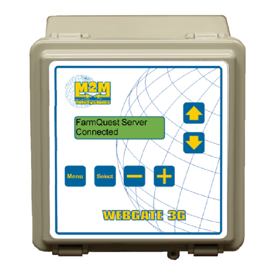
- Page 1 W W ebG Gate e 3G odule e nstalla ation g guide www.monitrol.com...
- Page 2 It is possible to remotely update the WebGate 3G firmware via the FarmQuest server. The WebGate 3G module will conserve all its data in the event of a power loss or outage. A total of 500 units (wireless or wired) may be connected to the WebGate 3G.
-
Page 3: Typical Installation Example
WebGate 3G Module Typical installation example Below is a typical installation diagram demonstrating network hierarchy with different M2M products and the different ways the SubConnect can be linked to the WebGate 3G. Figure 1 : Typical installation Page 3 of 16... -
Page 4: Unpacking
Unpacking Unpack the WebGate 3G module and check the contents. If they are damaged, contact the distributor in your area for information on returning the module. The package must contain the following standard items:... -
Page 5: Installation Steps
WebGate 3G Module Installation Steps 1. Attach the fasteners: Attach the four fasteners to the four support holes on the backside of the casing using the four screws included with the fasteners. Figure 2 : Mounting 2. Mount the casing to the wall: Insert screws into the fasteners’ adjustment slots. - Page 6 • Use a twisted pair to link terminals A&B and another twisted pair to link terminals C&D. It is not necessary that the WebGate 3G module be at the end of the loop. Note that if the control is equipped with only 3 terminals (A, B, C), terminals C&D of the WebGate 3G will be linked...
- Page 7 (see figure 4). Warning: • All RF-IN modules linked to the WebGate 3G must be set to the same RF Channel and RF Network number as the unit coordinating the Wi- Farm network (coordinator). Consult the SubConnect module or control instruction manual if needed.
-
Page 8: Activation Steps
WebGate 3G by viewing the “Network Settings, RF Address”. To access the installation menu, press and hold the “Select” button for about 3 seconds. Warning, as long as the WebGate 3G is in installation mode, the communication to the FarmQuest server is interrupted, therefore controls will no longer be checked. - Page 9 Once in the installation menu, use the “Menu” button to navigate through the installation menus. To view the number of units connected to the WebGate 3G, repeatedly press the “Menu” button until the display shows “Units Connected Total”. The total number of units appears on the second line of the LCD display.
- Page 10 WebGate 3G Module In the case of a wireless connection, make sure the channel (RF Channel) is set to the same value as the WebGate 3G on each unit. Also check the “RF Network”. All units must have the same “RF Network”...
- Page 11 WebGate 3G Module normally, but you will be unable to use FarmQuest services as long as your subscription to the FarmQuest server has not been completed. What to do if a “FarmQuest Server NOT FOUND, Check Internet Connectivity” message appears? : The physical link with the Internet access equipment is not working.
-
Page 12: Figure 3 : Webgate 3G Wiring Diagram
6. The “RESET CONTROL” output is used to connect a “Controlled AC Outlet” used to interrupt Internet access equipment power for 5 seconds when there is no Internet communication for 20 minutes between the WebGate 3G and FarmQuest. Page 12 of 16... -
Page 13: Figure 4 : Electronic Cards
WebGate 3G Module Figure 4 : Electronic cards BOTTOM ENCLOSURE INSIDE COVER RESET 5Vdc/1A ETHERNET CONTROL INPUT 1. Ethernet module emplacement. 2. “Reset Control” terminal for “Controlled AC Outlet” module connection. 3. 5VDC power connector. 4. RF-IN wireless card connector. -
Page 14: Specifications
WebGate 3G Module Specifications DESCRIPTION VALUE Storage temperature -4°F to 131°F (-20°C to 55°C) Operation temperature 32°F to 122°F (0°C to 50°C) Humidity 90% maximum non-condensing Weight 1,4 lb (0,6 Kg) Dimensions 6” x 6” x 3 3/4” (15 cm x 15 cm x 9,5 cm) -
Page 15: Table Of Contents
TABLE OF FIGURES Figure 1 : Typical installation ..................... 3 Figure 2 : Mounting ......................5 Figure 3 : WebGate 3G wiring diagram ................12 Figure 4 : Electronic cards ....................13 Page 15 of 16 www.monitrol.com... -
Page 16: Limited Warranty
WebGate 3G VER : 1.1a July 8, 2011 Page 16 of 16...
Need help?
Do you have a question about the WebGate 3G and is the answer not in the manual?
Questions and answers