Table of Contents
Advertisement
Quick Links
Advertisement
Table of Contents

Subscribe to Our Youtube Channel
Summary of Contents for Camlock Systems ACS-200
- Page 1 ACS-200 Smart integration hub Quick Start Guide Version: 0.3 Date: 13-06-2022...
-
Page 2: Table Of Contents
ACS-200 Quick Start Guide Contents Getting Started ......................................... 2 Connections and Wiring ..................................2 Communicating with the ACS-200 ............................3 Serial Communication ................................... 3 2.1.1 Serial Terminal Software ..............................3 2.1.2 Connecting to the Unit ................................3 2.1.3 Serial Port Settings ..................................3 2.1.4... -
Page 3: Getting Started
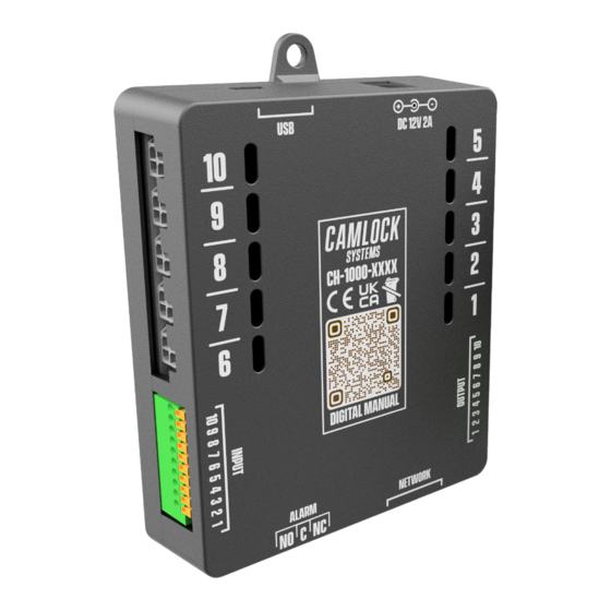
Quick Start Guide Getting Started Connections and Wiring Connect the required number of locks to the ACS-200. Note that only 3-Wired, 12 Volt Rated, Negatively Triggered Electronic Locks manufactured by Camlock Systems are currently compatible with the ACS-200. The connector, pinout and wiring diagram is given below. Take extra care with the wire colours and positions, as wrong wiring can damage the locks. -
Page 4: Communicating With The Acs-200
COM port the ACS-200 is connected to. All available COM ports will appear in the list of ports as COMx, x being the port number (COM4 in the example below). The ACS-200 will appear on the list of devices as USB-SERIAL CH340. -
Page 5: Terminal Window Settings
2.2.3 Initialisation Once everything is connected and setup correctly, the ACS-200 will initialise and report the status of the system including settings and states of all the ports as shown below. Please note that all unconnected ports as well as locks left in the open position during... -
Page 6: Sending Commands
ACS-200 Quick Start Guide 2.2.4 Sending Commands To send commands, just type in the required command from the list in the following section into the serial terminal window. The Enter Key may or may not need to be pressed depending on the software used. If using Tera Term, you can also use the Broadcast Command function under the Control Menu. -
Page 7: Ethernet Communication
2.3.3 Configuring and Connecting the Units Once the IP addresses and Port number have been assigned to all the ACS-200 units, they will need to be configured with their individual IP address, the IP address of the controlling computer and the UDP Port number for the system. -
Page 8: Communicating With The Units
For UDP communication, enter the destination IP address of the desired ACS-200 unit and the UDP Port number in the settings of the UDP Packet Software. Then send a command from the list in the following section to check if you get a response back from the ACS-200 unit. -
Page 9: Functions, Commands And Errors
ACS-200 Quick Start Guide 3 Functions, Commands and Errors 3.1 Functions List Function Description unlock Opens a lock or closes it when hold feature is on and the lock is already open interlock Interlocking allows only one lock to be opened at any given time... -
Page 10: Error Codes List
ACS-200 Quick Start Guide 3.3 Error Codes List Error code Description Acknowledged (No Error) Invalid Command Invalid Parameter Interlocking On/Lock Open Lock Disabled Door Open Alarm Intrusion Alarm 3.4 State Codes List State code Description Off or closed On or open Disabled 3.5 State Report Breakdown...
Need help?
Do you have a question about the ACS-200 and is the answer not in the manual?
Questions and answers