Table of Contents
Advertisement
Quick Links
Advertisement
Table of Contents

Summary of Contents for P&B MR-REF
- Page 1 MR-REF & MR-REF3 Technical Manual Issue 3, November 2013...
-
Page 3: Table Of Contents
6.10. Last Five Faults...................................... 21 6.11. Stats Info........................................ 22 6.12. Calibration Menu....................................22 6.13. Disturbance Recording (OPTIONAL)..............................23 7. Menu Tree Structure ......................................24 8 MR-REF & MR-REF3 Setting Sheets ................................. 25 8.1. MR-REF & MR-REF3 System Settings Summary............................25... - Page 4 Issue 3, November 2013 8.2. MR-REF & MR-REF3 Control Setting Summary............................26 8.3. MR-REF & MR-REF3 Protection Setting Summary............................27 8.4. MR-REF & MR-REF3 Blank Protection Setting Summary..........................27 Appendix 1 ........................................... 28 MR-REF – MR-REF3 Installation..................................28 Appendix 2 ...........................................
-
Page 5: P&B Mr-Ref & Mr-Ref3
MR-REF & MR-REF3 monitors the earth current/s by means of conventional ring type current transformers with typically 1A or 5A secondary outputs. This measured current is then used by the MR-REF & MR-REF3 to determine tripping or alarm functions in order to interrupt the main switching device and protect the circuit or transformer from damage. -
Page 6: Principle Of Operation
P&B application Note MR901 Unbiased Differential Three MR-REF relays or one MR-REF3 are required to achieve full protection. Each with stabilizing resistors and possibly a voltage dependent non-linear resistor. Page 2... -
Page 7: Restricted Earth Fault Protection For Transformers
MR-REF & MR-REF3 Technical Manual Issue 3, November 2013 Restricted Earth Fault Protection for Transformers. Application for 3 & 4 wire systems (System Earth at Switchboard) Application for “5” wire systems (earth & Neutral connections both available at the transformer) -
Page 8: Displayed Feeder Data
MR-REF & MR-REF3 Technical Manual Issue 3, November 2013 1.2 Protective Functions. Restricted Earth Fault Protection Serial Timeout protection Internal Error Protection 1.3 Displayed Feeder Data. Restricted Earth Fault Current/s No of Operations Accumulated Current/s at Trip Digital Input 1 Status... -
Page 9: Technical Specification
MR-REF & MR-REF3 Technical Manual Issue 3, November 2013 2. Technical Specification. Power Supply. & L UXILIARY OWER UPPLY OLTAGE OWER UPPLY AC Nominal Range 80 – 265V AC / DC Range 24V AC / 24-48V DC (Low Voltage Power Supply Optional Extra) -
Page 10: Environmental Tests
MR-REF & MR-REF3 Technical Manual Issue 3, November 2013 3. Environmental Tests. CLIMATIC EST STANDARD EVERITY LEVEL Temperature Dry Cold IEC 60068-2-1 -20 deg C ,96 hrs Operational Temperature Dry Cold IEC 60068-2-1 -40 deg C , 96hrs Transportation & Storage... -
Page 11: Inputs And Outputs
4.1. Power Supply Live. The MR-REF & MR-REF3 requires a permanent AC or DC Voltage to supply the unit as specified by the relay rating label. This auxiliary live is also used as the source voltage to power the digital inputs. -
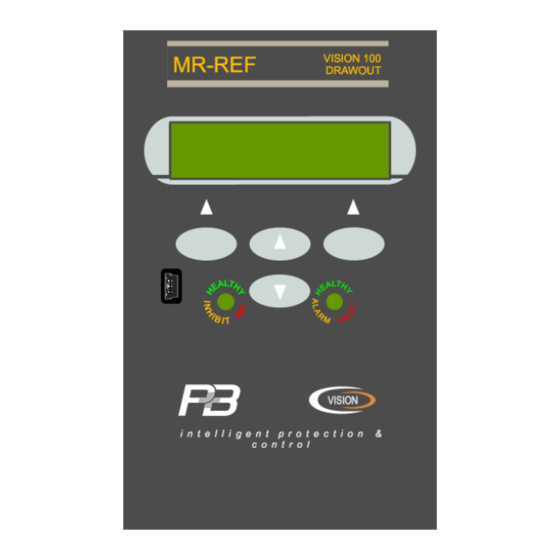
Page 12: Faceplate Functions
Issue 3, November 2013 5. Faceplate Functions. The MR-REF & MR-REF3 faceplate has been designed to provide an intuitive easy to use display allowing access to all the required information an operator would require. This is achieved by using tri-colour LED indications and a LCD display driven by 4 function keys. -
Page 13: Lcd Display
MENU Upon power up the MR-REF & MR-REF3 software version screen appears for a few seconds. The screen shows the software version and the unit type, which should be noted in all correspondence regarding the relay. After the Introduction screen disappears then the initial display scroll page appears. -
Page 14: Display Scroll
MR-REF & MR-REF3 Technical Manual Issue 3, November 2013 6.2. Display Scroll. Examples of the Display Scroll screens. Restricted EF Iref 0.00A Hlth MENU MENU MENU MENU Al No Alarm MENU The <UP> and<DOWN> buttons will allow each of the above screens to be displayed in turn returning to the first screen and will loop continuously. -
Page 15: Feeder Settings
MR-REF & MR-REF3 Technical Manual Issue 3, November 2013 6.3. Feeder Settings. This screen allows access to the Feeder Settings of the relay. The EF CT Primary can be viewed and set. The list of values that are available to be changed can be scrolled through by pressing the UP and DOWN buttons. -
Page 16: Serial Settings
Feeder Number. This setting range 1 to 32, with a default setting of 1, identifies the MR-REF & MR-REF3 unit to the Xcell unit (or any Master device connected to the Data highway) to which the RS485 port is connected. When updating firmware the auto program mode requires the drive number to be 1. - Page 17 This setting need only be used in order to limit the amount of data traffic on a RS485 network. Dynamic data can change rapidly, this setting allows the MR-REF & MR-REF3 to limit the number of updates it makes to its Fast Scan values.
-
Page 18: I/O Settings (Input / Output Settings)
6.5.1 Digital Inputs The MR-REF & MR-REF3 provides 2 digital inputs which can be configured to one of the functions described below. Otherwise the digital input defaults are Not Used. Reset Fault. -
Page 19: Relay Outputs
6.5.2 Relay Outputs The MR-REF & MR-REF3 provides 4 changeover contact relay outputs, three of which can be configured to one of the functions described below. Otherwise the programmable relay output defaults are Not Used. Relay 1 is fixed as Trip Trip. -
Page 20: System Settings
Time Sync Delay. The MR-REF & MR-REF3 can be time synchronised by either, Chronovision which is a GPS based device which sits on the RS485 network and synchronises the time and date of each connected unit, or via broadcast command on the daisy chained RS485 modbus network. -
Page 21: Disturbance Recording Activation Key
To help extend the life of the LCD we can power the display down if the application suits. The screen will power down after the set time from the last key press. The MR-REF & MR-REF3 will still operate and can be remotely controlled via digital inputs or the serial interface. -
Page 22: Protect Settings
MR-REF & MR-REF3 Technical Manual Issue 3, November 2013 6.7. Protect Settings. This menu allows the user to configure all of the protective functions. DISPLAYED: FULL DETAIL: Restricted Earth Fault Ser Tmout Serial Timeout Intnl Err Internal Error Each function can be set to Alarm and / or Trip and / or Block or left as an unused function, disabled. The resets for each are protective function are independently configurable as are the trip levels and trip times. -
Page 23: Function
A Trip is considered as a high level function. If the function activates it will be recorded as part of the trip history and cause the MR-REF & MR-REF3 to enter a trip state; the fault will be displayed in the active faults page and the unit will automatically display that page, the right hand LED will give a Trip indication (red colour). -
Page 24: Restricted Earth Fault
For a set period of inactivity on the rear communication port the unit can be configured to take some action in the event. It is worth noting that the MR-REF & MR-REF3 device is slave to any host system, the unit will not send information via the serial port unless it has been requested by a master device. -
Page 25: Trip History
MR-REF & MR-REF3 Technical Manual Issue 3, November 2013 6.8. Trip History. Trip History This screen allows access to the relays Trip History Trip Cause data. No Data Up to 32 Trip events can be registered in this menu screen, starting with the most recent to last available most recent trip). -
Page 26: Stats Info
MR-REF & MR-REF3 Technical Manual Issue 3, November 2013 6.11. Stats Info. If the Password is set to enabled, the password will be requested here to allow access to this menu. Stats Info No. of Trips This screen allows access... -
Page 27: Disturbance Recording (Optional)
MR-REF & MR-REF3 Technical Manual Issue 3, November 2013 6.13. Disturbance Recording (OPTIONAL). Disturbance and fault recording is a very effective tool for personnel to analyses the performance of the power system and related equipment during and after a major disturbance. -
Page 28: Menu Tree Structure
MR-REF & MR-REF3 Technical Manual Issue 3, November 2013 INITIAL MENU 7. Menu Tree Structure Restricted Earth Current 1, Restricted Earth Current 2 MR-REF3 only, Restricted Earth Current 3 MR-REF3 only, MENU DISPLAY SCROLL DI1, DI2, Trip Status, Alarm Status,... -
Page 29: Mr-Ref & Mr-Ref3 Setting Sheets
MR-REF & MR-REF3 Technical Manual Issue 3, November 2013 8 MR-REF & MR-REF3 Setting Sheets 8.1. MR-REF & MR-REF3 System Settings Summary. Range Step Default User Setting Serial Settings Serial Enabled / Disabled Enabled Drive Number 1-32 RS485 Baud Rate... -
Page 30: Mr-Ref & Mr-Ref3 Control Setting Summary
MR-REF & MR-REF3 Technical Manual Issue 3, November 2013 8.2. MR-REF & MR-REF3 Control Setting Summary. Range Step Default User Setting Digital Inputs Not Used / Reset / Block / Dig_In 1 Reset Fault Not Used / Reset / Block /... -
Page 31: Mr-Ref & Mr-Ref3 Protection Setting Summary
Reset Trip Level 1-200% Restricted Earth Fault Trip Time 0.04-0.5s 0.01s Serial Timeout Timeout In 1-120s Internal Error 8.4. MR-REF & MR-REF3 Blank Protection Setting Summary. # Selectable ! Fixed ANSI Available Available Protective Function Variable User Settings Action Reset... -
Page 32: Mr-Ref - Mr-Ref3 Installation
0.5 – 0.6 Nm The MR-REF & MR-REF3 has been designed for installation on to open type panels, for use on the flat surface of a type 1 enclosure and for installations where the ambient temperature does not exceed 60... -
Page 33: Termination Numbers Mr-Ref Version
MR-REF & MR-REF3 Technical Manual Issue 3, November 2013 Appendix 2 Termination Numbers MR-REF Version Page 29... -
Page 34: Mr-Ref Version Schematic Diagrams
MR-REF & MR-REF3 Technical Manual Issue 3, November 2013 Appendix 3 MR-REF Version Schematic Diagrams. Conventional Protection Class Ring-Type Current Transformer of 1A or 5A Secondary rating are common and can be connected directly to the CT inputs of MR-REF. Page 30... -
Page 35: Version
MR-REF & MR-REF3 Technical Manual Issue 3, November 2013 Version Appendix 4 Termination Numbers MR-REF3 Version Page 31... -
Page 36: Mr-Ref3 Version Schematic Diagrams
MR-REF & MR-REF3 Technical Manual Issue 3, November 2013 Appendix 5 MR-REF3 Version Schematic Diagrams. Conventional Protection Class Ring-Type Current Transformer of 1A or 5A Secondary rating are common and can be connected directly to the CT inputs of MR-REF3. -
Page 37: Factory Default Procedure
MR-REF & MR-REF3 Technical Manual Issue 3, November 2013 Appendix 6 Factory Default Procedure If for any reason the unit is required to be set to factory defaults the following method can be applied. Power down the relay unit. •... -
Page 38: Handling Guidelines
P&B are committed to manufacturing practices which do not result in pollution or cause damage to the environment. As the MR-REF & MR-REF3 contains a non rechargeable battery we would recommend safe disposal of equipment at the end of its life inline with local laws.
Need help?
Do you have a question about the MR-REF and is the answer not in the manual?
Questions and answers