Table of Contents
Advertisement
Quick Links
Your best partner for power
Ultra UL1741
Pure Sine Wave Inverter Chargers
User's Guide
Model Numbers
FULAGDA1512A, FULAGDA2524A, FULAGDA3524A
FULAGDA4524A, FULAGDA3548A, FULAGDA4548A
FULAGDA6048D, FULAGDA1512T, FULAGDA2524T
FULAGDA3524T, FULAGDA4524T, FULAGDA3524D
FULAGDA3548D, FULAGDA4524D, FULAGDA4548D
Advertisement
Table of Contents

Summary of Contents for FOXPOWER Ultra UL1741
- Page 1 Your best partner for power User's Guide Ultra UL1741 Model Numbers Pure Sine Wave Inverter Chargers FULAGDA1512A, FULAGDA2524A, FULAGDA3524A FULAGDA4524A, FULAGDA3548A, FULAGDA4548A FULAGDA6048D, FULAGDA1512T, FULAGDA2524T FULAGDA3524T, FULAGDA4524T, FULAGDA3524D FULAGDA3548D, FULAGDA4524D, FULAGDA4548D...
- Page 2 Copyright © 2017-2018 Foxpower Technology. All Rights Reserved. All trademarks Information about your system are owned by Foxpower Technology or its affiliated companies. As soon as you open your product, record the following informtion Exclusion for documentation and be sure to keep your proof of purchase...
- Page 3 IMPORTANT: These notes describe things which are important for you to know, however, they are not as serious as a caution or warning. Conventions Used Related Information The following conventions are used in this guide. You can find more information about Foxpower-branded products and services at www.fox-power.com...
- Page 4 Ultra UL1741, READ ALL instructions and cautionary markings on or provided with the inverter/charger, the batteries, and all appropriate • Do not expose the Ultra UL1741 to rain, snow, spray, or bilge water. sections of this guide. This inverter/charger is designed for marine applications only when additional drip protection is installed in certain orientations.
- Page 5 NOTES: DANGER FIRE AND BURN HAZARD 1. Follow these instructions and those published by the battery manufacturer and the manufacturer of any equipment you intend to • Do not cover or obstruct the air intake vent openings and/or install in a use in the vicinity of the battery.
- Page 6 Failure to follow these instructions can result in death or serious injury. NOTES: 1. Mount and place the Ultra UL1741 Inverter/Charger unit away from batteries in a well ventilated compartment. 2. Always have someone within range of your voice or close enough to come to your aid when you work near a lead-acid battery.
- Page 7 • Make sure the voltage of the batteries matches the output voltage of • Never place the Ultra UL1741 Inverter/Charger unit directly above the inverter/charger. batteries; gases from a battery will corrode and damage the inverter/ charger.
- Page 8 Canadian standards. For more information see “Regulatory Approvals” on the Specifications section in the Owner’s Guide. The Ultra UL1741 Inverter/Charger is intended to be used for mobile or commercial applications. This inverter/charger is designed for marine applications only when additional drip protection is installed in certain orientations.
-
Page 9: Table Of Contents
Two Key Performance Factors Size and Length of DC Cables Mounting Location of the Ultra UL1741 Planing Preparations AC, DC, and Network Components Unpacking and Inspection the Ultra UL1741 Inverter/Charger Installation Tools To unpack and inspect Installation Materials Installation Step 1: Choosing a location for the Inverter/Charger... - Page 10 Step 2: Mounting the Inverter/Charger Considerations To mount the Inverter/Charger Step 3: Connecting the AC Input and AC Output Wires General AC Wiring Considerations Connecting AC Input and AC Output Wires Step 4: Connecting the DC Cables DC Connection Precautions Recommended Cable Sizes and Lengths and Fuse Size Guidelines for Routing the DC Cables Connecting the DC Cables to the Inverter/Charger...
-
Page 11: General Information
General Information Ultra UL1741 series pure sine wave inverter charger is a combination of an inverter, battery charger and AC auto-transfer switch into one complete system with a peak DC to AC conversion efficiency of 90%. It is packed with unique features and it is one of the most advanced inverter charger in the market today. -
Page 12: Application
High efficiency design. Basic Protection Features l 13Vdc battery recovery point, dedicated for renewable energy The Ultra UL1741 inverter charger is equipped with extensive protections systems. against various harsh situations/faults. These protections include: l 8 pre-set battery type selector plus De-sulphation for totally flat l AC input over voltage protection/ AC input low voltage protection batteries. -
Page 13: Key Features Explained
Key Features Explained Multi-Stage Charger Bulk Charging: This is the initial stage of charging. While Bulk Charging, the charger supplies the battery with controlled constant current. The charger will remain in Bulk charge until the Absorption charge voltage (determined by the Battery Type selection) is achieved. - Page 14 Charging depleted batteries The Ultra UL1741 series inverter allows start up and through power with depleted batteries. For 12VDC models: after the battery voltage goes below 10V and the power switch is kept in the "ON"...
-
Page 15: Charing Current For Each Model
Charing Current For Each Model Transfer Rated Battery Swift Power Transfer Model Power Voltage Current While in the Standby Mode, the AC input of the inverter is continually FULAGDA1512A/T 1500W 12Vdc monitored. Whenever AC power falls below the low AC voltage trip FULAGDA2524A/T 2500W 24Vdc... - Page 16 Battery Temperature Sensor Applying the proper charge voltage is critical for achieving optimum IMPORTANT: If the battery temperature is allowed to fall to extremely battery performance and longevity. The ideal charge voltage required by cold temperatures, the inverter with a BTS may not be able to properly batteries changes with battery temperature.
- Page 17 Foxpower Ultra UL1741 pure sine wave inverter charger models.Instead of When the inverter goes to low battery alarm, it can send a signal to simply bypassing the input AC to power the loads, the Ultra UL1741 series start a generator and turn the generator off after battery charging is inverter stabilizes the input AC voltage to a range of 120V±10%.
- Page 18 Remote Control Figure 6 Apart from the switch panel on the front (or top) side of the inverter, an extra LCD remote switch panel (Figure 7) connected to the remote port at the DC side of the inverter through a standard Ethernet cable can also control the operation of the inverter.
-
Page 19: Power Saver
Power Saver There are two different working statuses for our Ultra UL1741 inverter: "Power On" and "Power Off". When the power switch on power switch panel (Figure 2) is in "Unit Off" position, the inverter is powered off. When the power switch is turned to either of "Power Saver Auto" or "Power Saver Off", the inverter is powered on. -
Page 20: Audible Alarm
Audible Alarm Battery Voltage Low LCD displays "BATT LOW", and the buzzer beeps Allow at least 30CM of clearance around the inverter for air flow. Make 0.5s every 5s sure that the air can circulate freely around the unit. Battery Voltage High LCD displays "BATT HIGH", and the buzzer beeps Variable speed fan operation is required in invert and charge mode. -
Page 21: View Of Front Panel
View of Front Panel (For FULAGDA1512T, FULAGDA2524T, FULAGDA3524T, FULAGDA4524T) Inverter Mode LED fault Charger Mode LED Fault LED Power ON/OFF Enter Key Page Up Page Down Function/ESC Key 1. AC Status & Input Voltage AC: Normal "AC: abnormal" will be displayed when I/P-V: 120V AC input is not qualified 2. - Page 22 View of Front Panel (For FULAGDA1512A, FULAGDA2524A, FULAGDA3524A, FULAGDA4524A, FULAGDA3548A, FULAGDA4548A, FULAGDA6048D, FULAGDA3524D, FULAGDA4524D, FULAGDA3548D, FULAGDA4548D) Power ON/OFF: 1. Power Saver Auto: Turn on Unit and in Power Saver Mode 2. Unit off: Turn off unit Inverter Mode LED fault Charger Mode LED Fault LED Enter Key...
-
Page 23: Ac And Dc Side Panels
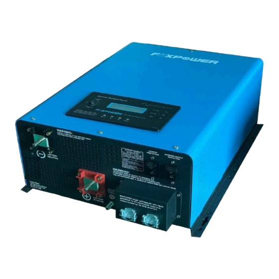
AC and DC Side Panels The DC side of the Ultra UL1741 has the equipment ground lug, the Item Description Negative (–) DC terminal (black). Use a qualified personnel positive (+) battery terminal, and the negative (-) battery terminal plus the for connecting cables. -
Page 24: Materials List
Materials List The Ultra UL1741 ships with the following items: • One Ultra UL1741 unit • Installation Guides • DC terminal covers (one red, one black) NOTE: If any of the items are missing, contact customer service or any authorized Foxpower dealer for replacement. -
Page 25: Installation Information
Installation Information Before You Begin the Installation Installation Codes Before beginning your installation: Applicable installation codes vary depending on the specific location and application of the installation. Some examples are: • Read the entire Installation Guide so you can plan the installation from beginning to end. -
Page 26: Planing The Installation
Mounting Location of the Ultra UL1741 To choose an appropriate location for mounting the inverter/charger, see "Step 1: Choosing a Location for the Inverter/Charger" on page 21. -
Page 27: Planing Preparations
Planing Preparations AC, DC, and Network Components For a successful installation, you need to plan for AC, DC, and network components of the power system. The AC and DC components are described in this section and illustrated in Figure 9 on page 17. AC components include: •... - Page 28 Conduit Box Design Conduit Box...
- Page 29 Basic Configulation...
-
Page 32: Unpacking And Inspection The Ultra Ul1741 Inverter/Charger
Installation Tools Installation Materials You will need the following tools to install the Ultra UL1741 and the battery You will need the following materials to complete your installation: temperature sensor. -
Page 33: Installation
Installation Step 1. Choosing a Location for the Inverter/Charger CAUTION CAUTION: Some models of the inverters are heavy. Use proper lifting DANGER techniques during installation to prevent personal injury. FIRE AND EXPLOSION HAZARD Do not install this equipment in compartments containing batteries or flammable materials, or in locations that require ignition-protected WARNING equipment because this equipment contains components that could... -
Page 34: Step 2: Mounting The Inverter/Charger
Before mounting the Ultra UL1741, take the following two factors into account. To mount the inverter/charger: 1. The weight of the Ultra UL1741 inverter/charger requires two people to 1. Remove the inverter/charger from its shipping container. install it. 2. Verify that all components are present. - Page 35 In order to mount the inverter securely, the surface and the mounting hardware must also be able to support at least twice the weight of the inverter. To meet regulatory safety requirements, the Ultra UL1741 Series must be mounted: Figure 10...
-
Page 36: Step 3: Connecting The Ac Input And Ac Output Wires
Step 3: Connecting the AC Input and AC Output Wires IMPORTANT: wiring the output inverter to back to the main panel DANGER could result in ground bonding to occur in multiple locations in contravention of applicable wiring codes and may result in nuisance FIRE, ELECTRICAL SHOCK, AND ENERGY HAZARDS tripping of Ground fault protection equipment. -
Page 37: Connecting Ac Input And Ac Output Wires
Connecting AC Input and AC Output Wires (Single Phase) Figure 14 shows the wiring compartment, which contains a terminal block NOTICE (used to wire the AC input and AC output connections). EQUIPMENT DAMAGE Connect wires to the correct terminals in the terminal block that is split into INPUT and OUTPUT sections. - Page 38 Connecting AC Input and AC Output Wires (Split Phase) Daul-Phase Wiring 240Vac split phase Input: Hot line + Hot Line + Ground Output: Hot line + Hot Line + Neutral Daul-Phase Wiring 120Vac split phase Input: Hot line + Hot Line + Ground Output: Hot line + Ground + Neutral Remark: In such cases, each output hot line can only carry a half the rated capacity Max...
-
Page 39: Step 4: Connecting The Dc Cables
Step 4: Connecting the DC Cables DC Connection Precautions Battery cables must have crimped (or preferably, soldered and crimped) DANGER copper compression lugs unless aluminum mechanical lugs are used. Soldered connections alone are not acceptable. High quality, UL-listed ELECTRICAL SHOCK HAZARD battery cables are available .These cables are color-coded with pressure Connect and disconnect DC wiring only after opening the disconnect crimped, sealed ring terminals. -
Page 40: Guidelines For Routing The Dc Cables
Guidelines for Routing the DC Cables Connecting the DC Cables to the Inverter/Charger Follow these guidelines to ensure maximum performance. WARNING WARNING ELECTRICAL SHOCK AND FIRE HAZARD FIRE HAZARD • Route the cables away from sharp edges that might damage the Use only appropriately sized copper cable. -
Page 41: To Connect The Dc Cables
To connect the DC cables: IMPORTANT: The next step is the last cable connection you need to 1. Route the DC cables from the battery bank to the inverter/ charger. make. A spark is normal when the DC disconnect switch is turned on or Observe the "Guidelines for Routing the DC Cables"... -
Page 42: Dc Grounding
DC Grounding The Chassis Ground point on the inverter/charger is used to connect the chassis of the inverter/charger to your system’s DC grounding point, as required by regulations for some installations. Use copper wire that is either bare or provided with green insulation. The grounding guideline given below assumes you are using the code- compliant DC supply cable and fuse sizes indicated on page 24. -
Page 43: Inverter/Charger Physical Specifications
Inverter/Charger Physical Specifications Top View (FULAGDA1512A, FULAGDA2524A, FULAGDA3524A, FULAGDA4524A, FULAGDA3548A, FULAGDA4548A) 460mm Side View (FULAGDA1512A, FULAGDA2524A, FULAGDA3524A, FULAGDA4524A, FULAGDA3548A, FULAGDA4548A) 360mm... - Page 44 Top View (FULAGDA3548D,FULAGDA4548D, FULAGDA6048D, FULAGDA3524D, FULAGDA4524D) 460mm Side View (FULAGDA3548D,FULAGDA4548D, FULAGDA6048D, FULAGDA3524D, FULAGDA4524D) 360mm...
- Page 45 Top View (For FULAGDA1512T, FULAGDA2524T, FULAGDA3524T, FULAGDA4524T) 460mm Side View (For FULAGDA1512T, FULAGDA2524T, FULAGDA3524T, FULAGDA4524T) 360mm...
-
Page 46: Battery Information
A typical marine or RV battery rated for 100 Ah can deliver 5 amps for type selected for use with the Ultra UL1741. The batteries are the most 20 hours (5 amps × 20 hours = 100 Ah). This same battery can deliver a... -
Page 47: Estimating Battery Requirements
3. Obtain the amp-hours that the appliance requires by dividing that life is directly dependent on how deeply the battery is discharged. The amount by 10 (the factor for the Ultra UL1741, which is a 12-volt system): deeper the discharge, the shorter the battery life. -
Page 48: Battery Banks
Battery Sizing Example (A) Power Consumption (Watts) (B) Operating Time per Day Daily watt-hours needed Applicance (Hours) for this appliance (= A × B) TV & VCR 2 hours 400 Wh 200W Small microwave oven 15 min = 1/4 hour 200 Wh 800W 3 lamps, 60 W each... - Page 49 Battery Sizing Worksheet (A) Power Consumption (Watts) (B) Operating Time per Day Daily watt-hours needed Applicance (Hours) for this appliance (= A × B) hours hours hours hours hours Total daily watt-hours of AC load x Number of days between charges =Total watt-hours of AC load between charges Battery Ah used between charges (divide by 10 for 12volt system;...
-
Page 50: Battery Cabling And Hook-Up Configurations
Battery Cabling and Hook-up Configurations Several smaller batteries can be connected to create a battery bank of Battery Parallel Connection substantial size. You can connect batteries in three ways: in parallel, series, or series-parallel. Batteries are connected in parallel when all the positive terminals of a To make a larger battery bank, connect individual batteries with heavy group of batteries are connected and then, separately, all the negative cables. -
Page 51: Battery Series Connection
Battery Series Connection Battery Series-Parallel Connections When batteries are connected with the positive terminal of one battery to As the name series-parallel implies, both the series and parallel the negative terminal of the next battery, they are connected in series. In a configurations are used in combination. -
Page 52: Troubleshooting Guide
Troubleshooting Guide Troubleshooting contains information about how to troubleshoot possible error conditions while using the Ultra UL1741 Series Inverter Charger Symptom Possible Cause Recommended Solution Inverter will not turn on during Batteries are not connected, loose Check the batteries and cable connections. - Page 53 *The reason for the noise from transformer and/or case When in inverter mode sometimes the transformer and/or case of the inverter may vibrate and make noise. If the noise comes from transformer: According to the characteristics of our inverter, there is one type of load which most likely may cause rattles of transformer.
-
Page 54: Specification
Specification FULAGDA1512A FULAGDA2524A FULAGDA3524A FULAGDA4524A Electrical Specifications - Inverter FULAGDA3548A FULAGDA4548A FULAGDA6048D FULAGDA1512T FULAGDA2524T FULAGDA3524T FULAGDA4524T Coninuous output power 1500W 2500W 3500W 4500W 3500W 4500W 6000W(240Vac) 3000W(120Vac) Surge Rating (20s) 4500W 7500W 10500W 13500W 10500W 13500W 18000W(240vac) 9000W (120vac) Capable of starting electric motor 1.5HP 5HP (240vac) 2HP (120vac) Pure sine wave/same as input(bypass mode) - Page 55 FULAGDA1512A FULAGDA2524A FULAGDA3524A FULAGDA4524A Electrical Specifications - Charger FULAGDA3548A FULAGDA4548A FULAGDA6048D FULAGDA1512T FULAGDA2524T FULAGDA3524T FULAGDA4524T Input voltage range Narrow: 100-145Vac; Wide: 90-145Vac 200-254Vac/150-260Vac Input frequency range Narrow:47-55±0.3Hz for 50Hz,57-65±0.3Hz for 60Hz Wide: 42-70±0.3Hz plus for 50Hz/60Hz Input frequency range Max charge current Charger efficiency Over charge current shutdown 15.7V...
- Page 56 FULAGDA1512A FULAGDA2524A FULAGDA3524A FULAGDA4524A Electrical Specifications - General FULAGDA3548A FULAGDA4548A FULAGDA6048D FULAGDA1512T FULAGDA2524T FULAGDA3524T FULAGDA4524T Versatile mounting Mounting method Display LCD+LED status display 2 Years Warranty Automatic Generator Start (AGS) Option Battery termperature sensor Option Remote control panel Regulatory and environment compliance UL &...
- Page 57 Electrical Specifications - DC Input FULAGDA3524D FULAGDA4524D FULAGDA3548D FULAGDA4548D Nominal input voltage 24.0Vdc 48.0Vdc Minimum start voltage 20.0Vdc 40.Vdc Low battery alarm 21/22/23/25Vdc 42/44/46/50Vdc Low battery trip 20/21/22/24Vdc 40/42/44/48Vdc High voltage alarm & fault 32.0Vdc 64.0Vdc High DC input recovery 31.0Vdc 62.0Vdc Low battery voltage recovery...
- Page 58 Electrical Specifications - Bypass & protection FULAGDA3524D FULAGDA4524D FULAGDA3548D FULAGDA4548D Sine wave (grid or generator) Input voltage waveform 240Vac Nominal voltage 140V/190V±4% Low voltage trip (Wide/Narrow) 150V/200V±4% Low voltage re-engage (Wide/Narrow) 270V/264V±4% High voltage trip 260V/254V±4% High voltage re-engage 300Vac Max AC input voltage Nominal input frequency 50Hz or 60Hz (auto detect)
- Page 59 Your best partner for power Foxpower Technology Limited +86 755 33266371 +86 755 33266372 www.fox-power.com 610-11000-00 Printed in China...
Need help?
Do you have a question about the Ultra UL1741 and is the answer not in the manual?
Questions and answers