Table of Contents
Advertisement
Quick Links
CM170407AMA
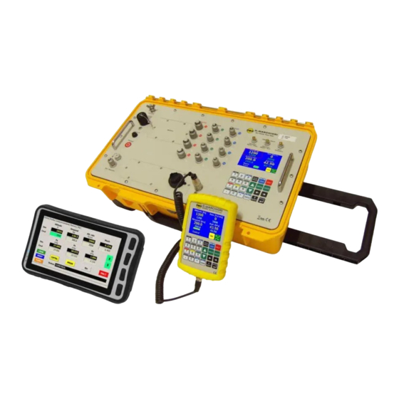
MPS49
AIR DATA TEST SET
OPERATING
MANUAL
D. MARCHIORI S.R.L.
Address: via Pontina km. 43.856 - 04011 Aprilia (LT) Italy
tel: +39-06-928 2733 – fax: +39-06-927 5401
e-mail: d.marchiori@dma-aero.com Internet: http://www.dma-aero.com
This Document is the property of D. Marchiori s.r.l., and may not be copied or otherwise reproduced,
communicated in any way to third parties nor stored in any data processing system without the
express written authority of D. Marchiori s.r.l.
1
D.Marchiori Copyright
Advertisement
Table of Contents

Summary of Contents for DMA MPS49
- Page 1 Address: via Pontina km. 43.856 - 04011 Aprilia (LT) Italy tel: +39-06-928 2733 – fax: +39-06-927 5401 e-mail: d.marchiori@dma-aero.com Internet: http://www.dma-aero.com This Document is the property of D. Marchiori s.r.l., and may not be copied or otherwise reproduced, communicated in any way to third parties nor stored in any data processing system without the express written authority of D.
-
Page 2: Table Of Contents
1.9 GETTING STARTED..........................7 1.9.1 INTERNAL BATTERY........................7 1.9.2 BATTERY CHARGING........................7 1.9.3 INTERNAL LEAK TEST......................... 8 1.9.4 DMA ADAPTOR KIT USE......................8 1.9.5 STATIC & PITOT PORTS SEALS....................8 1.9.6 VACUUM AND OVERPRESSURE GENERATION...............8 1.9.7 28V DC SUPPLY........................... 8 1.9.8 FIELD ALTITUDE.......................... - Page 3 CM170407AMA 4.4.2 VALUE MENUS........................... 22 4.5 SELECTING MEASURE UNITS......................23 4.6 AOA DISPLAY............................ 24 SECTION 5 START UP PROCEDURE......................25 SECTION 6 ENTERING AIR DATA TEST PARAMETERS................26 6.1 ENTERING SPECIFIC COMMANDED VALUES................26 6.2 MACH NUMBER AND AIRSPEED/QC LIMITS..................26 6.3 ACOUSTIC ALARM FUNCTION......................27 SECTION 7 ADVANCED OPERATIONS.......................
- Page 4 CM170407AMA 11.3 RUNNING TEST PROFILES......................44 11.4 PROFILE RESULTS.......................... 45 11.5 EXAMPLE............................46 SECTION 12 REMOTE CONTROL........................ 48 12.1 WIRED CONNECTIONS........................48 12.1.1 ETHERNET..........................48 12.1.2 GPIB............................48 12.2 WIRELESS CONNECTIONS......................48 12.2.1 BLUETOOTH..........................48 12.2.2 WI-FI............................49 SECTION 13 SPECIAL FUNCTIONS KEYS SUMARY.................50 SECTION 14 CALIBRATION.........................
- Page 5 CM170407AMA FIGURES FIG 1 MPS49 FRONT PANEL........................14 FIG 2 KEYBOARD LAYOUT.......................... 14 FIG 3 MPSRC REMOTE CONTROL......................15 FIG 4 KEYBOARD EXPLANATION....................... 16 FIG 5 THE STATUS SCREEN (AERONAUTICAL UNITS)................18 FIG 6 OPERATIONAL MODE INDICATION, WITH AND WITHOUT AOA LABEL........21 FIG 7 LEAK SCREEN IN AERONAUTICAL UNITS AND AOA SET TO ZERO..........22...
-
Page 6: Section 1 Preliminary
1.1 SAFETY The MPS49 is designed to be safe when operated in the manner described in this manual, it should be used only in the described way and for no other purposes. The manual contains Safety Instructions that must be followed, the instructions are either warnings or cautions given to protect the Operator and the equipment from damage. -
Page 7: Maintenance And Repair
(if available on the case) to prevent damage, to keep the pressure inside and outside of the case equal. • It is recommended to mount the MPS49 at a height of 1 meter above floor level where fuel vapor could be present, for example during re-fueling operations. •... -
Page 8: Internal Leak Test
Other cables could damage the instrument. 1.9.8 FIELD ALTITUDE The pressure control system of the MPS49 needs to know the altitude at which the unit is operated. On dispatch from Production the Qfe is set to a value of 260 feet. -
Page 9: Section 2 General Information
(Pd2), for testing Angle of Attack (AoA) smart probes. All rate values are also controlled. The MPS49 instrument is simple and fast to use. The operator interface is easy to understand by both experts and first time users. All testing and troubleshooting with the MPS49 is carried out via the touch-screen and an intuitively arranged color-coded keyboard on the front panel (FIG 2). -
Page 10: Range, Accuracy
CM170407AMA Simultaneous generation of altitude, airspeed and AoA. • Simultaneous generation of altitude and airspeed, allowing the AoA ports to be used as • additional static ports. Generation of altitude rate (climb or dive) (feet/min). • Generation of airspeed rate (increasing or decreasing) (knots/min). •... -
Page 11: Power
5V line (pin 5): 500 mA. • 2.2.4 PRESSURE MEDIA 2.2.5 MEASURE UNITS The operator can change the default units as required. Upon request, DMA can deliver the ADTS with different default units. Default Units are: feet, knots, hPa. •... -
Page 12: Physical Specifications
MPS49. Using a transfer calibration standard (for example the DMA's own PAMB11H), the MPS49 can be calibrated in typically less than 40 minutes. Please refer to the MPS49 Calibration and Adjustment Manual for more information. -
Page 13: External Supply Ports
2.2.12 EXTERNAL SUPPLY PORTS The MPS49 vacuum source is connected to a pneumatic port on the front panel. The port supports the use of DMA adaptor kits with suction cups. 2.2.13 OPTIONAL MULTIPLE ISOLATOR FUNCTION The MPS49 can be provided with up to four Ps, four Pt and four AoA connections. -
Page 14: Fig 1 Mps49 Front Panel
CM170407AMA FIG 1 MPS49 FRONT PANEL 1. Electrical ground connector 10. Static line outputs 2. External power socket 11. AoA line outputs 3. AC power LED 12. Pitot line outputs 4. Fuse 13. Additional communication ports 5. Power button 14. RS232 port 6. -
Page 15: Fig 3 Mpsrc Remote Control
CM170407AMA FIG 3 MPSRC REMOTE CONTROL D.Marchiori Copyright... -
Page 16: Section 3 Control Keys And Touch Screen
MEAS: sets the MPS49 into MEASURE mode. The pressure control system is turned off, leaving only the pressure measuring system active. This function is used to achieve extra accuracy, because it avoids any controller-induced effects on the measured pressures. - Page 17 SHIFT key is active. ENTER key is used to input desired data the MPS49. The operation is the same as the “Enter” key on a computer keyboard. BACKSPACE: is used to delete the last entered digit for correcting mistakes. LEAK: is used to automatically perform a leak test using the built in timer/stopwatch function of the MPS49.
-
Page 18: Section 4 Controlled Units, Operational Modes, Menus And Screens
Menus are screens that contain a list of parameters and allow their values to change. • 4.1 CONTROLLING AND DISPLAYING AERONAUTICAL OR PRESSURE UNITS The MPS49 can display and control either Aeronautical Units (Au) (altitude and airspeed) or Engineering Units, (Eu) pressures (static and dynamic). For rate control: When controlling aeronautical units, the altitude and airspeed rates are controlled. -
Page 19: Operational Modes
4.2 OPERATIONAL MODES 4.2.1 CONTROL MODE This is the primary mode for control of the MPS49. Air data parameter entry and all the operational/control functions are all performed in this mode. The main display used in this mode is the status screen (FIG 5). -
Page 20: Vent And "Ambient Pressure Reached" Modes
CONTROL mode if any problems are detected. 4.2.3 VENT AND “AMBIENT PRESSURE REACHED” MODES The Vent mode is used to vent the pitot and static ports of the MPS49 to the ambient pressure condition. The “Ambient Reached” mode is the operation mode that follows a successful venting procedure. -
Page 21: Leak Screen
FIG 6 OPERATIONAL MODE INDICATION, WITH AND WITHOUT AOA LABEL 4.3.2 LEAK SCREEN The Leak Screen (FIG 7) is shown when the MPS49 is in LEAK mode. It displays: the measured leaks (in the left part of the screen); •... -
Page 22: Menus
• value menus, displaying a set of values that may also be changed. • All MPS49 functions can be accessed from the Main Menu and its sub-menus Most MPS49 settings can be accessed through the Settings Menus. 4.4.1 CHOICE MENUS... -
Page 23: Selecting Measure Units
The “Back” button always exits the menu. 4.5 SELECTING MEASURE UNITS The MPS49 can display both simulated and commanded values in several measure units. The measure units can be changed from any screen featuring the yellow Unit button (e.g. the Status Screen). When the Unit button is pressed, a choice menu will appear, displaying all the measure units for the selected quantity. -
Page 24: Aoa Display
To permanently store new measure units as default in the MPS49 non-volatile memory, use the same procedures for permanent storage of new limits, as described in paragraph 8.2. -
Page 25: Section 5 Start Up Procedure
Turn the power toggle switch to “ON”. • The MPS49 display will first show a DMA logo; followed by the serial number of the unit • and last calibration date. -
Page 26: Section 6 Entering Air Data Test Parameters
1) by operating the MPS49 in the CONTROL mode. When the CONTROL mode is active, the MPS49 starts to change the pressures as soon as a new air data value is entered. 2) by operating the MPS49 in MEASURE mode. If it is desired that the MPS49 starts to... -
Page 27: Acoustic Alarm Function
6.3 ACOUSTIC ALARM FUNCTION When the simulated (actual) values are almost at the commanded (target) values, an acoustic alarm will start sounding (beep-beep) to warn the operator that the MPS49 is approaching the target values. The acoustic alarm function can be enabled or disabled from the Settings Menu, or by... -
Page 28: Section 7 Advanced Operations
7.2 LEAK TEST The MPS49 can perform a leak test of the static, pitot and AoA lines using a built-in timing function. Leak rates for pitot and static lines are calculated every second and are automatically shown in the selected units in the Leak Screen. -
Page 29: Fully Automatic Leak Tests
FIG 11 LEAK TEST RESULTS SCREEN 7.2.3 FULLY AUTOMATIC LEAK TESTS Fully automatic leak tests are a powerful feature of the MPS49: they allow the Operator to test complex pneumatic systems, at various altitude/airspeed values, taking advantage of the Multiple Isolator function (chapter 10.9) where available, to achieve a detailed overview of the pneumatic circuit. -
Page 30: Automatic Return To Ambient Pressure
4. Touch the yellow button Select. 5. Wait for the test to be completed. 7.3 AUTOMATIC RETURN TO AMBIENT PRESSURE MPS49 can automatically vent the static, pitot and AoA ports to the ambient pressure condition. The venting procedure operates as follows: when the VENT key (i.e. -
Page 31: Precision Measurements
The suggested procedure to follow in these cases is the following: 1. set the commanded values and wait for the MPS49 to reach them; 2. remain in CONTROL mode for some minutes, to allow the MPS49 to “actively” stabilize thermal effects and other transients;... -
Page 32: Encoding Altimeter (Option)
Operator may enable the “Ultra-low speed function” to enhance the resolution at • very low airspeeds. NOTE the AoA auto-zero may be disabled from the Settings Menu. Refer to the MPS49 Calibration and Adjustments Manual for more information. The ultra-low speed function can be enabled by entering the Main Menu (SHIFT + 3) and selecting “Functions”... -
Page 33: Arinc 429 Connection (Option)
Skip error: when the encoding altimeter skips one or more values (for instance, • switching from 1,000 to 1,200 feet). This error is marked as “Skip”. 7.6 ARINC 429 CONNECTION (OPTION) The optional ARINC 429 connectors on the front panel allow the MPS49 to receive data D.Marchiori Copyright... -
Page 34: Configuration
CM170407AMA from other instruments. 7.6.1 CONFIGURATION The ARINC 429 interface can be configured in “high speed” or “low speed” mode. The option is in the Settings Menu. Refer to the Calibration and Adjustment manual for more information. 7.6.2 DISPLAYING DATA COMING FROM THE ARINC 429 BUS The function can be enabled by entering the Main Menu (SHIFT + 3) and selecting... -
Page 35: Section 8 Changing Preset Limits
Limiting values can be changed for the duration of one power-on cycle, or stored permanently, in order to be recalled in the future. The MPS49 allows to store different sets of limiting values. The operator should consider carefully which requirement best suites the needs of all test set users and units under test. -
Page 36: Section 9 Safety Manual Operation
CM170407AMA SECTION 9 SAFETY MANUAL OPERATION 9.1 MANUAL VENT In the event of power loss and failure of the battery, the Ps, Pt and AoA lines can be returned to ambient pressure by means of manual valves. The three needle valves (FIG 1 items 15.), located on the front panel, are used for the manual venting. -
Page 37: Section 10 Special Functions
10.3 BATTERY LEVEL The Status Screen always displays the battery level. NOTE: while the MPS49 is connected to the AC power, the battery level will always be shown as 100%. To obtain an accurate reading, keep the power cable disconnected for one minute, with the ADTS in MEASURE mode. -
Page 38: Valves Fine Tuning (Map)
ONLY by skilled operators. 10.6 FINE TUNING FUNCTION The "Fine Tuning" function is only provided for skilled operators, to fine tune the MPS49 by the adjustment of the defined stored internal parameters; it is therefore restricted to SERVICE operators, see the MPS49 Calibration and Adjustments Manual. This function is not described in this manual. -
Page 39: Multiple Isolator Function (Option)
CM170407AMA Open the Main Menu (SHIFT + 3) and select “Functions” and “EPR”. The EPR Menu will show, allowing the operator to enter the desired values of the Static Pressure (inlet) and the target EPR value. Press the yellow button Go when ready. The Status Screen will show the EPR instead of the airspeed / Qc rate (FIG 18). -
Page 40: Special" Multiple Isolator Function
After closing (isolating) a port, press the MEAS key; the display will be as in FIG 20. The MPS49 switches into MEASURE mode and the buttons in the upper part of the screen disappear. Enter the new commanded values and press CNTR to enter CONTROL mode. -
Page 41: Altitude And Airspeed Oscillation (Option)
Period: the period of the oscillation, expressed in seconds. • Touch the green button Go to activate the function. The MPS49 will go through an initial preparation stage, and then will start oscillating. NOTE: the maximum amplitude and frequency of the oscillations are limited by the volume and geometry of the pneumatic load. -
Page 42: Section 11 Test Profiles
11.1.1 PROFILES AND PROFILE RESULTS A test profile contains a sequence of test points, that the MPS49 follows when the profile is run. Each test point contains the following data: altitude/Ps;... -
Page 43: Memory Organization
A test profile can be changed or created by touching the “Edit” button on the Profiles Menu. The MPS49 will show the Profile Selection Menu for selecting the memory location. If the Operator selects an empty memory location, a new profile will be created. -
Page 44: Running Test Profiles
If the profile requires an altitude offset, the Operator will be asked to confirm it. While a test profile is running, the MPS49 will show a slightly modified Status Screen (FIG 25); the lower-right part of the display summarizes the current state of the profile. -
Page 45: Profile Results
60 seconds. The Operator may dismiss the results' display before the timeout is expired. 4. the results of the step are stored into the active profile results. The MPS49 switches to the next profile step. After the last profile step is executed, the MPS49 switches back to the Status Screen. -
Page 46: Example
CM170407AMA FIG 26 THE PROFILE RESULTS SCREEN 11.5 EXAMPLE This chapter explains how to create an example test profile, with the following data: Step no. Altitude Alt. rate Airspeed Airsp. rate [ft] [ft/min] [kts] [kts/min] -1,000 ± 50 3,000 150 ± 5 0 ±... - Page 47 CM170407AMA g) Airsp. low.tol: -5; h) Airsp. rate: 300; Stab. time: 90; Leak test: Off 8. Press the orange button Back. 9. Select step 2 and touch the yellow button Edit. 10. Touch the yellow button Copy and confirm. The values from step 1 will be copied into step 2.
-
Page 48: Section 12 Remote Control
12.1 WIRED CONNECTIONS The MPS49, in standard configuration, is fitted with a RS232 port. A USB port is available as option. DMA provide a RS232 cable, and also a USB-RS232 cable, for systems that do not feature a RS232 port. -
Page 49: Wi-Fi
12.2.2 WI-FI A Wi-Fi dongle allows the MPS49 to be controlled over a TCP/IP connection on a Wireless LAN. 1. Connect the Wi-Fi adapter, wait for 5 seconds and select Wi-Fi REMOTE mode. -
Page 50: Section 13 Special Functions Keys Sumary
CM170407AMA SECTION 13 SPECIAL FUNCTIONS KEYS SUMARY Remember; press SHIFT followed by... SHIFT LEAK Vent to ambient pressure SHIFT Display Brightness Setting SHIFT Audible Beep/beep ON/OFF Setting SHIFT Enter the Main Menu SHIFT Enter the Remote Mode SHIFT Shorthand for the Tas / Ias menu SHIFT Same as touching the orange square button, if displayed SHIFT... -
Page 51: Section 14 Calibration
ISO17025 accredited laboratory with a Best Measurement Uncertainty no greater than ± 0.01% of reading over the entire MPS49 sensor ranges. Full details for carrying out the calibration of the MPS49 are to be found in the MPS49 Calibration and Adjustments Manual. -
Page 52: Section 15 Encoding Altimeter Connector Detail
SECTION 15 ENCODING ALTIMETER CONNECTOR DETAIL The following diagram enumerates the pin connections for the Encoding Altimeter interface plug / socket located on the front panel of the MPS49 (option H0). FIG 27 WIRE DIAGRAM OF THE ENCODING ALTIMETER CONNECTOR... -
Page 53: Section 16 Maintenance, Return And Disposal Information
CM170407AMA SECTION 16 MAINTENANCE, RETURN AND DISPOSAL INFORMATION The MPS49 contains complex electrical and electronic parts. It must disposed of properly. Please do not dispose of this equipment in landfill, with household or municipal waste. Due to the fact that all products are for specifically professional use, D.Marchiori s.r.l.
Need help?
Do you have a question about the MPS49 and is the answer not in the manual?
Questions and answers