Table of Contents
Advertisement
Quick Links
Advertisement
Table of Contents

Related Manuals for AUSTIN POWDER Shock Star

Summary of Contents for AUSTIN POWDER Shock Star
- Page 1 NON-ELECTRIC INITIATION SYSTEM USER‘S GUIDE CZECH REPUBLIC December 2019...
-
Page 2: Table Of Contents
CONTENT INTRODUCTION ..........................3 1 COMPONENTS OF NON-ELECTRIC INITIATION SYSTEM AND THEIR FUNCTION ....4 Shock*Star Surface ........................4 Shock*Star Bunch ........................4 Shock*Star Dual Delay ........................4 2 OPERATION PRINCIPLE OF A NON-ELECTRIC SYSTEM ............5 3 CONSTRUCTION AND TECHNICAL DESCRIPTION OF NON-ELECTRIC DETONATORS..6 IN-HOLE DETONATORS .................... -
Page 3: Introduction
INTRODUCTION SHOCK*STAR NON-ELECTRIC INITIATION SYSTEM DESIGNED AUSTIN DETONATOR S.R.O., CZECH REPUBLIC. THIS INITIATION SYSTEM INCREASES SAFETY AND ENSURES BETTER BLASTING RESULTS. THE SYSTEM WAS INTRODUCED TO THE MARKET IN 1993 AND SINCE THEN HAS SEEN THREE MAJOR MODIFICATIONS TO THE Surface CONNECTOR WHICH BROUGHT FURTHER RELIABILITY, PRECISION, AND SAFETY TO BLASTING IN FIELD. -
Page 4: Components Of Non-Electric Initiation System And Their Function
COMPONENTS OF NON-ELECTRIC INITIATION SYSTEM AND THEIR FUNCTION Austin Shock Tube and all Austin Detonator products using Austin Shock Tube can be initiated by regular electric, electronic or non-electric detonator, detonating cord, plain detonator, Shock*Star Bunch, Shock*Star Surface, proper blasting machine (from an open end of the Shock Tube only) and Rock*Star Starter. -
Page 5: Operation Principle Of A Non-Electric System
OPERATION PRINCIPLE OF A NON-ELECTRIC SYSTEM The basic principle of initiation in blasting pattern is transferring initiation from Surface Connector to a detonator in a hole and to another surface connector. The figure 2-1 shows properly timed blasting pattern - the holes are initiated well before the rock starts moving. -
Page 6: Construction And Technical Description Of Non-Electric Detonators
CONSTRUCTION AND TECHNICAL DESCRIPTION OF NON-ELECTRIC DETONATORS IN-HOLE DETONATORS Shock*Star MS (with 25 or 50 ms delay interval) Shock*Star TS (with 50, 100, 200 and 500 ms delay interval) These detonators have base charge of 720 mg. The detonators are made of aluminum shell containing the primary T-connector charge, delay composition system, Shock... - Page 7 IN-HOLE DETONATORS DELAY TIMES Shock*Star MS Shock*Star TS Delay Nominal delay Delay interval Delay Nominal delay Delay interval number time (ms) (ms) number time (ms) (ms) 0000 0025 0025 0100 0050 0150 0075 0200 0100 0250 0125 0300 0150 0350 0175 0400 0200...
-
Page 8: Shock*Star Surface
Shock*Star Surface Stopper The Shock*Star Surface is a highly user- friendly product bringing substantial time- savings when connecting initiation network. Traceability design connector virtually eliminates the shrapnel cut-off concerns, and makes easier the composition of initiation network. The connector has 9 delays. Base charge of Shock*Star Surface detonators is 120 mg. -
Page 9: Shock*Star Bunch
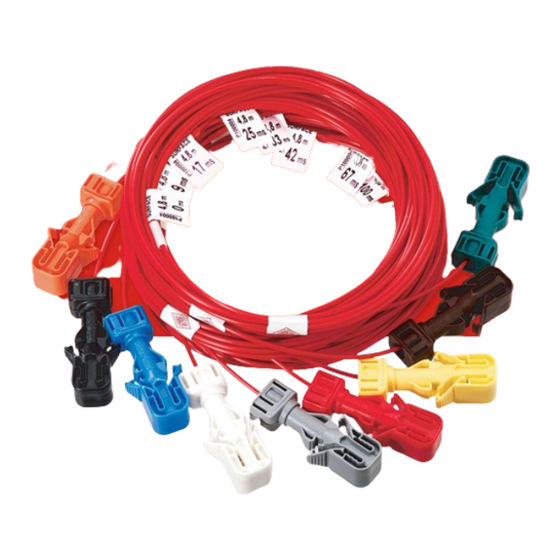
Shock*Star Bunch This detonator is fitted with a Bunch Connector with a 5 g/m PETN detonating cord. The detonator base charge of 160 mg is designed to initiate the attached detonating cord. Shock*Star Bunch is available in the following delays: 0, 9, 17, 25, 33, 42, 67, 100, 200 ms. -
Page 10: Bench Blast Design Using Shock*Star Dual Delay, Shock*Star Ms And Shock*Star Surface
Use of Shock*Star Dual Delay detonators brings the following advantage: reduced handling and storage requirements faster composition of initiation network reduced number of connections between units easier and more reliable visual inspection of connection TECHNICAL DATA Shock Tube Color: yellow... -
Page 11: Shock*Star Dc Relay
Shock*Star DC Relay Shock*Star DC Relay detonators are designed to provide accurate delay timing between the individual rows of blast holes using detonating cord as a primary initiation system. They can be used for developing various delay patterns. DC Relay consists of a 45 cm Shock Tube, two detonators plastic blocks. -
Page 12: Practical Use Of Non-Electric Detonators And The Benefits Of Use
PRACTICAL USE OF NON-ELECTRIC DETONATORS AND THE BENEFITS OF USE Shock*Star detonators are used for initiation of WARNING commercial explosives used for blasting both Non-electric detonators Shock*Star surface and underground. must not be used in underground Condition of use: worksites with a risk of ignition of coal ... -
Page 13: Use Of Shock*Star Ms Detonators In Surface Application
Use double loops for longer primers (≥700 mm). (Fig. 4-7) Fig. 4-7 USE of Shock*Star MS DETONATORS IN SURFACE APPLICATION The explosive in the blast hole is usually initiated in-hole detonators Shock*Star MS. One detonator is located at the bottom (lower) part of the drill hole. The other detonator is positioned at the top (upper) part of the drill hole, under the stemming. -
Page 14: Instruction For Use Of Shock*Star Surface
NOTICE ON THE SAFETY OF SHOCK TUBE Snap & Shoot Effect In the history of use of the non-electric (Shock Tube) initiation system, there occurred several instances of accidental tube initiation when the tube was pulled till its breakage. The instances were recorded during tubing production, detonator manufacture and also charging operations in the field. - Page 15 Fig. 4-10 Locking the tubes into connector CAUTION During connection make sure that the tubes are properly inserted into the connector block and that they are not crossed inside the connector block. Each side of the connector block can hold up to 4 tubes; the total capacity of the block is 8 tubes.
- Page 16 CAUTION Connect, place the connector at the distance at least 60 cm from the next connector or in-hole detonator. (Fig. 4-13, 4-14) Fig. 4-13 Fig. 4-14 DISCONNECTING Hold the loop as when connecting and pull the tube out from the connector block. Fig.
-
Page 17: Added Delay Created By The Shock Tube
ADDED DELAY CREATED BY THE Shock Tube As described Austin Shock Tube has velocity of detonation 2,000 m/s. This speed creates delay of 1 ms per every 2 m of Shock Tube. From this reason it is necessary to count with added delay by the Shock Tube and its variation based on place where connection to the Shock*Star Surface connector is been made. -
Page 18: Instruction For Use Of T-Connector ("J" Hook)
INSTRUCTION FOR USE OF T-CONNECTOR (“J” HOOK) Steps to follow to make proper CONNECTION Fig. 4-18 Correct way to connect Shock*Star detonators equipped by T-connector (“J” hook) to detonating cord NOTICE Make sure that the detonating cord is straight in the T-connector (“J”... -
Page 19: Instruction For Use Of Shock*Star Dc Relay
INSTRUCTION FOR USE OF Shock*Star DC Relay Steps to follow to make proper CONNECTION Fig. 4-20 Correct way to connect Shock*Star DC Relay NOTICE For easy connection it is important to have a clean cut of the detonating cord. Place the cord on a wooden plate and cut the cord at right angles using a sharp knife. -
Page 20: Coupled Initiation Blasting Pattern
Fig. 4-21 Austin Detonator, on the other hand, recommends designing the blasting pattern in such a way, that if in one element, the initiation is stopped, entire initiation process is stopped and only properly initiated holes blast. This method is shown in figure 4-22 and is considered by blasters as an important preventive measure which could be taken to avoid problems with removing misfires. -
Page 21: The Bench Blasting Examples
4.7.3 The bench blasting examples Three-row one-side-initiated bench blast All blast holes are charged with detonators of identical nominal delay time. Shock*Star Surface provides individual blast hole timing. The delay between holes in the rows is 17 ms, the delay between rows is 67 ms and 100 ms. - Page 22 Floor height leveling in one shot with bench blast Fig. 4-26 shows ideal approach toward connection of a hump blasting together with production bench blast. The approach should be that the small blast goes before the production blast and that the production blast is connected to the hump.
-
Page 23: Using Shock*Star In Underground Applications
USING Shock*Star IN UNDERGROUND APPLICATIONS The advantage brought by non-electric initiation system Shock*Star can be conveniently used for tunneling and underground blasting as well. Shock*Star TS has been especially designed for these applications. Normally, the detonator is inserted into a booster or an explosive charge to form a primer for the hole. -
Page 24: Detonating Cord End Connection
Ensure that remaining length of the detonating cord is not close to the Shock Tubes, see figure 4- 31, and that the end of detonating cord is fixed either to Shock Tube of Shock*Star Bunch or to Shock Tube oand distance between detonating cord and any in-hole detonator Shock Tube is 30 Fig. -
Page 25: Always And Nevers When Using Shock*Star Bunch
Fig. 4-33 4.8.3 Always and Nevers when using Shock*Star Bunch NEVER Use 5 g/m PETN detonating cord Use more than 20 tubes in bunch. ALWAYS for creating bunches. ALWAYS Have a minimum of 5 tubes in a NEVER Allow the free end of the DC in close bunch. -
Page 26: Connecting Of Two Shock Tubes Together
reliable connection to detonating cord for initiation of detonators. The detonating cord itself is then initiated by any detonator. One of the advantages of using detonating cord/T-connector combination is easy and fast connecting resulting in increased safety of the whole blast work. 4.10 CONNECTING OF TWO Shock Tubes TOGETHER Austin Shock Tubes are possible to connect with a plastic connecting tube supplied together with... - Page 27 2. Initiation by means blasting machine Fig. 4-37 MICKO - 1, blasting machine for initiation of electric and non-electric detonators Fig. 4-38 Mechanical blasting machines HR-22 and Mushroom stomper starter which are using #209 primers 3. Initiation by means of a non-electric detonator Non-electric detonator with long Shock Tube supplied on spool is the best way for firing the blast.
-
Page 28: Instruction How To Assemble Rock*Star Starter Detonator
Fig. 4-40 Correct and Incorrect way how to initiate Shock Tube reeled on spool. 4. Initiation by Rock*Star Starter detonator Electric detonator Rock*Star Starter consists of electric detonator Rock*Star 25/50 and Shock*Star Surface connector block. It is designed to initiate Shock Tube or 5 gram detonating cord. - Page 29 Fig. 4-43 Close the connector block Fig. 4-44 Check that the lock is correctly closed Fig. 4-45 Connecting point Shock Tubes or the detonating cord to the connector must be at least 10 cm from the Shock Tube or detonating cord end. Connect the Shock Tubes based on description in chapter 4.3 of this user’s guide.
-
Page 30: Always And Nevers When Using Rock*Star Starter
Initiation of Rock*Star Starter will cause shrapnel effect. It is necessary to cover the connector by inert material (gravel, soil, sand). 4.11.2 Always and Nevers when using Rock*Star Starter NEVER use standard Shock*Star Surface use electric detonator #3 (75 ms). ALWAYS for initiation of detonating cord. -
Page 31: Package, Storage And Shelf Life
PACKAGE, STORAGE AND SHELF LIFE PACKAGING Assembled non-electric detonators are packed into cardboard cartons. Inside the cartons the detonators are packed in vacuum-sealed plastic bags. The quantity per carton is determined by the Shock Tube length (see product information brochures for each separate product). The cartons are tested and certified and are in strict conformity with the International Agreement of Road, Train, Sea and Air Transport (ADR, RID, IMDG, IATA). -
Page 32: Shelf Life And Storage Conditions
SHELF LIFE AND STORAGE CONDITIONS a) For non-electric detonators packed in original unopened aluminum foil bags, the shelf life is 2 years, if stored in temperatures between -30 and +40°C. After opening the foil bag, it is recommended to use the detonators within 3 months. For non-electric detonators packed in original unopened plastic bags, the shelf life is 2 years if stored in temperatures between -30 and +40°C and relative humidity not exceeding 65%.
Need help?
Do you have a question about the Shock Star and is the answer not in the manual?
Questions and answers