Table of Contents
Advertisement
Quick Links
MoTeC
Contents
Introduction ........................................................................ 1
Overview ............................................................................. 2
Display ................................................................................................................ 2
Alarms ................................................................................................................. 5
Data Logging ...................................................................................................... 5
Other Functions .................................................................................................. 7
Measurement Inputs ........................................................................................... 8
Auxiliary Outputs ............................................................................................... 12
Communications Overview ............................................................................... 13
ECU Connection ............................................................................................... 13
Lap Beacon ....................................................................................................... 14
Options ............................................................................................................. 14
Software ............................................................................................................ 14
Updateable Firmware ........................................................................................ 15
Installation ........................................................................ 17
Mounting ........................................................................................................... 17
Display Care ..................................................................................................... 18
Wiring ................................................................................................................ 18
External Buttons ............................................................................................... 19
External Lights .................................................................................................. 20
Thermocouples ................................................................................................. 20
Connecting to a Mo T eC ECU ............................................................................. 20
Sport Dash Manager Software ........................................ 23
Introduction ....................................................................................................... 23
Computer Requirements ................................................................................... 23
Installing Sport Dash Manager .......................................................................... 24
Mouse & Keyboard ........................................................................................... 24
Main Menu ........................................................................................................ 24
Toolbar .............................................................................................................. 25
On line / Off line ................................................................................................ 25
Configuration .................................................................................................... 26
Configuration Files ............................................................................................ 26
Changing the Configuration .............................................................................. 27
Versions and Updating ...................................................................................... 28
Channels ........................................................................................................... 29
Conditions Overview ......................................................................................... 33
Checking Operation .......................................................................................... 34
Sensor Zeroing ................................................................................................. 35
Details Editor .................................................................................................... 35
SDL User Manual
Advertisement
Table of Contents

Related Manuals for Motec SDL


Summary of Contents for Motec SDL
-
Page 1: Table Of Contents
MoTeC SDL User Manual Contents Introduction ................ 1 Overview ................2 Display ........................ 2 Alarms ......................... 5 Data Logging ...................... 5 Other Functions ....................7 Measurement Inputs ................... 8 Auxiliary Outputs ....................12 ... - Page 2 Appendix E: Auxiliary Output Characteristics ............ 52 Appendix F: CAN Bus Specification ..............53 Appendix G: ECU to SDL Wiring (RS232) ............54 Appendix H: CAN Wiring ................... 56 Appendix J: USB Wiring ..................57 ...
-
Page 3: Introduction
Introduction Thank you for purchasing a MoTeC SDL Dash / Logger. The MoTeC SDL Dash / Logger is a combined LCD dash unit and high performance data logger. Note that a ‘display only’ version of the SDL is also available This Manual Covers: •... -
Page 4: Overview
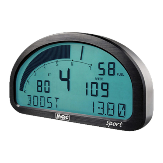
Overview Overview Display The SDL display is a high contrast, high temperature, custom made LCD display. The display contains a Bar Graph, three Numeric Displays, a Centre Numeric Display and a Bottom Alpha / Numeric Display. Bar Graph The 70 segment bar graph has a user definable range and is typically used as a tacho, however it can be used to display any other value. - Page 5 MoTeC Overview Numeric Displays The three numeric displays (Left, Right and Top Right) can be programmed to display any value. Note that each of the three numeric displays has a different number of digits and are therefore suited to displaying different values. For example the Top...
- Page 6 Overview The Centre Numeric display is incorporated to show the current gear but may be used for other purposes. Bottom Display The 13 digit alpha numeric display can display up to 10 lines of information that can be scrolled up or down using the external buttons. Each of the 10 lines can display up to 3 channel values at a time.
-
Page 7: Alarms
SDL for later analysis. Logging Memory The SDL comes with an optional 8Mbytes log memory enabled. It is also possible to purchase a ‘display only’ SDL without the memory option enabled. Data is logged continuously logs data to memory whenever the Start... - Page 8 Logging Rate The SDL can store any value at up to 200 times per second, which can be individually set for each logged item. The rate at which the values are logged is very important – the value must be logged fast enough to record all variations in the reading.
-
Page 9: Other Functions
Retrieving the Logged Data A laptop or desktop PC is used to unload the logged data from the SDL. The logged data is then stored on the computer hard disk. The logged data may be retrieved at very high speed (approximately 2.5 seconds per Mbyte when using USB or 20sec Mbyte when using CAN). -
Page 10: Measurement Inputs
This allows the SDL to measure vehicle parameters such as: Suspension Movement, Wheels Speeds, Steering Angle, Engine Temperature etc. Input Types The SDL has a number of different input types which are designed to suit the different types of sensors. The following inputs are available: •... - Page 11 Additionally one E888 expander may be connected to read from 8 K-type thermocouples. Internal Sensors The SDL also includes internal sensors for G-Force Lateral, G-Force Vertical, Battery Voltage and SDL Internal Temperature. Sensors Different types of sensors are available to suit different types of measurements.
- Page 12 • Two wire variable resistance pressure sensors Some voltage output sensors can also be used if they can drive the 1000 ohm resistor without causing an error in their reading (eg MoTeC Thermocouple Amplifier). Additionally, on/off switch signals may be connected.
- Page 13 Switch Inputs The 2 switch inputs are generally used for the external switches required to operate the SDL display. They can also be connected to a brake switch or other switch. These inputs have a 4700 ohm resistor connected internally from the input pin to the 5V sensor supply so that a switch can be simply connected between the input pin and 0 volts.
-
Page 14: Auxiliary Outputs
Expander Thermocouple Inputs An E888 expander may be connected to the SDL to read the 8 thermocouple inputs. These are added and calibrated when the CAN comms template “E8xx Rx EGT” is selected as one of the 6 possible CAN devices. -
Page 15: Communications Overview
This avoids duplication of sensors and allows the SDL to display and log many ECU parameters. The ECU may send up to 40 values to the SDL. The update rate of these values depends on how many values are transmitted, the communications baud rate and if sent using CAN or RS232. -
Page 16: Lap Beacon
Lap Beacon A Lap Beacon can be connected to the SDL in order to record Lap Times for display and to provide lap reference information for the data logging analysis software. -
Page 17: Updateable Firmware
SDL. An overview of Sport Dash Manager is included later in this manual. Sport Dash Manager communicates with the SDL via a USB cable. See Appendix J: USB Wiring for wiring details. -
Page 19: Installation
Attachment Use washers between the unit and the mounting panel to ensure that the unit is mounted only at the mounting points (to avoid twisting the case). The SDL has three threaded mounting posts. Do not over tighten the mounting screws (to avoid twisting the case). -
Page 20: Display Care
Ensure that the correct crimping tool is used for all contacts to ensure a reliable connection. The correct mil spec crimping tool must be used for the SDL crimp pins. See Appendix N: Connector for details. • Note that the Crimp Contacts are type 22D which is needed to set the... -
Page 21: External Buttons
Installation Power Wiring Power the SDL via a separate switch and a 5 Amp fuse. The separate switch is recommended so that the computer can communicate with the SDL without needing to turn the rest of the vehicle power on. -
Page 22: External Lights
The SLM includes 8 LEDs that can be programmed to any colour and can be used for both warning lights and multiple shift lights plus many other functions. The SLM is connected to the SDL via the CAN bus so it does not occupy any of the auxiliary outputs. LEDs LEDs may be wired to any of the four Auxiliary Outputs. - Page 23 The MoTeC M4, M48 & M8 ECUs must be connected via RS232. Connection via RS232 The telemetry feature of the MoTeC ECU is used to send data to the SDL via an RS232 connection. See Appendix G: ECU to SDL Wiring (RS232) for wiring details.
- Page 24 Installation SDL Setup Setup for the SDL is done in the ‘Inputs | Communications’ setup screen. Select a communications template that matches the ECU type and ECU set. In the displayed channel list, check those channels that you wish to receive in the SDL.
-
Page 25: Sport Dash Manager Software
The PC must have a USB1.0 or compatible USB port or a Printer port. The USB port is the recommended connection method because it is much faster however if necessary a MoTeC CAN Cable may be used instead which should be connected to the printer port. -
Page 26: Installing Sport Dash Manager
Software Updates then Current Release Software. Click on one of the SDL Sport Dash Manager link to start the down load and choose to save the file to a location where it can be easily located after downloading (such as the desktop). After downloading double click on the file to start the installation process. -
Page 27: Toolbar
All changes to the SDL configuration are performed ‘Off Line’, i.e. without the PC communicating with the SDL. Once the configuration changes have been made and saved to a file, they can be sent to the SDL which is an ‘On line’ process, i.e. the PC is communicating with the SDL. -
Page 28: Configuration
Configuration The configuration of the SDL determines exactly how it operates. The strength of the SDL lies in its flexibility of configuration. All aspects of the SDL can be configured including, which sensor is connected to which input, the calibration of each sensor, what to display and where to display it, what to log and how fast to log it, tacho range, warning alarms, multi stage shift lights, etc, etc. -
Page 29: Changing The Configuration
‘Save Backups’ directory. The total number of files is limited to 100. When a file is sent to the SDL the existing SDL data is retrieved and stored in the ‘From Dash Backups’ directory, this is in case the data in the SDL needs to be restored. -
Page 30: Versions And Updating
Versions and Updating Updating The software inside the SDL can be updated by the user at any time to take advantage of the latest features offered by MoTeC. To update the SDL software version select Online | Upgrade Dash Version from the Sport Dash Manager main menu. -
Page 31: Channels
Channels Channels are used to convey information between the various systems of the SDL. For example an input pin may feed a channel called ‘Engine Temperature’, this channel may then be used by any other system, such as the Display or Data Logging systems. - Page 32 Sport Dash Manager Software Channel List MoTeC has defined an extensive list of channels. All systems within the SDL that generate values must choose to feed into one of these channels. General Purpose Channels Since the use of all channels can not be predetermined, a number of general purpose channels have been included for occasions when a suitable predefined channel is not available.
- Page 33 MoTeC Sport Dash Manager Software • Suitable Display filtering • Minimum and Max Range Predefining these properties makes the channels easy to use throughout the rest of the software, for example knowing the measurement type allows the channels to be displayed in any units suitable for that type, with automatic conversion between the units.
- Page 34 Sport Dash Manager Software When selecting a channel from the complete list of channels, it is usually easiest to use the category selection method, for example when assigning a channel to an input pin. To expand a category click on the + sign next to the category name.
-
Page 35: Conditions Overview
MoTeC Sport Dash Manager Software Search Method This method lists all channels in alphabetical order and allows a channel to be found either by typing the first few letters of any word in the channel name, or by scrolling through the list. -
Page 36: Checking Operation
Utilities | Oscilloscope button on the Monitor Channels screen. Tests A number of tests are provided to check the operation of the SDL, such as the Analogue Input and Auxiliary Output Tests. The Auxiliary Output test is very useful for checking wiring and operation of shift lights for example. The Analogue Input test is very useful when checking sensor wiring. -
Page 37: Sensor Zeroing
MoTeC Sport Dash Manager Software Sensor Zeroing Some sensors require regular zeroing, for example Steering Angle, Suspension Position, Ride Heights, G Force Sensors & Throttle Position. Sport Dash Manager provides a screen to allow easy zeroing of all these sensors. -
Page 39: Windows Keyboard Use
MoTeC Windows Keyboard Use Windows Keyboard Use This section gives details on how to use the keyboard with Windows applications. Main Menu The Main Menu can be accessed by holding down the Alt key then pressing the key corresponding to the underlined letter in the menu name, followed by the underlined letter of the item in the drop down menu. -
Page 40: Selecting An Item In A Window
Windows Keyboard Use Selecting an Item in a Window To access the various items in a window hold down the Alt key and press the key corresponding to the underlined letter of the item of interest, for example to select the ‘Flash Light’ item press Alt F Alternatively the Tab key may be used to progress from one item to the next (use Shift Tab to move backwards). - Page 41 MoTeC Windows Keyboard Use Button Buttons are generally used to show another screen or perform a particular function. Hold down the Alt key then press the underlined Letter ( S ), or navigate to the button using the Tab key then press the Enter key or the Space Bar.
- Page 42 Windows Keyboard Use Drop down List A drop down list is used to select from a number of items, but only the selected item is shown until a new item needs to be selected. Hold down the Alt key then press the underlined Letter of the text above the list ( L ) or navigate to the button using the Tab key then select the desired item using the Arrow keys, Press the Enter key to close the list.
- Page 43 MoTeC Windows Keyboard Use...
-
Page 44: Appendices
Appendices Appendices Appendix A: General Specifications Physical Case Size SDL: 180.5 x 91.5 x 18.0 mm (7.1 x 3.6 x 0.7 inches) Weight 385 grams (0.85 lb) Power Supply Operating Voltage: 7 to 22 Volts DC Operating Current: 0.15 Amps Typical (excluding sensor currents) -
Page 45: Appendix B: Options Summary
MoTeC Appendices Appendix B: Options Summary The following options are available: Pro Analysis Option Advanced Analysis features in the Interpreter software, including: • multiple graph overlays • time variance between 2 laps • statistical zoom on sections of data •... -
Page 46: Appendix C: Sport Dash Manager Command Line
-c[connection] -d -x -l -e -t -s [config file name] [config file name] (Optional) Fully qualified path to the configuration file. (eg "c:\motec\dash\config\SDL\bathurst.u11") Note: the path must included the file extension (eg .u11) Options : Each of the following options can be given as "/[character]" or "-[character]". - Page 47 Perform a “Print Summary” operation. Note: The config file must be specified using a fully qualified path including the file extension. (eg -p "c:\motec\dash\config\SDL\bathurst.u11") Note: There must be a space between -p and config name. (Optional) Perform a “Send Configuration” operation.
-
Page 48: Appendix D: Input Characteristics
Appendices Appendix D: Input Characteristics Analog Voltage Inputs Suitable for: Potentiometers, Voltage output sensors & Variable resistance sensors with a pullup resistor Measurement Voltage Range: Inputs 1 to 4: 0 to 5.5 V Inputs 5 to 8: 0 to 15.3 V •... - Page 49 Temperature Stability 60 ppm/°C max Calibration Schedule 12 Months Lambda Input Type: Wide Band MoTeC Measurement Range: 0.75 to 1.50 Lambda (or 0 to 1V) Accuracy: 1.5 % up to 1.20 Lambda Update Rate: 100 times / second Switch Inputs...
- Page 50 Appendices Filter Time Constant: 22usec Digital Inputs Suitable for: Switch to 0V, Logic signal & open collector device (eg Hall Switch) Pullup Resistor: 4700 ohms to 5V Voltage Range: 0 to 15V Positive Trigger Threshold: 3.5 V max Negative Threshold: 1.0 V min Hysteresis: 0.5 V Min Update Rate: 100 times / second Filter Time Constant: 22usec...
- Page 51 MoTeC Appendices Maximum: 32 msec Pulse Width 100 usec Measures pulse low time Resolution: 100 usec Maximum: 3.2 sec Speed Inputs Can be used in two modes: Hall or Magnetic. In Hall mode a 4700 ohm pullup resistor is connected to 5V and the trigger levels are fixed.
- Page 52 Appendices Pulse Width 1 usec Measures pulse high time Resolution: 1 usec Maximum: 32 msec Pulse Width 100 usec Measures pulse high time Resolution: 100 usec Maximum: 3.2 sec Speed Input Modes HALL Mode Suitable for switch to 0V, Logic signal or open collector device (eg Hall Switch) Pullup Resistor: 4700 ohms to 5V Voltage Range: 0 to 15V...
- Page 53 MoTeC Appendices Sampling alternates between Group1 and Group2 and is scheduled every 1.000msec Group1 Group2 Internal SDL Temp Internal Battery Voltage Internal Ref/2 AD2 Internal Ref/2 AD3 Internal 0V AD2 AV10 Internal 0V AD3 Internal Abs Ref 4V5 Internal Ref AD2...
-
Page 54: Appendix E: Auxiliary Output Characteristics
Appendices Appendix E: Auxiliary Output Characteristics Output Type: Open Collector (Drives to ground) with weak pullup (10k ohms) to battery positive. Control is by On/Off condition only, the Auxiliary outputs do not support variable frequency or duty cycle control. Current: 0.5 Amp max, current limited & thermal overload protected Output Clamp: 50V Flyback Clamp (No Clamp Diode to supply). -
Page 55: Appendix F: Can Bus Specification
MoTeC Appendices Appendix F: CAN Bus Specification CAN Bus Data Rate: 1Mbit/sec Terminating impedance and data cable impedance: 100 ohms: dictated by the PC communications cable (CAN cable) Maximum length: 16 m (including the CAN Cable if present). -
Page 56: Appendix G: Ecu To Sdl Wiring (Rs232)
SDL via RS232. In all cases this is done using the serial data stream generated by the Telemetry function of each ECU. In the case of the M800, M880 and M4e the SDL may be directly wired to the ECU because these ECUs use RS232 interface levels. On the M48, M4 (pre M4e) and the M8 a Computer Interface Module (CIM) or a PCI cable is required to convert the signals to RS232. - Page 57 M4 / M48 / M8 PC Connector Refer to the CIM module drawing for full wiring details. Note that the data to the SDL will be interrupted while a PC is connected. Using a PCI Cable - Direct Connection PCI Cable...
-
Page 58: Appendix H: Can Wiring
OK. The maximum length of the bus is 16m (50ft) CAN Devices (such as MoTeC SDL, BR2 etc) may be connected to the trunk with up to 500mm (20in) of twisted wire. Note that the “CAN Cable Connector” is not normally used since the SDL uses USB for communications. -
Page 59: Appendix J: Usb Wiring
Appendices Appendix J: USB Wiring The USB connection should be made by wiring a USB cable to the SDL main connector as shown below: The USB cable should have a type B socket so that a standard USB A to B cable can be used to connect between it and the PC. -
Page 60: Appendix K: Typical Wiring (With Br2)
Appendices Appendix K: Typical Wiring (with BR2) The wiring below shows typical wiring for BR2 on CAN plus USB for PC connection. For more detail on the CAN Bus wiring refer to Appendix H: CAN Wiring. For more details on USB wiring refer to Appendix J: USB Wiring. USB B Type Socket... -
Page 61: Appendix L: Pin List By Function
MoTeC Appendices Appendix L: Pin List by Function Name Function Battery Power BAT- Battery Negative BAT+ Battery Positive Analog Volt Inputs Analog Voltage Input 1 Analog Voltage Input 2 Analog Voltage Input 3 Analog Voltage Input 4 Analog Voltage Input 5... - Page 62 Appendices Auxiliary Outputs AUX1 Auxiliary Output 1 AUX2 Auxiliary Output 2 AUX3 Auxiliary Output 3 AUX4 Auxiliary Output 8V Sensor Sensor 8V 5V Analog Sensor Sensor 5V Analog Volt & Analog Temp 0V Analog Sensor Sensor 0V Analog Volt & Analog Temp CAN Interface CAN-LO CAN-LO...
-
Page 63: Appendix M: Pin List By Pin Number
MoTeC Appendices Appendix M: Pin List by Pin Number Name Function Analog Voltage Input 5 Analog Voltage Input 6 BAT+ Battery Positive BAT- Battery Negative AUX1 Auxiliary Output 1 AUX2 Auxiliary Output 2 AUX3 Auxiliary Output 3 AUX4 Auxiliary Output 4... -
Page 64: Appendix N: Connector
Appendices Appendix N: Connector SDL Mating Connector 37 way Deutsch: AS6-14-35SN Wire Wire to suit connector: 22# Tefzel, Mil Spec : M22759/16-22 Crimp Tool Crimp Tool : M22520/2-01 Positioner for Crimp Tool : M22520/2-07 • Note that the Crimp Contacts are type 22D (needed to set the crimp tool... -
Page 65: Appendix P: Wire Specifications
MoTeC Appendices Appendix P: Wire Specifications M22759/16 Wire Ratings (For Various Wire Gauges) Insulation Material : Tefzel Conductor : Tin Plated Copper Voltage Rating : 600 V Maximum Temperature : 150 °C Wire Cross Max Current Resistance Resistance at 100 °C... -
Page 66: Appendix Q: Case Dimensions
Appendices Appendix Q: Case Dimensions... - Page 67 MoTeC Notes...
- Page 68 Notes...
- Page 69 MoTeC Notes...
- Page 70 Notes...
Need help?
Do you have a question about the SDL and is the answer not in the manual?
Questions and answers