Table of Contents
Advertisement
Quick Links
CAP
Description
Model
Complete
51300S
CAP System Kit
(for Carlin burners without covers)
Low Rate CAP Kit
51300AS
(for Carlin burners with covers)
Medium Rate CAP Kit
51300BS
(for Carlin burners with covers)
High Rate CAP Kit
51300CS
(for Carlin burners with covers)
Note: All CAP System models require Carlin 70200
Primary Control manufactured after Sept. 2018
Patent No. 11,428,407
©
Copyright 2022 – Carlin Combustion Technology
Firing Rate (GPH)
0.50 - 2.00
0.50 - 1.00
1.05 - 1.45
1.50 - 2.00
1
System Kit
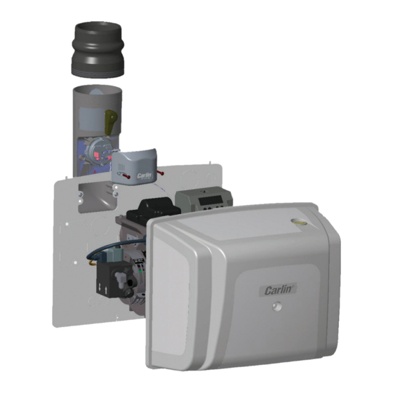
Combustion
Air Proving Kit with
Burner Cut-Off
Designed to meet NFPA31*
requirements for combustion air
Installation Instructions
and Operating Manual
Electrical shock hazard. To prevent electrical
shock, death, or equipment damage, disconnect power sup-
ply before installing or servicing CAP System. Only qualified
personnel may install or service the CAP System in accor-
dance with local codes and ordinances. Read instructions
completely before proceeding.
*See Section 5.4.3.3 as covered by April 2019 TIA 16-2
Carlin Combustion Technology
126 Bailey Road
Phone 203-680-9401
T
800-989-2275
ech support
CAP
North Haven, CT 06473
Fax 203-680-9403
carlincombustion.com
Advertisement
Table of Contents

Subscribe to Our Youtube Channel
Summary of Contents for Carlin 51300S
- Page 1 51300CS 1.50 - 2.00 (for Carlin burners with covers) *See Section 5.4.3.3 as covered by April 2019 TIA 16-2 Note: All CAP System models require Carlin 70200 Primary Control manufactured after Sept. 2018 Carlin Combustion Technology 126 Bailey Road North Haven, CT 06473 Patent No.
- Page 2 C A P S Y S T E M K I T C O M P O N E N T S ( s e e p a g e 3 f o r p a r t d e s c r i p t i o n s ) COMPONENTS CONTAINED IN POLYBAG...
- Page 3 C A P S Y S T E M K I T C O M P O N E N T S MODEL Reference Description Part Number Quantity Number 51300S 51300AS 51300BS 51300CS • Burner Cover 50404ABLK Following items come assembled with Burner Cover (above) •...
- Page 4 1.05-1.45 50806B 1.50-1.90 50806C Ensure that the burner is equipped with a Carlin Pro-X 70200 primary control with low voltage blocked vent (BV) terminals as shown. NOTE: 70200 controls • • Reroute any BX cable, wiring harness, etc. through one...
- Page 5 SEAL THE BACKPLATE • • Use the plastic rivets at the bottom corners of the • Install the 1.62"split grommet around any BX cable, filler plate to properly align the filler plate with the burner wiring harness, etc. leaving the burner backplate backplate •...
- Page 6 SEAL THE COVER Slide the connecting flange onto the air inlet until fit is tight. Reverse flange when using galvanized • Install the rubber filler into the 4" opening in the bot- piping. Secure with clamp tom of the cover as shown.
- Page 7 Use the NOTE: If the Pro-X 70200 is also connected to a table below to set the combustion settings based on blocked exhaust switch, call Carlin Technical Support outside temperatures at the time of setup. for assistance.
- Page 8 With the CAP System installed and the cover securely the firing rate of the burner – see table on page 2. Carlin’s mounted, initiate a call for heat and allow the burner to Complete CAP System Kit (51300S) contains all three pressure fire.
Need help?
Do you have a question about the 51300S and is the answer not in the manual?
Questions and answers