Table of Contents
Advertisement
Quick Links
This document contains information highly confidential to RoyalTek Company LTD (RoyalTek).
It is provided for the sole purpose of the business discussions between supplier and RoyalTek
and is covered under the terms of the applicable Non-Disclosure Agreements. Disclosure of
this information to other parties is prohibited without the written consent of RoyalTek.
RTM-6000 User Manual
Version 1.4
2009/04/14
Prepared by RoyalTek Company LTD.
4F, 188, Wen Hwa 2
Tao Yuan 33377, Taiwan
TEL: 886-3-3960001
FAX: 886-3-3960065
http://www.royaltek.com/contact
nd
Rd., Kuei Shan.
Advertisement
Table of Contents

Summary of Contents for RoyalTek RTM-6000
- Page 1 2009/04/14 This document contains information highly confidential to RoyalTek Company LTD (RoyalTek). It is provided for the sole purpose of the business discussions between supplier and RoyalTek and is covered under the terms of the applicable Non-Disclosure Agreements. Disclosure of this information to other parties is prohibited without the written consent of RoyalTek.
- Page 2 0. Revision Histories Release Date Change Description Editor 2007/08/29 Initial Draft Amanda Lee 2007/10/24 Increasing 8. temperature profile Amanda Lee 2008/05/23 Change schematic Linda Fan Change RDS sensitivity 2008/10/30 May Chen 2009/04/14 Add Product applications May Chen...
-
Page 3: Table Of Contents
Content Intruduction ....................... 4 Product Features ..................4 Product Applications..................4 System Block Diagram ................5 Specification......................6 Reference schematic:....................8 Hardware Interface: ....................9 Recommend layout PAD: ..................11 Layout Note:......................12 Mechanical Drawing ....................12 Temperature Profile ....................13... -
Page 4: Intruduction
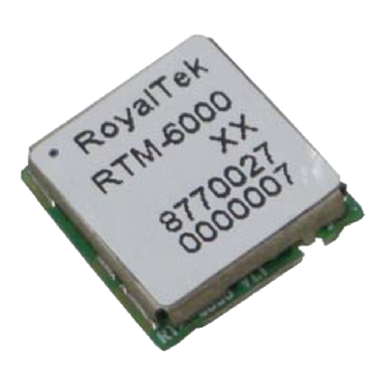
RoyalTek RTM-6000 is the RDS-TMC demodulator module using Silicon Lab Si4703 chip and Silicon Lab C8051F331 MCU. RTM-6000 has a low power consumption and can operate at a low supply voltage. The module demodulates the RDS-TMC in FM band from 87.5MHz to 108MHz. The block data and status information are available via I²C bus. -
Page 5: System Block Diagram
1.3 System Block Diagram System block diagram, FM_ANT OUTPUT AUDIO_R AUDIO_L C2DAT SCLK MICROCONTROLER C2CLK SDIO C8051F331-GM nINT Si4703 nRST1 INTERFACE CONTROLER RCLK V_IN_3V3 POWER... -
Page 6: Specification
2 Specification Function Specification Mechanical requirements Weight ≦0.43 g Dimension 10mm±0.2mm(L) x 9.3mm±0.2mm(W) x 2mm+0.25-0.10mm(H) TMC/RDS receiver Chipset Silicon Lab Si4703-GM Frequency 87.5~108MHz. US/Europe sensitivity 2.5 μVEMF typ. (S+N)/N=26dB FMOD = 1 kHz, 75 μs de-emphasis MONO = 1, and L = R unless noted otherwise. Δf = 22.5 kHz. - Page 7 unless noted otherwise. Δf = 22.5 kHz. BAF = 300 Hz to 15 kHz, A-weighted. VEMF = 1 mV, fRF = 87.5 to 108 MHz. Audio Stereo S/N Δf = 22.5 kHz. Environment Environment Building in Navigation Cube Operating temperature -20 °C to +85 °C Storage Temperature -40 °C to +100°C...
-
Page 8: Reference Schematic
3 Reference schematic: FM-ANTEENA INPUT 10(1%) 0402 4~5mil 12PF/50V;J 12PF/50V;J ESD0402 390nH(Chilisin) 0603,CL160808T-R39K-N Audio_R V_3V3 V_3V3 2.2uF~10uF Audio_L RTM-6000 2.2uF~10uF 50 ohm trace FM_ANT V_3V3 AUDIO_R AUDIO_R AUDIO_L N.C. AUDIO_L Serial Data IN V_IN_3V3 BEAD 0805-1Kohm 25% N.C. Serial Data OUT 0.1uF... -
Page 9: Hardware Interface
(1)GND GND provides the ground for RTM-6000 Module. (2)Power: Connect V_IN_3V3 pin to DC 2.9~3.6V.The power supply must add Bead and bypassing capacitor(22~47uF).It can reduce the Noise from power supply and increase power stability. (3)TX This is the main transmitting channel and is used to output user application software. - Page 10 GND provides the ground for RTM-6000 Module. (2)Power: Connect V_IN_3V3 pin to DC 2.9~3.6V @3.3V TYP..The power supply must add Bead and bypassing capacitor (10~33uF).It can reduce the Noise from power supply and increase power stability. (3)TX This is the main transmitting channel and is used to output user application software.
-
Page 11: Recommend Layout Pad
5 Recommend layout PAD:... -
Page 12: Layout Note
6 Layout Note: (1) The trace connected to FM_IN should be 50 ohm. (2) It is recommended to add Bead and bypass capacitor above 10~33uF to reduce power noise. (3) The system’s EMI or noise is recommended to reduce first which efficiently boost TMC performance. -
Page 13: Temperature Profile
8 Temperature Profile Critical Zone C,10sec max to T 20~40sec Ramp-down C/sec Ramp-up C/sec max 60~150sec Ts Pretest 60~180sec C to peak, 480 sec max Time RTM-6000 Lead-Free Standard Reflow Profile...
Need help?
Do you have a question about the RTM-6000 and is the answer not in the manual?
Questions and answers