
Summary of Contents for Get Packed GPCS-C26U
- Page 1 TMD-C26U SEMI-AUTOMATIC CARTON SEALING MACHINE SEMI-AUTOMATIC CARTON GPCS-C26U SEALING MACHINE OPERATION MANUAL 20210826...
-
Page 2: Table Of Contents
1. GENERAL 1.1 Notice of installation ....2 1.2 Notice of operation ....2 2. -
Page 3: General
1. GENERAL 1.1 Notice of installation To make sure of a safe and correct operation, please check the below items before installing the machine: 1) Power source capacity must be larger than the machine need. 2) A shorter ground wire is better. 3) Machine standard power is 110V/230V (-15% - +10%). -
Page 4: Specification
2. SPECIFICATION 2.1 Spec. table model TMD-C26U 50mm(2”) Tape Belt speed 20m/min (L)150mm~unlimitecl (W)150mm~500mm Capacity (H)120mm~500mm Consumption 450W Machine size 1620mm(L)x804mm(W)x1237mm(H) Sound level 60dB Machine net weight 131KG Standard option: ⚫ 3” tape head... -
Page 5: Machine Dimension
2.2 Machine dimension TMD-C26U... -
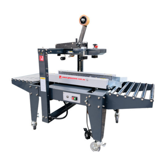
Page 6: Machine Description
2.3 Machine description... -
Page 7: Operation Description
3. OPERATION DESCRIPTION 3.1 Installation 1) Open the box. Please remove carefully to avoid damaging the machine. 2) Lift the machine to install casters (4 wheels), at the same time tighten the A nut to fix the casters in place. 3) Set the machine to the desired height, then tighten the B screw. - Page 8 4) Set up the machine and relocate to the desire place. 5) Attach the roller table to the machine body. 6) Load the tape head with tape. (Please refer to the tape head instruction manual.
- Page 9 7) Place a box filled with product on the in feed conveyor, position on the side drive belts and top section to accommodate the desired box width and height by using the width and height adjustment crank. Follow by adjusting the tow handle knobs against the sides of carton to secure the carton’s center.
-
Page 10: Operation Of Control Panel
3.2 OPERATION OF CONTROL PANEL Press to stop motors and belts. Press to start motors and belts. Emergency stop Circuit Breaker: When overload, circuit breaker will be activated. Press the button to reset the machine. Or it will reset automatically after 60 seconds. -
Page 11: Counter Instruction
4. COUNTER INSTRUCTION It is forbidden to cancel, disassemble, modify or not respect the implemented safety measures. In that case, the manufacturer will not be hold responsible for any possible damage caused. 2. Do not use the machine in a place where water and oil might splash 3. -
Page 12: Electric
5. ELECTRIC 5.1 Electric capacity 1) Power consumption Belt motor 0.18*2KVA Machine power consumption 0.4KVA Power socket requirement 0.5KVA 2) Power cable..1.25mm² 3) Machine input..AC 110V/2230V 1-Phase... -
Page 13: Electric Diagram
5.2 Electric diagram... - Page 16 ELECTRIC PARTS LIST FOR TMD-C26U KEY NO PART NO. DESCRIPTION P0302-010003500 SWITCH BOX (220~240V) P0302-010003600 SWITCH BOX (120V) KA02002900 Thermal Circuit Breaker KMB-3I(220V) P0305-030005600 Thermal Circuit Breaker KMB-5I(110V) 70560601 TERMINAL BLOCKS TB6P P0304-010003900 TERMINAL BLOCKS TB15-3 P0316-010000210 WIRE HOLDER, MG16A-10SG KA0900160 EMERGENCY STOP LABEL 7155BC20...
-
Page 17: Trouble Shooting
6. TROUBLE SHOOTING 6.1 Belt adjustment 1) Loosen the belt screw (A) to adjust the belt to a suitable tension screw (B). 6.2 Fuse Reset 1) Symptom: machine will not start to operate. A) Please check the power input. B) Release the E-stop button. C) Press circuit breaker to reset the fuse. -
Page 18: Parts List
7. PART LIST 7.1 Side belt... - Page 19 PARTS LIST FOR EXC-TMD-C26U KEY NO PART NO. DESCRIPTION Q’TY P01-042290B BELT COVER (L) P0902-0006700 BELT 50*1550 P02-0292600 PULLEY FOLLOWER P02-028510A PULLEY SHAFT P01-042350A GUIDE PLATE (L) P02-028520A ADJUSTMENT BLOCK P02-0285000 SUPPORT SCREW P01-042270B BELT SEAT(L) P02-0284900 ROLLER SHAFT P06-003200A ROLLER 2”...
- Page 20 PARTS LIST FOR EXC-TMD-C26U KEY NO PART NO. DESCRIPTION Q’TY CA3015L0 SPINDLE SUPPORT P02-0284400 ROD EXTENTION P02-0283800 HANDLE CRANK S.W:SPRING WASHER W:WASHER...
-
Page 21: Column
7.2 Column... - Page 22 PARTS LIST FOR EXC-TMD-C26U KEY NO PART NO. DESCRIPTION Q’TY P01-042240C TOP SEAT FRAME P01-044500C COVER PLATE P01-0433700 COMPRESSION ROLLER BAR CA100600 COPRESSION ROLLER P02-028230A COMPRESSION ROLLER SEAT P01-018470A FIXING PLATE CA101600 KNOB M10x63 P1114-010001500 TUBE PLUG 20*20 P01-042231B COLUMN (L) P01-044010A SPINDLE FIXING PLATE CA200200-01...
-
Page 23: Machine Body
7.3 Machine body... - Page 24 PARTS LIST FOR EXC-TMD-C26U KEY NO PART NO. DESCRIPTION Q’TY P01-042200C MACHINE FRAME P01-042680A MACHINE LEG P01-042690A ADJUSTABLE LEG P1107-0003300 CASTER P01-043490A TAPE HEAD HOLDING PLATE P01-042380B TABLE PLATE (REAR) P01-042390B TABLE PLATE (FRONT) P01-042191B CONTROL PANEL P01-042180A CONTROL BOX P06-0046700 SLIDING PLATE P01-0435300...
Need help?
Do you have a question about the GPCS-C26U and is the answer not in the manual?
Questions and answers