
Subscribe to Our Youtube Channel
Related Manuals for TechNexion TAM-3517


Summary of Contents for TechNexion TAM-3517
- Page 1 July 3 2011 TAM-3517 S YSTEM ON ODULE TAM-3517 HARDWARE MANUAL rev B TechNexion Arrow.com. Downloaded from...
- Page 2 TAM-3517 HARDWARE MANUAL rev B July 3 2012, TechNexion TAM-3517 TAM-3517 System on Module Hardware Manual Rev B Arrow.com. Arrow.com. Downloaded from Downloaded from...
-
Page 3: Table Of Contents
Revision ............................5 Care and Maintenance ........................6 General ............................ 6 Regulatory Information ......................6 Description ............................9 Block Diagram TAM-3517 System on Module ................. 10 Functional Block Diagram CPU ....................11 System Components ........................12 CPU: AM-3517........................12 5.1.1 AM-3517 Sitara ARM Processor Features ................ - Page 4 Pull-up or Pull-down Signals Description................. 59 8.14 Boot Option ........................... 59 Electrical Characteristics ........................ 60 Environmental Specifications ..................... 61 Mechanical Dimensions ......................62 11.1 TAM-3517 System on Module Dimensions ................62 Arrow.com. Arrow.com. Arrow.com. Arrow.com. Downloaded from Downloaded from Downloaded from...
-
Page 5: Revision
TAM-3517 HARDWARE MANUAL rev B July 3 2012, TechNexion Module Connection ........................63 12.1 Module Connector DDR2 SO-DIMM ..................63 12.2 Nut to Fix TAM-3517 Module to the Baseboard ..............64 Disclaimer ..........................65 Warranty ........................... 66 Contact Information ........................67 2 Revision Revision... -
Page 6: Care And Maintenance
TAM-3517 HARDWARE MANUAL rev B July 3 2012, TechNexion 3 Care and Maintenance 3.1 General Your device is a product of superior design and craftsmanship and should be treated with care. The following suggestions will help you. Keep the device dry. Precipitation, humidity, and all types of liquids or moisture can contain minerals that will corrode electronic circuits. - Page 7 TAM-3517 HARDWARE MANUAL rev B July 3 2012, TechNexion Arrow.com. Arrow.com. Arrow.com. Arrow.com. Arrow.com. Arrow.com. Arrow.com. Downloaded from Downloaded from Downloaded from Downloaded from Downloaded from Downloaded from Downloaded from...
- Page 8 TAM-3517 HARDWARE MANUAL rev B July 3 2012, TechNexion Federal Communications Commission (FCC) Unintentional emitter per FCC Part 15 This device has been tested and found to comply with the limits for a Class B digital device, pursuant to Part 15 of the FCC rules. These limits are designed to provide reasonable protection against harmful interference in a residential installation.
-
Page 9: Description
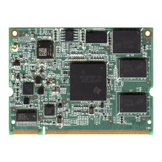
TAM-3517 HARDWARE MANUAL rev B July 3 2012, TechNexion 4 Description The TAM-3517 Is a highly integrated System on Module (SOM) containing the TI ARM Cortex A8 Sitara AM3517 processor, Wireless LAN, USB PHY, LAN PHY, CAN Bus, Memory and NAND Flash. -
Page 10: Block Diagram Tam-3517 System On Module
TAM-3517 HARDWARE MANUAL rev B July 3 2012, TechNexion 4.1 Block Diagram TAM-3517 System on Module Note: TAM-3517W includes Wi-Fi; TAM-3517 does not have Wi-Fi Arrow.com. Arrow.com. Arrow.com. Arrow.com. Arrow.com. Arrow.com. Arrow.com. Arrow.com. Arrow.com. Arrow.com. Downloaded from Downloaded from Downloaded from... -
Page 11: Functional Block Diagram Cpu
TAM-3517 HARDWARE MANUAL rev B July 3 2012, TechNexion 4.2 Functional Block Diagram CPU The functional block diagram of the AM3517 Sitara ARM Processor is shown below. Arrow.com. Arrow.com. Arrow.com. Arrow.com. Arrow.com. Arrow.com. Arrow.com. Arrow.com. Arrow.com. Arrow.com. Arrow.com. Downloaded from... -
Page 12: System Components
TAM-3517 HARDWARE MANUAL rev B July 3 2012, TechNexion 5 System Components 5.1 CPU: AM-3517 5.1.1 AM-3517 Sitara ARM Processor Features MPU Subsystem 600-Mhz Sitara™ ARM® Cortex-A8™ Core NEON SIMD Coprocessor and Vector floating point (FP) co-processor Memory Interfaces:... -
Page 13: Pmic: Tps-65023
TAM-3517 HARDWARE MANUAL rev B July 3 2012, TechNexion 5.2 PMIC: TPS-65023 5.2.1 TPS-65023 – Introduction The TPS65023 is an integrated Power Management IC for applications powered by one Li-Ion or Li-Polymer cell, and which require multiple power rails. The TPS65023 provides three highly efficient, step-down converters targeted at providing the core voltage, peripheral, I/O and memory rails in a processor based system. -
Page 14: Memory
5.3 Memory 5.3.1 Hynix H5PS1G63EFR (option 1) The TAM-3517 has a single channel 32 bit External Memory Interfaces (EMI) controller. The 32 bit wide channel is connected 16 bit wide to two Hynix H5PS1G63EFR DDR2 SDRAM Chips. The SDRAM_nCS0 signal is used to select them. -
Page 15: Micron Mt47H64M16 (Option 2)
July 3 2012, TechNexion 5.3.2 Micron MT47H64M16 (option 2) The TAM-3517 has a single channel 32 bit External Memory Interfaces (EMI) controller. The 32 bit wide channel is connected 16 bit wide to two Micron MT47H64M16 DDR2 SDRAM Chips. The SDRAM_nCS0 signal is used to select them. -
Page 16: Nanya Nt5Tu64M16Gg (Option 3)
July 3 2012, TechNexion 5.3.3 Nanya NT5TU64M16GG (option 3) The TAM-3517 has a single channel 32 bit External Memory Interfaces (EMI) controller. The 32 bit wide channel is connected 16 bit wide to two Nanya NT5TU64M16GG DDR2 SDRAM Chips. The SDRAM_nCS0 signal is used to select them. -
Page 17: Nand Flash
July 3 2012, TechNexion 5.4 NAND Flash 5.4.1 Micron MT29F4G16ABBDAHC NAND on the TAM-3517 is populated as Micron MT29F4G16ABBDAHC and connected 16 bit wide to the AM3517 GPMC bus. The default TAM-3517 supports the chip which provides 512MB of addressable space. -
Page 18: Mt29F2G16Abdhc-Et
TAM-3517 HARDWARE MANUAL rev B July 3 2012, TechNexion 5.4.2 MT29F2G16ABDHC-ET NAND on the TAM-3517 is populated as Micron MT29F2G16ABDHC and connected 16 bit wide to the AM3517 GPMC bus. The TAM-3517 supports the chip which provides 256MB of addressable space. -
Page 19: Network Phy: Smsc Lan8710A
TAM-3517 HARDWARE MANUAL rev B July 3 2012, TechNexion 5.5 Network PHY: SMSC LAN8710A SMSC's LAN8710A is a high-performance, small-footprint, low-power 10BASE-T/100BASE-TX transceivers specifically designed for today's consumer electronics, industrial and enterprise applications. The LAN8710A is the industry's smallest footprint solution with up to 40% lower power consumption than existing SMSC transceivers. -
Page 20: Usb Phy
USB session with only 12 pins. 5.7 WiFi Module (This module is included on the TAM-3517W; the TAM-3517 does not have Wi-Fi) The Marvell® 88W8686 is a low-power highly-integrated IEEE 802.11g/b MAC/Baseband/RF WLAN system-on-chip (SoC), designed to support IEEE 802.11g payload data rates of 6, 9, 12, 18, 24, 36, 48, and 54 Mbps, as well as 802.11b data rates of 1, 2, 5.5, and 11 Mbps. -
Page 21: I-Pex Connector
TAM-3517 HARDWARE MANUAL rev B July 3 2012, TechNexion 5.7.2 I-PEX Connector Arrow.com. Arrow.com. Arrow.com. Arrow.com. Arrow.com. Arrow.com. Arrow.com. Arrow.com. Arrow.com. Arrow.com. Arrow.com. Arrow.com. Arrow.com. Arrow.com. Arrow.com. Arrow.com. Arrow.com. Arrow.com. Arrow.com. Arrow.com. Arrow.com. Downloaded from Downloaded from Downloaded from Downloaded from... -
Page 22: Eeprom
TAM-3517 HARDWARE MANUAL rev B July 3 2012, TechNexion 5.8 EEPROM The read-only EEPROM is used to store board and manufacturing information, such as the MAC Address data. The EEPROM is connected by I2C1 with the default address 000. The CAT24C02 is a 2−Kb CMOS Serial EEPROM devices organized internally as 16 pages 16 bytes each. -
Page 23: How To Use The Multiplex Mode
Hsusb2_data3 transceiver Bidirectional data bus GPIO_182 General-purpose IO 182 Mm_fsusb2_txen_n Transmit enable Safe_mode Table 1: Example of pin 90 on the TAM-3517 module and the different functions for each multiplex mode (see chapter 7) Arrow.com. Arrow.com. Arrow.com. Arrow.com. Arrow.com. Arrow.com. -
Page 24: Tam-3517 Module Pin Description
TAM-3517 HARDWARE MANUAL rev B July 3 2012, TechNexion 7 TAM-3517 Module Pin Description Pin # Ball # Pin Name mode V type description DC 5V Power DC 5V Power GND GND Ground VRTC Power Right stereo mixer-channel CODEC1 line output. Nominal output RLINEOUT level is 1.0 VRMS. - Page 25 TAM-3517 HARDWARE MANUAL rev B July 3 2012, TechNexion Pin # Ball # Pin Name mode V type description I2C Serial Bidirectional I2C3_SDA Data. Output is open drain GPIO_185 General-purpose IO 185 Safe_mode I2C Serial Bidirectional I2C2_SDA Data. Output is open drain...
- Page 26 TAM-3517 HARDWARE MANUAL rev B July 3 2012, TechNexion Pin # Ball # Pin Name mode V type description UART3 Request To Send , UART3_RTS_SD IR enable GPIO_164 General-purpose IO 164 Safe_mode USB_RESET UART3 Clear to Send UART3_CTS_RCTK 0 (input), Remote TX (output)
- Page 27 TAM-3517 HARDWARE MANUAL rev B July 3 2012, TechNexion Pin # Ball # Pin Name mode V type description CCDC_VD CCDC vertical sync Uart4_cts UART4 Clear To Send GPIO_97 General-purpose IO 97 Hw_dbg2 Debug signal 2 Safe_mode CDCC_Field CCDC field ID signal...
- Page 28 TAM-3517 HARDWARE MANUAL rev B July 3 2012, TechNexion Pin # Ball # Pin Name mode V type description MMC1_CLK MMC/ SD Output Clock 1.8/ GPIO_120 General-purpose IO 120 Safe_mode LED1 Ether_linl_act_LEDn MMC1_DAT2 MMC/ SD Card Data Bit 2 Slave data out, master data Mcspi2_somi 1.8/...
- Page 29 TAM-3517 HARDWARE MANUAL rev B July 3 2012, TechNexion Pin # Ball # Pin Name mode V type description LCD_ENVDD General-purpose IO 138 MMC2_DAT6 MMC/SD Card Data bit 6 Direction control for CMD AD13 MMC2_DIR_CMD signal case an external transceiver is used...
- Page 30 TAM-3517 HARDWARE MANUAL rev B July 3 2012, TechNexion Pin # Ball # Pin Name mode V type description TV analog output S-VIDEO: TV_OUT2 tv_out2 MCSPI1_CLK SPI Clock MMC2_DAT4 MMC/SD Card Data bit 4 AE14 GPIO_171 General-purpose IO 171 Safe_mode 3.3 V Power...
- Page 31 TAM-3517 HARDWARE MANUAL rev B July 3 2012, TechNexion Pin # Ball # Pin Name mode V type description MCSPI2_CLK SPI clock Dedicated for external Hsusb2_data7 transceiver Bidirectional AD16 data bus GPIO_178 General-purpose IO 178 Safe_mode slave data out, master data...
- Page 32 TAM-3517 HARDWARE MANUAL rev B July 3 2012, TechNexion Pin # Ball # Pin Name mode V type description LCD Horizontal DSS_HSYNC Synchronization AD22 GPIO_67 General-purpose IO 67 Hw_dbg13 Debug signal 13 Safe_mode DSS_Data2 LCD Pixel Data bit 2 AC23...
- Page 33 TAM-3517 HARDWARE MANUAL rev B July 3 2012, TechNexion Pin # Ball # Pin Name mode V type description DSS_Data7 LCD Pixel Data bit 7 UART1_RX UART1 Receive data AA23 GPIO_77 General-purpose IO 77 Hw_dbg15 Debug signal 15 Safe_mode DSS_Data4...
- Page 34 TAM-3517 HARDWARE MANUAL rev B July 3 2012, TechNexion Pin # Ball # Pin Name mode V type description DSS_Data19 LCD Pixel Data bit 19 Slave data in, master data MCSPI3_SIMO DSS_Data3 LCD Pixel Data bit 3 GPIO_89 General-purpose IO 89...
- Page 35 TAM-3517 HARDWARE MANUAL rev B July 3 2012, TechNexion Pin # Ball # Pin Name mode V type description UART1_CTS UART1 Clear To Send GPIO_150 General-purpose IO 150 Safe_mode Not Connected UART1_RTS UART1 Clear To Send GPIO_149 General-purpose IO 149...
- Page 36 TAM-3517 HARDWARE MANUAL rev B July 3 2012, TechNexion Pin # Ball # Pin Name mode V type description GPMC_nCS4 GPMC Chip Select 4 External DMA request 1 (system expansion). Level Sys_ndmareq1 (active low) or edge (falling) selectable. PWM or event for GP timer...
- Page 37 TAM-3517 HARDWARE MANUAL rev B July 3 2012, TechNexion Pin # Ball # Pin Name mode V type description GPMC_A7 GPMC Address bit 7 GPIO_40 General-purpose IO 40 Safe_mode GPMC_A5 GPMC_Address bit 5 GPIO_38 General-purpose IO 38 Safe_mode GPMC_A1 GPMC_Address bit 1...
- Page 38 TAM-3517 HARDWARE MANUAL rev B July 3 2012, TechNexion Pin # Ball # Pin Name mode V type description UART1_TX UART1 Transmit Data AA19 GPIO_148 General-purpose IO 148 Safe_mode MCBSP2_DX Transmitted Serial Data GPIO_119 General-purpose IO 119 Safe_mode UART1_RX UART1 receive data...
- Page 39 TAM-3517 HARDWARE MANUAL rev B July 3 2012, TechNexion Pin # Ball # Pin Name mode V type description MCBSP4_DX Transmitted serial data GPIO_154 General-purpose IO 154 USB data. Used as VP in 4- Mm_fsusb3_txdat pin VP_VM mode. Safe_mode GPMC_nWP...
-
Page 40: Definitions
X=Pin on other chip than AM-3517 The GPMC pins are restricted and cannot be used in GPIO mux mode unless special TAM- 3517 modules are bought without onboard NAND IC. GPMC nCS0 is connected to NAND IC on TAM-3517. assembled 1. MODE: Multiplexing mode number. -
Page 41: Signal Description
TAM-3517 HARDWARE MANUAL rev B July 3 2012, TechNexion 8 Signal Description 8.1 External Memory Interfaces – GPMC Signals Description The General Purpose Memory Controller (GPMC) is dedicated to interfacing external memory devices: such as NOR Flash, NAND Flash, Pseudo SRAM, SRAM or Field programmable Gate... - Page 42 External indication of wait GPMC WAIT1 External indication of wait GPMC WAIT2 External indication of wait GPMC WAIT3 External indication of wait Note 1: GPMC nCS0 is connected to NAND IC on TAM-3517. Arrow.com. Arrow.com. Arrow.com. Arrow.com. Arrow.com. Arrow.com. Arrow.com.
-
Page 43: Video Interfaces -Cam Signals Description
TAM-3517 HARDWARE MANUAL rev B July 3 2012, TechNexion 8.2 Video Interfaces –CAM Signals description SIGNAL NAME DESCRIPTION TYPE PIN TAM-3517 CCDC_HD Camera Horizontal Synchronization CCDC _VD Camera Vertical Synchronization CCDC _data0 Camera digital image data bit 0 CCDC _data1... -
Page 44: Video Interfaces - Dss Signals Description
LCD Pixel Data bit 22 Dss_data23 LCD Pixel Data bit 23 LCD_PON LCD Enable LCD_ENVDD LCD Voltage On The TAM-3517 can easily be connected to a 18 or 24 bit TTL panel by following the following table. DSS_D 24 bit 18 bit Dss_data0 Dss_data1 Dss_data2 Arrow.com. -
Page 45: Video Interfaces - Tv Signals Description
TAM-3517 HARDWARE MANUAL rev B July 3 2012, TechNexion Dss_data3 Dss_data4 Dss_data5 Dss_data6 Dss_data7 Dss_data8 Dss_data9 Dss_data10 Dss_data11 Dss_data12 Dss_data13 Dss_data14 Dss_data15 Dss_data16 Dss_data17 Dss_data18 Dss_data19 Dss_data20 Dss_data21 Dss_data22 Dss_data23 8.4 Video Interfaces – TV Signals Description The video encoder converts RGB video signals to conform to the NTSC/PAL standard analog video. -
Page 46: Serial Communication Interfaces - I
TAM-3517 HARDWARE MANUAL rev B July 3 2012, TechNexion 8.5 Serial Communication Interfaces – I C Signals Description The device contains multimaster high-speed (HS) inter-integrated circuit (I2C) controllers, each of which provides an interface between a local host (LH), such as the microprocessor unit (MPU) subsystem, and any I2C-bus-compatible device that connects through the I2C serial bus. -
Page 47: Serial Communication Interfaces - Mcbsp Lp Signals Description
TAM-3517 HARDWARE MANUAL rev B July 3 2012, TechNexion 8.6 Serial Communication Interfaces – McBSP LP Signals Description The multichannel buffered serial port (McBSP) provides a full-duplex direct serial interface between the device and other devices in a system such as other application chips (digital base band), audio and voice codec, etc. -
Page 48: Serial Communication Interfaces - Mcspi Signals Description
TAM-3517 HARDWARE MANUAL rev B July 3 2012, TechNexion 8.7 Serial Communication Interfaces – McSPI Signals Description The multichannel serial port interface (McSPI) is a master/slave synchronous serial bus. The McSPI modules differ as follows: SPI1 and SPI2 support up to four peripherals. -
Page 49: Serial Communication Interfaces - Uarts Signals Description
TAM-3517 HARDWARE MANUAL rev B July 3 2012, TechNexion 8.8 Serial Communication Interfaces – UARTs Signals Description The module contains three universal asynchronous receiver/transmitter (UART) devices controlled by the microprocessor unit (MPU): UART1 and UART2 are pinned out for use as UART devices only. -
Page 50: Serial Communication Interfaces - Usb Signals Description
July 3 2012, TechNexion 8.9 Serial Communication Interfaces – USB Signals Description The USB Host is connected to the SMSC USB3320 PHY on TAM-3517 The USB3320 is a highly integrated full featured Hi-Speed USB 2.0 transceiver based on SMSC’s proven ULPI interface. It supports a wide variety of different reference clock frequencies with one single part, as well as accepting clocking from crystal/resonators and the ULPI 60 MHz Clock-In mode. -
Page 51: Serial Communication Interfaces - Hecc Can Bus Signals Description
PIN TAM-3517 HECC1_TXD Transmit serial data pin HECC1_RXD Receive serial data pin TechNexion recommends using the TI SN65HVDA540QDR CAN Transceiver on your Baseboard. The SN65HVDA540 meets or for use in exceeds the specifications of the ISO 11898 standard applications employing a Controller Area Network (CAN). The device is qualified for use in automotive applications. -
Page 52: Removable Media Interfaces - Mmc/ Sdio Signals
TAM-3517 HARDWARE MANUAL rev B July 3 2012, TechNexion 8.2 Removable Media Interfaces – MMC/ SDIO Signals The multimedia card high-speed/SD/SD I/O (MMC/SD/SDIO) host controller provides an interface between a local host (LH) such as a microprocessor unit (MPU) or digital signal processor (DSP) and either MMC, SD memory cards, or SDIO cards and handles MMC/SD/SDIO transactions with minimal LH intervention. -
Page 53: Test Interfaces - Jtag Signals Description
TAM-3517 HARDWARE MANUAL rev B July 3 2012, TechNexion 8.4 Test Interfaces – JTAG Signals Description The target debug interface of the device uses the five standard IEEE 1149.1 (JTAG) signals (nTRST, TCK, TMS, TDI, and TDO), a return clock (RTCK) to meet the clocking requirements of the ARM968 processor, and two instrumentations pins (EMU0, EMU1). - Page 54 TAM-3517 HARDWARE MANUAL rev B July 3 2012, TechNexion See Photo for the location of the solder pads. Solder at the orange pads Arrow.com. Arrow.com. Arrow.com. Arrow.com. Arrow.com. Arrow.com. Arrow.com. Arrow.com. Arrow.com. Arrow.com. Arrow.com. Arrow.com. Arrow.com. Arrow.com. Arrow.com. Arrow.com. Arrow.com.
-
Page 55: Power Supplies Signals Description
TAM-3517 HARDWARE MANUAL rev B July 3 2012, TechNexion 8.5 Power Supplies Signals description Power Supply Signals SIGNAL NAME DESCRIPTION TYPE PIN TAM-3517 DC 5V Power 5V DC 5V Power 5V DC 5V Power 5V DC 5V Power 5V DC 5V... -
Page 56: System And Miscellaneous Signals Description
Power On Reset SYS_CLKOUT1 Configurable output clock1 SYS_nRESPWARM Warm Boot Reset (open drain output) SYS_nRESPWRON will reset the module when pulled low, it will reset TAM-3517, TPS65023, LAN ransceiver, USB PHYand WiFi simultaneously. 8.7 Touch Interupt Signal Description SIGNAL NAME DESCRIPTION... -
Page 57: Analog Audio Signals Description
TAM-3517 HARDWARE MANUAL rev B July 3 2012, TechNexion 8.10 Analog Audio Signals Description The TDM-3730 contains the TLV320AIC23B Stereo Audio Codec. MICROPHONE INPUT Signals Description SIGNAL NAME DESCRIPTION TYPE PIN TAM-3517 Buffered amplifier input suitable for use with MICIN electret-microphone capsules. -
Page 58: Ethernet Signals Description
Transmit Positive Output (normal) LED1 Link activity LED Indication LED2 Link Speed LED Indication 8.12 LED Signals Description The TAM-3517 System on Module contains 3 onboard LEDs with following functions: LED NAME DESCRIPTION LED0 WiFi: Active LED1 Power: System works... -
Page 59: Pull-Up Or Pull-Down Signals Description
TAM-3517 HARDWARE MANUAL rev B July 3 2012, TechNexion 8.13 Pull-up or Pull-down Signals Description Pin # Signal Name Mode Voltage Resistor Pull up/down I2C3_sda 4.7kΩ GPIO_185 Safe mode I2C3 SCL 4.7kΩ GPIO_184 safemode I2C2 SDA 4.7kΩ GPIO_183 Safe_mode I2C2 SCL 4.7kΩ... -
Page 60: Electrical Characteristics
TAM-3517 HARDWARE MANUAL rev B July 3 2012, TechNexion 9 Electrical Characteristics PARAMETER UNIT Absolute maximum Ratings Second supply voltage range for Vdds -0.5 2.25 1.8-V I/O macros Analog power supply for 3.3-V VDDA_3P3V_USBPHY -0.5 USB transceiver VDDSHV 3.3-/1.8-VV power supply -0.5... -
Page 61: Environmental Specifications
TAM-3517 HARDWARE MANUAL rev B July 3 2012, TechNexion 10 Environmental Specifications Commercial: 0° to 70° C Temperature Extended: -20° to 70° C (no WiFi) Industrial: -40° to 85° C (no WiFi) Humidity 10-90% 67.6x 50x 3.4 mm (2⅝x 2x ¼ inch) -
Page 62: Mechanical Dimensions
July 3 2012, TechNexion 11 Mechanical Dimensions 11.1 TAM-3517 System on Module Dimensions Dimensions in mm Note: 2D (DXF) and 3D(STEP) files are available for download at the Technexion website. (Service and support/ Downloads/ ARM CPU Modules/ TAM-3517) Arrow.com. Arrow.com. - Page 63 TAM-3517 HARDWARE MANUAL rev B July 3 2012, TechNexion 12 Module Connection 12.1 Module Connector DDR2 SO-DIMM To mount the TAM-3517 module on the baseboard it isrecommended to use a connector with the following specifications: DDR II SO-DIMM 200pin SMT ...
- Page 64 Note 1: Always design the above mounting nut/pose on your custom baseboard and fasten the TAM-3517 to ensure a solid connection and counter vibration prone applications. Note 2: On a custom baseboard always connect the mounting nut/pose to the baseboard general system GND section.
- Page 65 Information published by TechNexion regarding third-party products or services does not constitute a license from TechNexion to use such products or services or a warranty or endorsement thereof. Use of such information may require a license from a third party under the patents or other intellectual property of the third party, or a license from TechNexion under the patents or other intellectual property of TechNexion.
- Page 66 Accessories or parts added to Products after the Products shipped from TechNexion and, Accessories, or parts that are not assembled in TechNexion facilities. d. All warranty is voided if the TechNexion warranty label or serial number is removed, illegible, or missing Arrow.com.
- Page 67 TAM-3517 HARDWARE MANUAL rev B July 3 2012, TechNexion 15 Contact Information TechNexion Headquarters: Address: 17F-1, No. 16, Jian Ba Road, Chung Ho City, 23511, Taipei, Taiwan E-mail: sales@technexion.com Website: www.technexion.com Telephone: +886-2-8227 3585 Fax: +886-2-8227 3590 Arrow.com. Arrow.com. Arrow.com.
Need help?
Do you have a question about the TAM-3517 and is the answer not in the manual?
Questions and answers