Table of Contents
Advertisement
Quick Links
Advertisement
Chapters
Table of Contents

Related Manuals for sauter modu600-LO

Summary of Contents for sauter modu600-LO
- Page 1 Operating instructions D100408262...
- Page 3 Operating instructions D100408262 3/60 D100408262 R: 02, V: 01...
-
Page 4: Table Of Contents
Contents Contents ............................4 Change index ........................... 6 Preface ............................7 modulo 6 I/O modules and the local modu600-LO operation unit ......... 7 About this manual ........................8 Purpose and intended readership ................. 8 Abbreviations ......................... 8 Symbols and terms used in this manual ................ 8 Firmware version of modu600-LO ................. - Page 5 Contents Didact Gothic – Regular Font Copyright ..............55 11.1 Supported characters (Didact Gothic – Regular) ............58 11.2 5/60 D100408262 R: 02, V: 01...
-
Page 6: Change Index
Change index Change index Description Date 01.02 Market introduction Sept. 2019 02.01 Enhancements as of AS firmware Version 1.2.3 Mar. 2022 New chapters § 9.6, 0 6/60 R: 02, V: 01 D100408262... -
Page 7: Preface
(override), e.g. during acceptance or maintenance work. modu600-LO is a universal module for all modulo 6 I/O modules that can be plugged in or off on the modules. The module does not need dedicated programming or configuration and receives all of the necessary information from the I/O module. -
Page 8: About This Manual
About this manual About this manual Purpose and intended readership This manual is intended for people who use modu600-LO to monitor and operate building management systems. To understand the manual, a certain degree of knowledge of building management, HVAC and control technology is required. -
Page 9: Firmware Version Of Modu600-Lo
About this manual Firmware version of modu600-LO 2.4.1 Firmware changes LOI FW Change Distributed Distribution version with AS FW date 0.12.148 R First official release 1.0.0 Sept. 2019 0.13.172 R New firmware version 1.2.0 Sept. 2020 1.0.178 R New firmware version. Changes in operating principles. -
Page 10: Safety Information
The module automatically reads the information from the I/O module and refreshes the displayed content. The firmware of the modu600-LO is only updated upon restart, if necessary. The modu600-LO should not be unplugged during this phase. More on this in § 9.5. ➔ No application to means of transport. -
Page 11: Standards And Directives
Safety information Standards and directives Type of protection IP30 (EN 60730-1) Protection class III (EN 60730-1) Environment class 3K3 (IEC 60721) CE conformity EMC Directive 2014/30/EU EN 61000-6-1 according to EN 61000-6-2 EN 61000-6-3 EN 61000-6-4 EN 50491-5-1 EN 50491-5-2... -
Page 12: Product Structure
Product structure Product structure This product is classified under building management system, in the section “HVAC automation modulo 6”. 91,141 EY6LO00F001 Local operating and indicating unit for I/O module modu600-LO Compatible with: 91,111 EY6IO30F001 16× DI/CI inputs, I/O module... -
Page 13: Further Documentation
Further documentation Further documentation P100018024 DE: D100489815 FR: D100490791 EN: D100490789 DE: D100380638 FR: D100380639 EN: D100380640 13/60 D100408262 R: 02, V: 01... -
Page 14: Hardware Description
Hardware description Hardware description General properties Width 52.5 mm (3 HP) Height 57.0 mm Depth 43.5 mm, incl. clips 41.67 mm, without clips Protection IP00 Back ▪ 4 clips ▪ 4 spring contacts 24 VDC UART RX UART TX ▪... - Page 15 Hardware description Front LOGO LCD colour screen ▪ 240 × 240 pixels ▪ 1.44 inches ▪ 25.8 × 25.8 mm² ▪ Colour coding like I/O module Buttons ▪ Cancel, back ▪ Back, smaller ▪ Forward, bigger ▪ Confirm, select...
- Page 16 Hardware description Installation instructions 16/60 R: 02, V: 01 D100408262...
-
Page 17: Functionality And Operation
“override “ to TRUE. Any value set to the priority array, e. g. AUTO mode (for SAUTER, priority 16) or manual operation over BMS (usually priority 8) is ignored, as long as a modu600-LO or modulo 6 App override is active. -
Page 18: Navigation Structure
I/O channels in the I/O module. There are usually 16 channels per module, except for modu650-IO with 6 channels and modu672-IO with 12 channels. modu600-LO reads the necessary information from the module when it is plugged in and supplied with power and it automatically adjusts the structure. -
Page 19: State Icons
Functionality and operation State icons The state icons map the state of the BACnet object that is coupled with this channel. Thus, a non-configured channel does not get any of the BACnet state icons. Offline BACnet object not accessible... -
Page 20: Operation
Functionality and operation Operation The operation takes place using the 4 push buttons. The push buttons are used to switch the focus between the different active buttons or change an output value (in edit mode). The push-button confirms a selection or a value change or displays a new view. - Page 21 Functionality and operation Push- Function(s) button On the overview page: This button is used to change the focus from the central text field to the next channel, forwards or backwards. If a channel is in edit mode, the value is changed using the buttons. For analogue values, the standard step is 1/1000 of the dynamic range (0.01 V for 0…10 V).
-
Page 22: Views
The “IO” tab displays the same information on the I/O module on which modu600-LO is located. Thus, it is not necessary to remove modu600- LO and the modu6** I/O module to read this information. -
Page 23: Figure 2 Areas In The Overview
Functionality and operation Detailed view The detailed view offers further information for a selected I/O channel. The view shows how the channel has been configured by the project, with a label, signal type and value. This view allows to manually configure unused channels. - Page 24 Functionality and operation Blue: Configured Grey: Not configured Red: Alarm (flashing): Orange: Manual “Inwards” Input: “Outwards” Output: Signal component area The components differ by signal type between digital (LED, switch) and analogue signals (bar, slider) and between active (green) and not active (grey). The components show the current value in graphical form, either as IN/OUT or on a relative scale.
- Page 25 Functionality and operation Focus on a channel: For configured channels, the defined label is displayed on the first line. If this text is longer than the available space it is displayed as a running text. Details are displayed on the second line: •...
-
Page 26: Table 1 Summary Of The Signal Components And The Central Text Field Based On Signal Type And Bacnet Object
Functionality and operation Obj. Icons Value Line 2 The bottom circle stands BI Value: IAcTxt State for: OFF, LOW, “0”, inactive Top circle, stands for: BI Value: AcTxt State ON, HIGH, “1”, active The white circle in the BO Value:... -
Page 27: Figure 3 Areas In The List View
Functionality and operation 7.5.2 List view Channels 1-8 Channel type I/O Channel label Channel label Channel type I/O Channels 9-16 Figure 3 Areas in the list view Channel type area The triangles show whether the channels are inputs or outputs. The buttons change the focus, which is indicated by the blue colour. - Page 28 Functionality and operation Channel label source This area displays the channels with their number and the configured label. Non- configured channels do not have labels. The buttons change the focus, which is indicated by the blue text colour. When the button is pressed the detailed view of the selected channel is displayed.
-
Page 29: Figure 4 Areas In The Detailed View
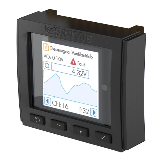
Functionality and operation 7.5.3 Detailed view Label Channel type I/O, setting, state (Secure value on), value, (Override RESET) Chart/Live view of signal 5 minutes Previous, channel no., terminal no., Next Figure 4 Areas in the detailed view Label area For configured channels, the label corresponds to the definition created in CASE Engine. -
Page 30: Table 2 Configuration Options Based On Channel Type
Functionality and operation Channel DI/CI DI/CI/DO_OC DO_R type 0 (2)… 10 V 0 (2)… 10 V 0 (2)… 10 V Selection Digital In Digital In Digital Out (BACnet (BI, MI) (BI, MI) (BO, MO) 0 … 20 mA Ni1000... - Page 31 Functionality and operation Chart area This area graphically displays the development of the value over the last 5 minutes. Important note The sampling is performed approx. every 1.5 seconds. Because the cycle time of the station can be as low as 50 ms, this display and the measurement cannot be viewed as a precision measurement or as evidence.
- Page 32 Functionality and operation Digital signals Input configured Input not configured Digital Input Value: The state will be displayed with the The non-configured channel is indicated as “unused”. The label and state are empty. Security IAcTxt/AcTxt texts of the associated BACnet object (default 0/1).
- Page 33 Functionality and operation Output configured Output not configured Digital Output Digital Output (Relay, DO_R) Digital Output (Open Collector, DO_OC) The non-configured channel is indicated as buttons can be used to set “unused”. The label and state are empty. Security...
- Page 34 Functionality and operation Analogue signals Input configured Input not configured Value: Interface-Value + Unit (BACnet properties Selection modu631-IO: of associated object) ▪ 0–10 V In Fallback: ▪ 0–2.5 k In ▪ Setting 0 … 10 V → Unit V ▪...
-
Page 35: Table 3 Nominal And Effective Ranges Of The Analogue Signals
Functionality and operation Output configured Output not configured Analogue outputs can be configured as: buttons can be used to set the focus to the value field, and the button puts it into the ▪ 0–10 V Out edit mode. - Page 36 Functionality and operation value and the set unit are displayed on the modu600-LO. If the unit is missing or the connection is broken, the unscaled value and unit are displayed. For analogue outputs (AO), the manual override is only shown as a % of the nominal range.
- Page 37 Functionality and operation Multi-state signals Multi-state signals are combinations of digital signals that have been assigned to a single multi-state BACnet object. For this reason, there are no unconfigured multi-states. Input configured Input not configured Detailed view per multi-state...
- Page 38 Functionality and operation Important information Multi-state BACnet objects in modulo 6 can define up to 8 states. modu600-LO can display up to 4 steps or states as multi-state. In comparison, it was only possible to control 2 channels with modu650F002 (0 – I – II).
- Page 39 Reference number: EY6LO00F001 Name: Local Operation and Indication Unit Serial number: ######### Date of Production: ######### Firmware version: v#.#.#b### Copyright: Fr. SAUTER AG © 2019 I/O module info view Reference number: EY6IO**F001 Name: Serial number: ######### Date of Production: ######### Firmware version: v#.#.#b###...
-
Page 40: Settings In Case
Functionality and operation Settings in CASE The following settings in CASE affect the display and functionality of modu600-LO: 7.6.1 States in binary and multi-state objects Binary objects have two text properties that can be used to assign a text for the active or... -
Page 41: Figure 5 Context Menu Of A Modulo 6 Station And Path To The Loi Label Editor
Functionality and operation Figure 5 Context menu of a modulo 6 station and path to the LOI label editor Similarly to the printed labels in modulo 5, the editor is set up in the form of a table. The editor offers a general configuration but also the option of individual configurations based on channel type (AI, AO, BI, BO, MI, MO, CI). -
Page 42: Figure 7 Tab For Individual Configuration, Which Is Activated Via The Checkbox
Functionality and operation Figure 7 Tab for individual configuration, which is activated via the checkbox The description is created by combining various fields, with each field having a specific length. The information in the fields is selected from a list and different information from the hardware and the software is available: Selection from the “Field”... -
Page 43: Figure 9 Table Display Of The Configured Labels
Functionality and operation Figure 9 Table display of the configured labels 7.6.3 Time setting for the dimming of the backlight This setting is made globally for all modules of one station. The "Parameter for local operating unit" are located on the shaft side of a modulo 6 station. The "Edit" button... -
Page 44: Figure 11 Configuration Dialogue For An Analog Output Signal
Functionality and operation 7.6.4 Setting the "Secure Value" value The value "Secure Value" is shown on the modu600-LO with the symbol . This value is configured with CASE Engine and for output signals only. You can select the modulo 6 station, double-click and the map appears. Then select the output signal on the right piano. -
Page 45: Figure 12 Module And Signal Configuration Table
Functionality and operation Figure 12 Module and signal configuration table. When restarting the Station after it has been shut down, the overridden signals are maintained as long as the modu600-LO remains plugged in. 45/60 D100408262 R: 02, V: 01... -
Page 46: Maintenance
Maintenance Maintenance modu600-LO does not require any maintenance. However, the following is recommended: • The module does not have a protective screen. Do not touch the screen, either with your fingers or with sharp objects • If necessary, clean the screen with a dry, clean microfibre cloth with due care •... -
Page 47: Faq
What does this icon mean? This icon indicates that the communication between modu600-LO and the I/O module is not working even though the I/O module is supplying power to modu600-LO Make sure that the module is installed correctly, that the spring contacts are clean and undamaged, and that the contact areas of the I/O module are clean and free. -
Page 48: How Can I Change The Language Of The Gui
Out of Service, or has been overridden via LOI, and the output is in a valid area. Thus, the behaviour is identical to that of moduWeb Unity and SAUTER Vision Center. Table 4 Truth table for displaying the icons How can I change the language of the GUI? modu600-LO does not support localisation. - Page 49 Updating the firmware takes − between 90 and 120 seconds to be carried out completely for the first 12 I/O modules − between 180 and 240 seconds for the next I/O modules 49/60 D100408262 R: 02, V: 01...
-
Page 50: What Happens With Polarity = Reverse
Table 5 PV and polarity of digital outputs This inversion is controlled by the I/O module and is not visible on the modu600-LO. The display of the binary switch is not inverted. With a pull-up resistor as load, Vout=Vdc... -
Page 51: Behaviour Of Backlight
Behaviour of backlight The backlight has 2 brightness levels. The darker level has been defined as 15% of the maximum brightness. The brighter level can be configured as a % of the maximum brightness in CASE Engine (see 7.6.3). It makes no sense to configure the brightness lower than 15%. - Page 52 52/60 R: 02, V: 01 D100408262...
-
Page 53: Figures
Figures Figures Figure 1 Schema of the different views in modu600-LO and the navigation between the views ....................... 18 Figure 2 Areas in the overview ................... 23 Figure 3 Areas in the list view ..................... 27 Figure 4 Areas in the detailed view ..................29 Figure 5 Context menu of a modulo 6 station and path to the LOI label editor .... -
Page 54: Tables
Tables Tables Table 1 Summary of the signal components and the central text field based on signal type and BACnet object ................26 Table 2 Configuration options based on channel type ............30 Table 3 Nominal and effective ranges of the analogue signals......... 35 Table 4 Truth table for displaying the icons............... -
Page 55: Annexe
Annexe Annexe Didact Gothic – Regular Font Copyright 11.1 Copyright (c) 2009, 2010, 2011 Daniel Johnson (il.basso.buffo@gmail.com) This Font Software is licensed under the SIL Open Font License, Version 1.1. This license is copied below and is also available with an FAQ at: http://scripts.sil.org/OFL... - Page 56 Annexe “Modified Version” refers to any derivative made by adding to, deleting, or substituting – in part or in whole – any of the components of the Original Version, by changing formats or by porting the Font Software to a new environment.
- Page 57 Annexe THE FONT SOFTWARE IS PROVIDED “AS IS”, WITHOUT WARRANTY OF ANY KIND, EXPRESS OR IMPLIED, INCLUDING BUT NOT LIMITED TO ANY WARRANTIES OF MERCHANTABILITY, FITNESS FOR A PARTICULAR PURPOSE AND NONINFRINGEMENT OF COPYRIGHT, PATENT, TRADEMARK, OR OTHER RIGHT.
- Page 58 Annexe Supported characters (Didact Gothic – Regular) 11.2 !"#$%&'()*+,-./ ˘˙˚˛˜˝ ṠṡṢṣṪṫṬṭṮṯ 0123456789:;<=>? ̀́̂̃̄̆̇̈ ṰṱṴṵ @ABCDEFGHIJKLMNO ̑̒̓̔ ẀẁẂẃẄẅ PQRSTUVWXYZ[\]^_ ̧̨̣̤̥̦̩̭ ẒẓẔẕẖẞ `abcdefghijklmno ̵̶̷̸̰̱̲ ẠạẬậ pqrstuvwxyz{|}~ ͂̓̈́ͅ ẸẹẼẽ ¡¢£¤¥¦§¨©ª«¬-®¯ ͞ ͟ ỆệỊịỌọ °±²³´µ¶·¸¹º»¼½¾¿ ʹ͵ͺ; Ộộ ÀÁÂÃÄÅÆÇÈÉÊËÌÍÎÏ ΄΅Ά·ΈΉΊΌΎΏ Ụụ ÐÑÒÓÔÕÖ×ØÙÚÛÜÝÞß ΐΑΒΓΔΕΖΗΘΙΚΛΜΝΞΟ ỲỳỸỹ...
- Page 59 Annexe ꞋꞌꞍ fifl 59/60 D100408262 R: 02, V: 01...
- Page 60 Annexe © Fr. Sauter AG Im Surinam 55 CH-4016 Basel Tel. +41 61 - 695 55 55 Fax +41 61 - 695 55 10 www.sauter-controls.com info@sauter-controls.com 05.04.2022 60/60 R: 02, V: 01 D100408262...
Need help?
Do you have a question about the modu600-LO and is the answer not in the manual?
Questions and answers