Table of Contents
Advertisement
Quick Links
Using your
NanoCore12DXC32 Quick-
Start Package
1. Getting Started
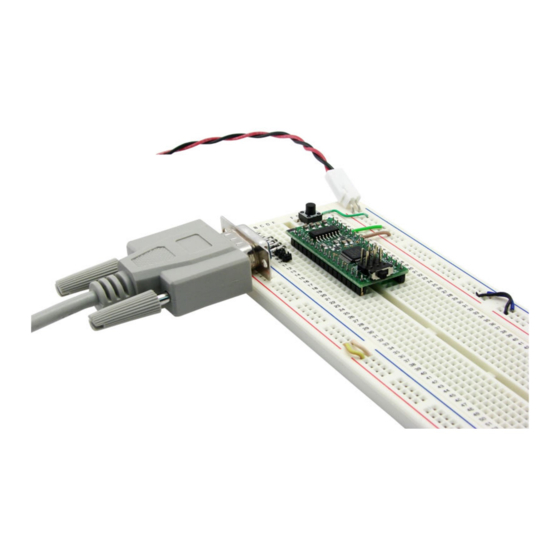
1.1 Hardware Setup:
Plug the NanoCore12DXC32 module into your solder-
less breadboard. Attach the supplied serial cable (may
vary from cable shown in photo) between the TX, RX,
and GROUND pins of the module (pins 1, 2, and 4,
respectively) and the PC's Com Port (i.e. serial port).
(see Fig. 1). If your PC does not have a Com Port,
you'll also need a USB-to-Comport adapter
(#USB2COM or #USB232).
You'll need a DC power supply of at least 6V and not exceeding about 9V. With the power off, attach or splice your
power supply onto the red and black power cable assembly that came with your kit. Red is positive and black is nega-
tive. This cable assembly was designed to plug conveniently into
your solderless breadboard next to the Vin and Ground pins on
NanoCore12DXC32. The Vin (+) pin (32) goes to the red wire,
and VSS/Ground (-) pin (31) goes to the black wire. Refer to
Figure 1
is shipped from the factory with a demo program loaded into
Figure 3
Figure 4
module to logic low (i.e. temporarily connect it to GROUND). If that doesn't work,
re-read the above and verify your power supply voltage and connections.
Now press the Enter key on your PC keyboard, and NanoCore12 will re-send
the Demo Program Command Menu to your terminal window. If you got this far, it means that your module is suc-
cessfully powered up and running, and communication is work-
ing in both directions (i.e. transmit and receive).
1.3 Using the Demo Program:
Now it's a good idea to attach a couple of LEDs to see the re-
sults of some of the Demo Program commands. Refer to Figure
8 for the connection details. The current-limiting resistor value
should be no less than 680 Ohms, to avoid drawing too much
current from the pin.
•Type the digit 0 repeatedly and observe that the LED con-
nected to PT0 (pin 19) toggles on and off.
•Type the digit 1 repeatedly and observe that the LED con-
nected to PT1 (pin 20) toggles on and off.
Figure 2 for connection details.
Note: if you have a regulated
power supply of 3V or 5V, you
can connect it directly between
Vcc (pin 29, positive) and Vss
(pin 31, negative), and leave
Vin unconnected.
apply power yet!
1.2 Verifying your Setup.
At this point, you should
have your hardware all set up
and ready to test.
Each NanoCore12 module
Flash. To use the demo program, you will need to launch a
terminal program on your PC. Some examples of terminal pro-
grams you can use are: HyperTerminal (included with Win-
dows), TeraTerm, MiniIDE, and the terminal program inside
ImageCraft's C compiler (ICC12 or ICC for CPU12). In this
guide, we will use TeraTermPro, available on the Resources
page of www.NanoCore12.com, or here:
http://support.technologicalarts.ca/docs/Third%20Party/TeraTe
rmPro/Tera%20Term%20Pro%202.3.zip
After unZIPping and installing TeraTermPro, launch the pro-
gram and select Setup from the drop-down menu. Select Ter-
minal (see Figure 3) and click on the button next to Term size
= win size, then click OK (see Figure 4). Again from Setup,
select Serial Port (see Figure 5) and select
the com Port you are using, 9600 for Baud rate, Data: 8 bit, Parity:
none, Stop: 1 bit, Flow control:
none (see Figure 6). Now, make sure
the Load/Run switch on
NanoCore12DXC32 is in the RUN posi-
tion and apply power to the module, as
described in 1.1, above. You should
immediately see a menu displayed in
your terminal window (see Figure 7). If
you don't see the menu, momentarily
bring the RESET pin (pin 30) on the
TX (RS232)
RX (RS232)
DTR (N/C)
VSS
AN0/PAD00
AN1/PAD01
AN2/PAD02
AN3/PAD03
AN4/PAD04
Do not
AN5/PAD05 10
AN6/PAD06 11
AN7/PAD07 12
PM5/SCK 13
PM4/MOSI 14
PM3/SS* 15
PM2/MISO 16
1
32 VIN
2
31 VSS (GROUND)
3
30 RESET*
4
29 VCC
5
28 PE0/XIRQ*
6
27 PE1/IRQ*
7
26 PT7/IOC7
8
25 PT6/IOC6
9
24 PT5/IOC5
23 PT4/IOC4/PW4
22 PT3/IOC3/PW3
21 PT2/IOC2/PW2
BDM IN
20 PT1/IOC1/PW1
19 PT0/IOC0/PW0
18 PM0/RXCAN
17 PM1/TXCAN
Figure 2
Figure 5
Figure 6
Figure 7
Advertisement
Table of Contents

Summary of Contents for TECHNOLOGICAL ARTISANS NanoCore12DXC32
- Page 1 TX (RS232) 32 VIN your solderless breadboard next to the Vin and Ground pins on NanoCore12DXC32. The Vin (+) pin (32) goes to the red wire, RX (RS232) 31 VSS (GROUND) and VSS/Ground (-) pin (31) goes to the black wire. Refer to...
- Page 2 1.45 Going Further. For troubleshooting help, or to start writing your own programs for NanoCore12DXC32, visit the Documentation page of www.NanoCore12.com. Not only does it cover all hardware details of the NanoCore12 family and accessories, but it contains thorough Figure 12 tutorials and numerous examples for using Assembler, BASIC, and C.
Need help?
Do you have a question about the NanoCore12DXC32 and is the answer not in the manual?
Questions and answers